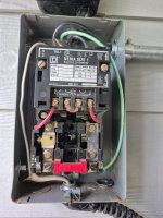
This motor controller is wired to my old upright air compressor. It's been running fine for years but curiosity got the better of me and I'm simply trying to piece together how it all works. I got this compressor years ago from my father in law. I have always questioned the basic light switch that he had wired into the system. It's running off of 240V single phase.
Looking at my pic it seems like the red wire is getting 120v from being connected at the same lug as one of the hot wires from the fuse box. That red wire goes up to the light switch. When the switch is turned on it sends power down the black wire to the pressure switch on the tank. Not sure what the white wires job is after that but the circuit basically turns the compressor on or off. In the photo the motor is currently not wired in because I'm replacing it with a new one.
Any ideas? To me it seems like the switch is handling a standard single-phase 120V leg so it's safe to keep it?