To avoid these ads, REGISTER NOW!

Craftsman 3/4 hp Block Grinder not reaching speed

drs3317

Well-known member
Joined
Jan 31, 2016
Messages
126
Location
Western Maryland
I recently bought an older (1974) Craftsman block grinder. Model 397.19450 When switched on it would not turn unless given a turn by hand. Also I checked the speed with my tachometer and found it was only spinning 1790 rpm. This is half of the rated speed of 3580 rpm. I suspected the capacitor for the starting issue and replaced it. It made no difference and of course still only spinning 1790 rpm. I check the wiring to make sure it had not been converted to 230 volts and found it is still wired at 115 volts. I'm not to educated on motors and have no idea what to check next. Hopeful for any ideas or suggestions.
Thanks
 

Attachments

  • 70430049665__0798C0F3-29BA-4D15-A79F-616BB6ADA05F.jpg
    70430049665__0798C0F3-29BA-4D15-A79F-616BB6ADA05F.jpg
    82.6 KB · Views: 66
  • 70430051197__C6EF07FA-6086-4ADE-A0C8-D012F1837DDA.jpg
    70430051197__C6EF07FA-6086-4ADE-A0C8-D012F1837DDA.jpg
    132 KB · Views: 58
  • 70430052988__9429300F-440D-4485-AD94-DF2B1673C2D6.jpg
    70430052988__9429300F-440D-4485-AD94-DF2B1673C2D6.jpg
    91.9 KB · Views: 49
To avoid these ads, REGISTER NOW!
OP
D

drs3317

Well-known member
Joined
Jan 31, 2016
Messages
126
Location
Western Maryland
could be the centrifugal switch not switching the capacitor into the start winding since you have to spin it by hand and cap replacement didnt fix it. are you sure the cap was bad?
I'm not a motor guy or even a sparky so I did not know how to test the cap so for $8. I just replaced it. And since it changed nothing I can only assume the older one was not bad.
As for the centrifugal switch, this motor has none. It uses a starting relay. If you look at the wiring diagram I attached above you can see it. I had thought it was just a junction block until some further research and now wondering if it could be the problem. But how to test it or find a replacement is the next question. Thanks
 

wyliesdiesels

Well-known member
Joined
Aug 14, 2012
Messages
20,066
Location
Modesto, CA
I'm not a motor guy or even a sparky so I did not know how to test the cap so for $8. I just replaced it. And since it changed nothing I can only assume the older one was not bad.
As for the centrifugal switch, this motor has none. It uses a starting relay. If you look at the wiring diagram I attached above you can see it. I had thought it was just a junction block until some further research and now wondering if it could be the problem. But how to test it or find a replacement is the next question. Thanks
aww ok i didnt look at the diagram too close. if you have a multimeter it wouldnt be hard to test the relay...
 

torqueman2002

Well-known member
Joined
Jun 3, 2009
Messages
6,142
Location
SE Michigan
I will respond/comment here, rather than the other thread you also posted in (Craftsman Block motor Bench Grinders - What's the Fuss (with resource information)).

The main concern on a replacement capacitor is the 'mfd' rating. It should be within +10% of the OEM, and same voltage range.

The relays are very robust, rarely fail. That said, I would double check the connections to it are correct (from the picture, it isn't clear what wire colors are connected on #2 & 3. See attached diagram, for reference. Also, verify all terminals are tight and clean.

As far as testing the relay, it is a current-style relay, not like the voltage-style relays that are very common on vehicles, .... Therefore I don't know how to easily check it's operation because it's a function of the current (amps) produced in the start-up coil, as the motor is nearing full speed.

It's is curious that the speed it runs at is '1790 rpm. This is half of the rated speed of 3580 rpm.' That is what I'd think a motor wired for 230V, would run when it is connected to 115V.

397_19440 P1120906.JPG
 
OP
D

drs3317

Well-known member
Joined
Jan 31, 2016
Messages
126
Location
Western Maryland
Thanks guys. @torqueman2002 I will follow your instructions and report back what I find. I was planning to clean all the connections next.

It's is curious that the speed it runs at is '1790 rpm. This is half of the rated speed of 3580 rpm.' That is what I'd think a motor wired for 230V, would run when it is connected to 115V.
That is exactly what I was thinking and why I checked the wires against the diagram. However, I am following your advise and checking again paying special attention to #2 & #3.

I will add the seller said it was running fine until I arrived and he moved it from his basement to the front porch. He admitted he thought it was the cap also and was going to attempt the repair himself. He then lowered the price that I was sure the parts were worth much more if I parted it out. Additionally, the grinder appeared to have never been taken apart.

Thanks again!
 

torqueman2002

Well-known member
Joined
Jun 3, 2009
Messages
6,142
Location
SE Michigan
I looked through copies of Craftsman grinder owner manuals and found a 3/4-HP, dual-voltage model that is probably very similar to your model.

If you'd like a free PDF copy of it (model: 397.19470), it is on VintageMachinery's website. Link below.
http://vintagemachinery.org/mfgindex/detail.aspx?id=222&tab=3&sort=4&th=false&fl=Grinder

You didn't mention if the grinder tries to spin. Sometimes one will get 'hung up' and need a spin by hand to get it moving. Usually there is a humming (60Hz) sound too. Like when a fan is on but the blade can't turn.

If this is happening, the start-up circuit can get overloaded (around 3-5 seconds) and the thin wires will over heat, smoke, and burn open.

You may want to see if the rotor shaft spins easily and freely, maybe even taking off the grinding wheels (the LH one has a left-hand thread).

Good luck. Let us know how it is going.
 
OP
D

drs3317

Well-known member
Joined
Jan 31, 2016
Messages
126
Location
Western Maryland
Thanks for the link to the manual. Very close to mine being dated 1974 also. However, mine has the auxiliary base with the cast tool rests.

You didn't mention if the grinder tries to spin. Sometimes one will get 'hung up' and need a spin by hand to get it moving. Usually there is a humming (60Hz) sound too. Like when a fan is on but the blade can't turn.
The shaft turns smooth and freely when not turned on. Once switched on it hums but does not spin on its own. With a short turn by hand it runs up but only to half speed.
 

torqueman2002

Well-known member
Joined
Jun 3, 2009
Messages
6,142
Location
SE Michigan
I sure hope it does not turn out to be that.

Tomorrow I'll check the resistance values on a similar model and post them, so you can check their condition.

Another way is to look at the start-up winding, which are the thin wires. In your picture above, the main/run windings are visible. They are a bright copper color and less numerous than the thinner start-up winding wires, which are not visible. They should also be about as bright copper.

If they are noticeably darker, it is possible they have been damaged by over current.

Here is an example of an over-current damaged 1/2-HP Block grinder winding. The damaged, open-circuit, start-up winding is closest to the rotor area and can't always be easily detected by visual inspection. It is very dark and charred looking in comparison to main windings, which are heavier gauge.

The pictures of a Block grinder I tore down, hoping to repair the open in the winding. It did not turn out well. I did find the break, but I could not solder it back together. I found it impossible to get the wire clean enough to get the solder to stick. The charring and the varnish insulation bested my efforts.
 

Attachments

  • P1110033.JPG
    P1110033.JPG
    809.2 KB · Views: 44
  • P1110034.JPG
    P1110034.JPG
    803.9 KB · Views: 41
Last edited:

torqueman2002

Well-known member
Joined
Jun 3, 2009
Messages
6,142
Location
SE Michigan
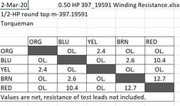
Here are resistance measurements from a 1/2-HP, dual voltage Block grinder. The values will be different from the 3/4-HP model, but they should serve as a reference at least.

Of course, the terminals need to be disconnected from the switch, relay, capacitor, ....

Oh, don't forget to unplug the power cord. o_O LOL

0.50 HP 397_19591 Winding Resistance.JPG
 
Last edited:
OP
D

drs3317

Well-known member
Joined
Jan 31, 2016
Messages
126
Location
Western Maryland
This morning I took apart all the wiring connections and cleaned them and nothing has changed.
I took a photo of the windings,(below). It appears the small wires are still shinny. However, the large wire,(outside) seem to be darker on one side with a black dust which can be wiped off.

The best I can tell there are four wires coming from the winding bundle. Blue, Red, Yellow, and Brown. The chart shows five so I will recheck again. The only orange is a jumper so not sure if that is what should be checked and on which end since its only a jumper?

The following are the readings I got;
Blue & Red....10.9
Blue & Brown...3.2
Brown & Red...13.9
Yellow & Brown...6.6

I have no idea what they should be or what these numbers mean. They do seem similar to the chart above except the brown & Yellow which does not show on the chart.

BTW, again, when the switch is turned on, the shaft jumps and wants to turn but the motor just hums until I give it a helping hand spin. I also noticed when giving the hand start it will run in either direction if that means anything?
 

Attachments

  • IMG_2045.jpg
    IMG_2045.jpg
    100.8 KB · Views: 28
  • IMG_2044.jpg
    IMG_2044.jpg
    73.4 KB · Views: 32

torqueman2002

Well-known member
Joined
Jun 3, 2009
Messages
6,142
Location
SE Michigan
drs - Good morning.

Good information, I am cautiously optimistic, to coin a phrase. The start-up winding Ohms out good, and appears normal.

The fact it will run in either direction is curious. It may be related to it not starting on it's own. The capacitor is part of the start-up circuit and it's function is to provide a phase shift. IIRC This provides a 'nudge' to the rotor to turn in the desired direction.

I'm a little out of my depth here. You may want to join and post in the OWWM website's Everything Electrical section. BTW - OWWM is the 'sister' website to Vintage Machinery's website.
https://owwm.org/index.php?sid=8f7d7be6ca1829287b04a5c06d54114b

I'll need to digest your measurements and check my dual 3/4 HP and get back.

Meanwhile, I've labeled the wire colors in your original picture. I've found the wire colors tend to age over the years, so maybe this will help.

In this image:
Orange; 2 separate (1 from switch to windings, 1 jumper on relay term 1 -> 2)
Brown; 1
Yellow; 1
Red; 2 separate (1 from start-up winding to cap, 1 from cap to relay term 2)
Blue; 1
CM 0_75 M-397_19450 wiring.jpg
 
Last edited:

torqueman2002

Well-known member
Joined
Jun 3, 2009
Messages
6,142
Location
SE Michigan
drs - Good afternoon.

I pulled out my 3/4-HP m-397.19450, dual voltage Block and measured the resistance values of the windings. I need to do some thinking about how your Block compares to these, once you get a chance to re-check.


0.75 HP 397_19450 Winding Resistance.JPG
 
OP
D

drs3317

Well-known member
Joined
Jan 31, 2016
Messages
126
Location
Western Maryland
torqueman, again thank you for taking the time to assist me. Without your guidance I would be lost. Labeling the wire colors was a big help. I think I had some wrong before. Now that you located the orange for me it was much more clear. I now have six readings which I believe to be the correct ones as follows;

Orange-Yellow....3.4

Blue-Brown........3.5
Blue-Red.............10.9

Yellow-Orange..3.2

Brown-Red.......13.3

Red-Blue......10.9

I tapped on the starter relay with a screwdriver handle and then another start test and I noticed the shaft jumped a very short in the correct direction so that part is good. I tapped on the relay again while it was on just a few seconds with no further results.
 
To avoid these ads, REGISTER NOW!
OP
D

drs3317

Well-known member
Joined
Jan 31, 2016
Messages
126
Location
Western Maryland
Have you ever taken the stater relay apart? Was thinking of giving it a "look see" but don't want springs and things flying across my shop.
 

FrankLee

Well-known member
Joined
Sep 13, 2010
Messages
3,617
Location
seMI, 48317
Have you ever taken the stater relay apart? Was thinking of giving it a "look see" but don't want springs and things flying across my shop.
Check this post and the following conversation.
Not sure if it's the exact same part, but should give you the gist.
 

torqueman2002

Well-known member
Joined
Jun 3, 2009
Messages
6,142
Location
SE Michigan
drs - More good info. We're closing in on what is going on.

I just need some more readings. I put your measurements in a table below. As you can see, some readings of the same wire are very similar, ie: Orange-Yellow....3.4 & Yellow-Orange..3.2. Not very significant, but just to be thorough, would you mind measuring the ones shown as 'ina'?

Let me look for a picture of this style relay's internals.

0.75 HP 397_19450 Winding Resistance b.JPG
 
Last edited:

torqueman2002

Well-known member
Joined
Jun 3, 2009
Messages
6,142
Location
SE Michigan
I found the exact relay (B4N 4CR-21-713) from my 3/4-HP m-397.19450, that I opened up to see what was inside! I have noted the resistance value of the pull-in coil (no power applied).

Terminals:
1 - neutral (White wire) & jumper to relay terminal 4 (Orange wire) & optional Lamp
2 - capacitor (Red wire)
3 - main winding 1 (Yellow wire)
4 - main winding 2 (Brown wire) & jumper to relay terminal 1 (Orange wire)
P1110204 B4N 4CR-21-713 a.JPG

This is the bottom view with the cover removed. To remove the cover it's a simple matter of removing the screw.
With no power/current applied, the contacts are normally open, thereby no power goes through the start-up circuit/winding.
P1110211 B4N 4CR-21-713 a.JPG

This view shows terminal 2 removed, and the moving portion of the relay, it's action is like a 'teeter-totter', when the coil is energized it pulls the right hand side of the lever down, resulting in the left hand side connecting terminal 2 and 4. (note the pads used to transfer the current from terminal 2 to 4 and some charring from arching) Also, note the brass like pin in the middle of the relay. The is also a spring that hooks over the 'teeter-totter' about 1/3 way from the left of the contact bar. This spring assists the 'teeter-totter' to open the contact between terminals 2 and 4, when the relay is de-energized.
P1110215 B4N 4CR-21-713 a.JPG

This is a side view of the 'teeter-totter' and terminal 2. Note the small spring, I think this is to assist the 'teeter-totter' closing the contacts, when the relay is energized.
P1110217 B4N 4CR-21-713 a.JPG
 

torqueman2002

Well-known member
Joined
Jun 3, 2009
Messages
6,142
Location
SE Michigan
I found additional information on the relay. PM me please.

Meanwhile, there is info on Klixon relays on this site. https://www.sensata.com/


I found this, it should help with your measurements. I'm not sure what HP this is for, or if it is critical. The values seem close.
Sears-Grinder-Mod.jpg
 

marinusdees

Well-known member
Joined
Oct 30, 2012
Messages
1,325
Location
Edgewood, Washington
I recently bought an older (1974) Craftsman block grinder. Model 397.19450 When switched on it would not turn unless given a turn by hand. Also I checked the speed with my tachometer and found it was only spinning 1790 rpm. This is half of the rated speed of 3580 rpm. I suspected the capacitor for the starting issue and replaced it. It made no difference and of course still only spinning 1790 rpm. I check the wiring to make sure it had not been converted to 230 volts and found it is still wired at 115 volts. I'm not to educated on motors and have no idea what to check next. Hopeful for any ideas or suggestions.
Thanks
After all this, it seems to me the fact that it will start either direction if manually spun indicates the start winding is not in the circuit. Ergo, the start relay is faulty, not connecting the start winding. The relay is magnetically operated to remove the start winding from the circuit a fraction of a second after the motor starts spinning. No start winding to produce a rotating magnetic field, no start. If the start winding ohms OK, it's the relay. If the start winding ohms open, it's the winding. The relay is another way to disconnect the start winding from the circuit. And, they can and do fail. My motor repair shop buddy tell me they are still available. Didn't ask him where.
 
OP
D

drs3317

Well-known member
Joined
Jan 31, 2016
Messages
126
Location
Western Maryland
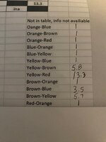
TM, I took the additional readings you requested.
IMG_2054.jpg

Also after taking the readings I removed the starter relay and disassembled it. The contacts look a little dirty but not too bad. The springs look good. I cleaned the contacts and assembled. Then I read we are on the same page, and tomorrow I will take readings and compare to your post. The farther I go the more baffled I become. So far everything seems to check out? A few more readings on the relay and then nothing left. Keep thinking!
 

Attachments

  • IMG_2052.jpg
    IMG_2052.jpg
    63.9 KB · Views: 29
  • IMG_2053.jpg
    IMG_2053.jpg
    77.3 KB · Views: 41

mm08822

Well-known member
Joined
Jan 13, 2012
Messages
6,029
Location
NJ
Here is a link to the cut sheet from Sensata and it explains the drop in/drop out current values for each part #.


One site I saw selling these parts was ~$63.00

Edit:
The relay switching contacts look very pitted. May be ok after cleaning but probably not for too long. Manually move the relay armature so the switching contacts close and read the resistance between 2 - 4.

You could also try and read if there is a significant voltage drop across 2-4 when starting up motor and these contacts are closed (relay energized).
 
Last edited:

torqueman2002

Well-known member
Joined
Jun 3, 2009
Messages
6,142
Location
SE Michigan
... The relay switching contacts look very pitted. May be ok after cleaning but probably not for too long. Manually move the relay armature so the switching contacts close and read the resistance between 2 - 4. ....
The relay in OP's post #24 shows the contacts from the bottom of the terminals 2 & 4; actual contact pads are not visible.

However, in post #21 they are visible, but that is not OP's relay, same model though.

You are spot on, the contacts in #21 do need burnishing.

In fact, I have been thinking of the symptoms:
1) hums on start
2) does not spin on start
3) does spin if helped with a hand-spin, will spin in either direction
These can be caused by a start-up circuit that is not energized
4) spins at 1/2 speed, if hand started

1 through 4 could be caused if the start-up winding and the main 2 winding are not powered up; or if relay terminal 2 is not making contact with terminal 4 - neutral path via. orange jumper to terminal 1.

I hope cleaning the internal contacts (relay contact burnisher files or similar, and Deoxit d5 spray contact cleaner/kit -- both on Amazon), and verifying all the grinder's terminal for fit, cleanliness, and routing, will fix the problem.

If it turns out the relay is faulty, I may have a used relay from a similar 3/4-HP block.
 
Last edited:
OP
D

drs3317

Well-known member
Joined
Jan 31, 2016
Messages
126
Location
Western Maryland
I haven’t given in on this yet and plan to follow through tomorrow with cleaning contacts rechecking all wires. Then testing and taking readings on the relay. I’d forgotten we had plans Sunday today and will not be home until late. tm, I received your pm and will respond later when I get home. I feel we are closing in. With your instructions I’m sure we can figure out if i follow your directions. Thanks.
 

mm08822

Well-known member
Joined
Jan 13, 2012
Messages
6,029
Location
NJ
The relay in OP's post #24 shows the contacts from the bottom of the terminals 2 & 4; actual contact pads are not visible.

However, in post #21 they are visible, but that is not OP's relay, same model though.


You are spot on, the contacts in #21 do need burnishing.

In fact, I have been thinking of the symptoms:
1) hums on start
2) does not spin on start
3) does spin if helped with a hand-spin, will spin in either direction
These can be caused by a start-up circuit that is not energized
4) spins at 1/2 speed, if hand started

1 through 4 could be caused if the start-up winding and the main 2 winding are not powered up; or if relay terminal 2 is not making contact with terminal 4 - neutral path via. orange jumper to terminal 1.

I hope cleaning the internal contacts (relay contact burnisher files or similar, and Deoxit d5 spray contact cleaner/kit -- both on Amazon), and verifying all the grinder's terminal for fit, cleanliness, and routing, will fix the problem.

If it turns out the relay is faulty, I may have a used relay from a similar 3/4-HP block.
Understood. I assumed the same condition for the OP's relay as your pics were from the same application.
 
OP
D

drs3317

Well-known member
Joined
Jan 31, 2016
Messages
126
Location
Western Maryland
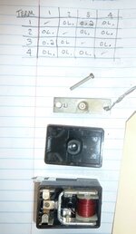
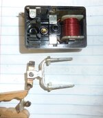
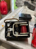
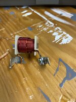
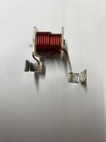
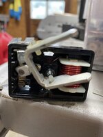
@torqueman2002 , I'll send a PM shortly. Thank you, Thank you, Thank you. Your instructions and thoughts were spot on. I cleaned all the contacts first then checked the relay AFTER all connections were disconnected. Both readings across 1 & 3 and 2 & 4 were the same, showed a "1" on my meter. Nothing,..open circuit. I took the relay apart and this time disassembled it and found a lead from the coil was broken at the terminal. I cleaned the broken wire and terminal and used a piece of a small wire along side them and soldered the together. Put it all back together and she fired right up spinning high speed! Great learning experience. Thanks again.
 

Attachments

  • 13E4F49E-6E4C-4CEB-BA6F-EF994870DB80.jpeg
    13E4F49E-6E4C-4CEB-BA6F-EF994870DB80.jpeg
    697.5 KB · Views: 31
  • 5917992A-D5E8-46E1-BDF5-EEE9B098E5C8.jpeg
    5917992A-D5E8-46E1-BDF5-EEE9B098E5C8.jpeg
    436.7 KB · Views: 30
  • E3137F8F-CCA6-4CD3-AF74-4FF4A9863465.jpeg
    E3137F8F-CCA6-4CD3-AF74-4FF4A9863465.jpeg
    363.7 KB · Views: 29
  • 7BA60D73-C96B-4352-B718-DA6C66BD7B19.jpeg
    7BA60D73-C96B-4352-B718-DA6C66BD7B19.jpeg
    577 KB · Views: 36

torqueman2002

Well-known member
Joined
Jun 3, 2009
Messages
6,142
Location
SE Michigan
Congratulations! :beer:

I'll be a blue nosed gopher! Never would've thought of that.

I just took a brake from checking my 3/4-HP, and some other single voltage 3/4-HP models. Interesting, the single voltage 3/4 models do not use a capacitor, and the relay has only 3 terminals. Surprised me.

I am going to re-check my 3/4 m-397.19450. When I powered it up, to measure the voltage-drop on terms 2 & 4, I would only turn at 1/2 speed! :headscrat

It didn't hum and did start, but never reached full speed. Here we go again. LOL
 
OP
D

drs3317

Well-known member
Joined
Jan 31, 2016
Messages
126
Location
Western Maryland
Congratulations! :beer:

I'll be a blue nosed gopher! Never would've thought of that.

I just took a brake from checking my 3/4-HP, and some other single voltage 3/4-HP models. Interesting, the single voltage 3/4 models do not use a capacitor, and the relay has only 3 terminals. Surprised me.

I am going to re-check my 3/4 m-397.19450. When I powered it up, to measure the voltage-drop on terms 2 & 4, I would only turn at 1/2 speed! :headscrat

It didn't hum and did start, but never reached full speed. Here we go again. LOL
Since I am not a professional in electric matters I am always amazed at how the electrical engineers design develop different circuits. Even the simple motor that can be wired 115v or 230v is amazing to me. The most I can do is simple testing when I have good instructions and search for broken or burnt things. In this case a simple broken wire was located and was able to be repaired. No idea why or how it broke. Maybe just time and vibration. Had I not located the brake or been able to repair it, my next step may have been locating another starter relay. Anyway, I had a smile for quite a while after it was running. Thanks again tm
 

marinusdees

Well-known member
Joined
Oct 30, 2012
Messages
1,325
Location
Edgewood, Washington
Since I am not a professional in electric matters I am always amazed at how the electrical engineers design develop different circuits. Even the simple motor that can be wired 115v or 230v is amazing to me. The most I can do is simple testing when I have good instructions and search for broken or burnt things. In this case a simple broken wire was located and was able to be repaired. No idea why or how it broke. Maybe just time and vibration. Had I not located the brake or been able to repair it, my next step may have been locating another starter relay. Anyway, I had a smile for quite a while after it was running. Thanks again tm
Dual voltage motors have two (sets, sometimes) of run windings. For 120 configuration, the windings are run in parallel. For 240v configuration, they are run in series. If you can draw this out, you'll see how and why.
 
Last edited:
To avoid these ads, REGISTER NOW!
Top Bottom