
You are using an out of date browser. It may not display this or other websites correctly.
You should upgrade or use an alternative browser.
You should upgrade or use an alternative browser.
Modified wiring, your thoughts?
- Thread starter paulmars
- Start date
wyliesdiesels
Well-known member
im not understanding what you want to do.
walta
Well-known member
The only reason to want to move the wire is because you think the amount of power the meter is consuming is significant. I own a few meters that look similar and I doubt they are sensitive enough to detect themselves.
It looks like the meter is capable of 100 amps and the meter might draw 0.01 amps it is undetectable with the sensor being used.
Walta
It looks like the meter is capable of 100 amps and the meter might draw 0.01 amps it is undetectable with the sensor being used.
Walta
acer66
Well-known member
Phantom posting.Why did above post before i posted it?
rlitman
Well-known member
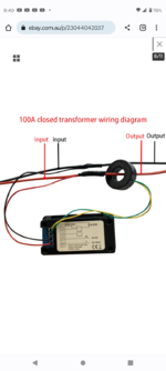
It will work just fine in either position. The amount of current drawn by the meter is significantly smaller than the accuracy of that CT, so it is way too small to be detected. However, it IS necessary for the meter to be connected to the same wire (somewhere) as the load, as it needs to know the voltage to tract the wattage, if you're using it for sub-metering energy. If you're just tracking current, any voltage source within the range of the meter will do.
The most important thing to be aware of if that if there is a load on the red wire going through the CT, then the CT MUST be connected to the meter or be shorted. Disconnecting the yellow or green wires while a load is passing through the CT will "do bad very things". Also, CTs like these are directional. Usually there's an arrow or dot or circle indicating the load side, and the meter will indicate which wires go where. I find it kind of odd that your example does not, but I suppose they could just be integrating absolute values.
The most important thing to be aware of if that if there is a load on the red wire going through the CT, then the CT MUST be connected to the meter or be shorted. Disconnecting the yellow or green wires while a load is passing through the CT will "do bad very things". Also, CTs like these are directional. Usually there's an arrow or dot or circle indicating the load side, and the meter will indicate which wires go where. I find it kind of odd that your example does not, but I suppose they could just be integrating absolute values.
alfredeneuman
Well-known member
^^^^^^THIS times 1,000^^^^^^the CT MUST be connected to the meter or be shorted.
If you disconnect it with a load going through, it will cause a extreme overvoltage condition, and damage the coil.
Last edited:
wyliesdiesels
Well-known member
since i have no experience with CTs, im curious. what are the "very bad things" that can happen?It will work just fine in either position. The amount of current drawn by the meter is significantly smaller than the accuracy of that CT, so it is way too small to be detected. However, it IS necessary for the meter to be connected to the same wire (somewhere) as the load, as it needs to know the voltage to tract the wattage, if you're using it for sub-metering energy. If you're just tracking current, any voltage source within the range of the meter will do.
The most important thing to be aware of if that if there is a load on the red wire going through the CT, then the CT MUST be connected to the meter or be shorted. Disconnecting the yellow or green wires while a load is passing through the CT will "do very bad things". Also, CTs like these are directional. Usually there's an arrow or dot or circle indicating the load side, and the meter will indicate which wires go where. I find it kind of odd that your example does not, but I suppose they could just be integrating absolute values.
BTW i fixed the text for you
rlitman
Well-known member
A CT will try to have current flowing through the secondary leads that's proportional to the current passing through the loop. When shorted, that's no big deal, because the voltage is 0. When the circuit is open, the voltage will rise until something fails. The usual result is insulation inside of the loop being overcome and internal arcing (destroying the CT at a minimum), but it could easily be more dramatic as well with sparks, flame and then some.since i have no experience with CTs, im curious. what are the "very bad things" that can happen?
BTW i fixed the text for you
CT's used in higher end switch gear either have shorting provisions as part of the CT itself or somewhere in the output circuit may contain provisions to accomplish the same, such as terminal blocks which accept a jumper.since i have no experience with CTs, im curious. what are the "very bad things" that can happen?
A single ct meter in switchgear is common where a rotary selector switch is used to pick which phase to read. The rotary switch also provides the necessary shorting across two of the three ct's at a time.

dcg9381
Well-known member
I'm looking for "dumb" kWh meter that's reset-able. What's the model of this? Happy with it?