To avoid these ads, REGISTER NOW!

Wiring a magnetic starter on a 7.5 single phase Champion compressor

JamesHenry

Member
Joined
Oct 6, 2023
Messages
7
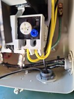
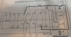
Hey guys, I'm trying to wire my 7.5 Champion compressor. Got it from someone and the mag starter was missing. I bought a 48 volt starter and don't understand the wiring diagram. I have looked through some of the old posts but I am still unclear on how to wire it. I will post pics in hopes someone can help. I had the black power wire on L1 and the *********** wire to L3. I put the ps motor wire to A1 and the line wire from ps on L1. I put the oil safety switch on L3 and the other oil wire on T1. I put the motor wires on T1 and T3. I flipped the breaker and it kicked right back off. I have 240v for power and it's a 50 amp breaker on the wall. The motor is a Baldor 7.5, Any help will be appreciated. I went ahead and unhooked what I had until I get some help. Thanks guys!
 

Attachments

  • 20231009_152336.jpg
    20231009_152336.jpg
    588.1 KB · Views: 74
  • 20231009_152839.jpg
    20231009_152839.jpg
    466.5 KB · Views: 68
  • 20231009_152421.jpg
    20231009_152421.jpg
    493.2 KB · Views: 60
  • 20231009_152635.jpg
    20231009_152635.jpg
    933.9 KB · Views: 61
  • 20231009_152446.jpg
    20231009_152446.jpg
    658.9 KB · Views: 59
  • 20231009_152557.jpg
    20231009_152557.jpg
    510.6 KB · Views: 64
To avoid these ads, REGISTER NOW!

wyliesdiesels

Well-known member
Joined
Aug 14, 2012
Messages
20,089
Location
Modesto, CA
a 48volt rated starter coil will NOT work on 240v supply without a control step down transformer.

you need a 240v rated starter.

also that motor is too large to be using a nema plug. it needs to be hardwired to a disconnect unless the breaker panel is within sight of and less than 50' away from the breaker panel
 

mm08822

Well-known member
Joined
Jan 13, 2012
Messages
6,065
Location
NJ
a 48volt rated starter coil will NOT work on 240v supply without a control step down transformer.

you need a 240v rated starter.

also that motor is too large to be using a nema plug. it needs to be hardwired to a disconnect unless the breaker panel is within sight of and less than 50' away from the breaker panel
Not sure why OP said 48v. Label on coil indicates 208-240v.
 

mm08822

Well-known member
Joined
Jan 13, 2012
Messages
6,065
Location
NJ
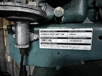
1) OP post a pic of the motor nameplate.
2) Is the oil switch for temp or level?
3) Is the oil switch normally open or closed , under what conditions?
4) Wire up 240v to line side of starter(1L1 and 5L3), connect grd lead to equipment frame. (CB off0.
5) Verify motor is straight 230v or motor leads configured for 230v input.
6) Connect motor power leads to starter (2T1, 6T3).
7) Push the black square actuator in to manually put the motor across the line.
8) Did motor start while actuator held in? Did cb trip? Run in the correct direction? Stay running and not trip shortly after start up?

These are the steps to prove out the power circuit. The control circuit is next after the above is functioning.
 
OP
J

JamesHenry

Member
Joined
Oct 6, 2023
Messages
7
a 48volt rated starter coil will NOT work on 240v supply without a control step down transformer.

you need a 240v rated starter.

also that motor is too large to be using a nema plug. it needs to be hardwired to a disconnect unless the breaker panel is within sight of and less than 50' away from the breaker panel
Hey wyliesdiesels: I meant 48 amps. The motor says 36-35. The panel is probably 15' away. I have been using a 5hp air compressor there for a few years but if I need to change up I will. I definitely am not a electrician as you can see. Lol! Thanks for the help
 
OP
J

JamesHenry

Member
Joined
Oct 6, 2023
Messages
7
1) OP post a pic of the motor nameplate.
2) Is the oil switch for temp or level?
3) Is the oil switch normally open or closed , under what conditions?
4) Wire up 240v to line side of starter(1L1 and 5L3), connect grd lead to equipment frame. (CB off0.
5) Verify motor is straight 230v or motor leads configured for 230v input.
6) Connect motor power leads to starter (2T1, 6T3).
7) Push the black square actuator in to manually put the motor across the line.
8) Did motor start while actuator held in? Did cb trip? Run in the correct direction? Stay running and not trip shortly after start up?

These are the steps to prove out the power circuit. The control circuit is next after the above is functioning.
Hey mm08822, thanks for the help! I will try hook it up like you said and try it. I will also post the nameplate for the motor! Thanks
 

Attachments

  • 20230923_183138.jpg
    20230923_183138.jpg
    621.3 KB · Views: 63

wyliesdiesels

Well-known member
Joined
Aug 14, 2012
Messages
20,089
Location
Modesto, CA
Hey wyliesdiesels: I meant 48 amps. The motor says 36-35. The panel is probably 15' away. I have been using a 5hp air compressor there for a few years but if I need to change up I will. I definitely am not a electrician as you can see. Lol! Thanks for the help
awww ok

the contactor needs to be rated for the same or higher HP as the motor. amps dont matter here

It will need to be hardwired. that nema plug is not rated for 7.5HP or even 5HP

you need 50a rated wire (40a FLC x 1.25). so either #8 THWN in conduit or #6/2 NM-b
 
OP
J

JamesHenry

Member
Joined
Oct 6, 2023
Messages
7
Thanks Wyliesdiesels! I will make sure I pickup the proper wiring tomorrow and try and get it powered properly then hook everything like mm08822 said to do. Thanks again!
 
OP
J

JamesHenry

Member
Joined
Oct 6, 2023
Messages
7
1) OP post a pic of the motor nameplate.
2) Is the oil switch for temp or level?
3) Is the oil switch normally open or closed , under what conditions?
4) Wire up 240v to line side of starter(1L1 and 5L3), connect grd lead to equipment frame. (CB off0.
5) Verify motor is straight 230v or motor leads configured for 230v input.
6) Connect motor power leads to starter (2T1, 6T3).
7) Push the black square actuator in to manually put the motor across the line.
8) Did motor start while actuator held in? Did cb trip? Run in the correct direction? Stay running and not trip shortly after start up?

These are the steps to prove out the power circuit. The control circuit is next after the above is functioning.
Hey mm08822, I got the compressor hardwired and hooked the wires as you said to do and pushed the black button and it ran with no issues and turned the right way. It did not cut off until I threw the breaker. 😅
Where do I hook up the pressure switch? I know there's 2 wires also for the low oil shutdown but I don't know how it works. Thanks for anymore help you can give!
 

mm08822

Well-known member
Joined
Jan 13, 2012
Messages
6,065
Location
NJ
Hey mm08822, I got the compressor hardwired and hooked the wires as you said to do and pushed the black button and it ran with no issues and turned the right way. It did not cut off until I threw the breaker. 😅
Where do I hook up the pressure switch? I know there's 2 wires also for the low oil shutdown but I don't know how it works. Thanks for anymore help you can give!
So I now figured out that the block with the clear plastic is the stop/start contacts and not some chichom overload block. The wiring has to be removed to those 2 buttons. The contact on the starter sealed around the open start button once the contactor was pushed in. That's why you had to open the CB.

  • Set the overload to 40A. (115% of FLAs).
  • Make sure to set the overload reset selector to "H". If the motor were to overload and trip the overload relay, you have to manually reset it. This is safer than an automatically resetting overload.
  • You need to answer question 2 & 3 to go further.
  • You will need a 2 position maintained selector switch to shut the compressor off when not needed. A 240v (277v) rated toggle switch will also work. The pressure switch is only to cycle the motor to build/maintain pressure. Without it, if your system gets a leak it would otherwise run indefinitely.
I'll work up a schematic once you answer 2/3.
 
To avoid these ads, REGISTER NOW!
OP
J

JamesHenry

Member
Joined
Oct 6, 2023
Messages
7
So I now figured out that the block with the clear plastic is the stop/start contacts and not some chichom overload block. The wiring has to be removed to those 2 buttons. The contact on the starter sealed around the open start button once the contactor was pushed in. That's why you had to open the CB.

  • Set the overload to 40A. (115% of FLAs).
  • Make sure to set the overload reset selector to "H". If the motor were to overload and trip the overload relay, you have to manually reset it. This is safer than an automatically resetting overload.
  • You need to answer question 2 & 3 to go further.
  • You will need a 2 position maintained selector switch to shut the compressor off when not needed. A 240v (277v) rated toggle switch will also work. The pressure switch is only to cycle the motor to build/maintain pressure. Without it, if your system gets a leak it would otherwise run indefinitely.
I'll work up a schematic once you answer 2/3.
Hey mm08822, I set the overload to 40A and the reset to H. On question 2 it's for oil level. On question 3 I'm not sure it is open or closed. I have never run the compressor before. I am not sure if I even need the low oil switch because it has a sight glass on it that's very easy to see. What are your thoughts?
 

mm08822

Well-known member
Joined
Jan 13, 2012
Messages
6,065
Location
NJ
I was sure it was a level switch but didn't want to assume. Probably open at low level. If it's a leaker, then you want it. Add it, if it gives nuisence faults and not leaking, then consider removing.
Here's what need for the control side:
1697072559410.png
Keep the wiring from 5L3 to 95, 96 to A1.
 
OP
J

JamesHenry

Member
Joined
Oct 6, 2023
Messages
7
I was sure it was a level switch but didn't want to assume. Probably open at low level. If it's a leaker, then you want it. Add it, if it gives nuisence faults and not leaking, then consider removing.
Here's what need for the control side:
1697072559410.png
Keep the wiring from 5L3 to 95, 96 to A1.
Thanks a lot for the drawing, It makes more sense to me. I'm going to try it when I get home from work today. I will report back and let you know how it worked out.
 

mrwilder

New member
Joined
Nov 25, 2017
Messages
3
Came across this thread while searching for the exact same question as OP as I have the same set-up. @mm08822 , is there no way to keep the off-on switch intact and use the 43/44 NO for the pressure switch? Not asking to argue, just trying to understand the limitation. What would the other NO/NC options be for on a contactor such as this?
 
Last edited:

mm08822

Well-known member
Joined
Jan 13, 2012
Messages
6,065
Location
NJ
Came across this thread while searching for the exact same question as OP as I have the same set-up. @mm08822 , is there no way to keep the off-on switch intact and use the 43/44 NO for the pressure switch? Not asking to argue, just trying to understand the limitation. What would the other NO/NC options be for on a contactor such as this?
No. 43/44 contact is a "slave" auxiliary contact. The pressure switch has to be placed in series with the contactor coil.

what do you mean by keep switch intact? It will have 2 wires connected to it no matter what.
 

mrwilder

New member
Joined
Nov 25, 2017
Messages
3
Intact as in used as an off-on switch.
In what practical application would the slave contract be used?
 

mrwilder

New member
Joined
Nov 25, 2017
Messages
3
Intact as in used as an off-on switch.
In what practical application would the slave contract be used?
Also, I have these wires routed to the motor power junction box. Would this be the oil sensor OP had?
 

Attachments

  • IMG_0068.jpeg
    IMG_0068.jpeg
    639.2 KB · Views: 22
  • IMG_0064.jpeg
    IMG_0064.jpeg
    945.6 KB · Views: 21

RPH

Well-known member
Joined
Dec 17, 2006
Messages
4,190
Location
Michigan Thumb
Intact as in used as an off-on switch.
In what practical application would the slave contract be used?
Auxiliary contacts are used to indicate contactor positions on/off. This could be used for an input to a PLC indicating that the contactor is on. Another use would be operation indicator lights or any other device that could use the information they produce.
 

mm08822

Well-known member
Joined
Jan 13, 2012
Messages
6,065
Location
NJ
The pic with the wires looks to be a level switch. Use a continuity test to measure if the circuit created by those wires is closed or open.

Drain the compressor oil and see if it changes state at some point during the draining. Replace the oil back in compressor. New oil would be a good idea now so you know when it was last changed.
 

nadogail

Well-known member
Joined
Jan 23, 2009
Messages
32,062
Location
Coronado, CA
Damn but It’s hard to discuss motor control wiring with someone who doesn’t speak Electrician.

I ran into a a similar situation when I bought a house in a village in Spain in 1965. I was not able to speak Spanish and the village plumber spoke no English. The Sears Roebuck catalog had good pictures of pipe fittings. With those pictures, a clean concrete floor and a piece of Chalk we found that we could both speak “Plumbing”. He got the running water plumbed into the house in one afternoon the next day.
 
To avoid these ads, REGISTER NOW!
Top Bottom