To avoid these ads, REGISTER NOW!

Old Winpower 10KW generator hookup?

R3 Fab

Member
Joined
Oct 31, 2023
Messages
16
I am trying to sort out hooking up my 3 ph. 10KW Winpower generator.
The original power distribution is missing.
Hoping someone here knows what I should be doing and can advise me.
It is 10KW and has a 30A breaker built in.
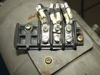
I see three lugs for power to a plug or panel.
I see a fourth on the generator housing that I "Think" is for the neutral and also a grounding rod?
I've been told a grounding rod is important for a generator to prevent the operating becoming the ground path when touching the generator, or even getting close to it.
I really want to have a single 208 3 ph. socket routed inside for my 2-post lift (Why I bought it), and three 120V 10A? (15A would be better.) single phase for backup power to home appliances.
Looking at an on-line chart this may have 104A at 208V 3ph.?
Going into the city on Wednesday so should be able to buy whatever is needed then.

No luck finding ANY documentation for this unit on-line.
 

Attachments

  • IMG_3546.jpeg
    IMG_3546.jpeg
    224.1 KB · Views: 78
  • IMG_3547.jpeg
    IMG_3547.jpeg
    236.1 KB · Views: 58
  • IMG_3548.jpeg
    IMG_3548.jpeg
    252.2 KB · Views: 55
  • IMG_3549.jpeg
    IMG_3549.jpeg
    242.1 KB · Views: 59
  • IMG_3550.jpeg
    IMG_3550.jpeg
    273.2 KB · Views: 63
To avoid these ads, REGISTER NOW!

wyliesdiesels

Well-known member
Joined
Aug 14, 2012
Messages
20,074
Location
Modesto, CA
I am trying to sort out hooking up my 3 ph. 10KW Winpower generator.
The original power distribution is missing.
Hoping someone here knows what I should be doing and can advise me.
It is 10KW and has a 30A breaker built in.
are you connecting this to a PoCo powered panel or a standalone panel?
I see three lugs for power to a plug or panel.
I see a fourth on the generator housing that I "Think" is for the neutral and also a grounding rod?
I've been told a grounding rod is important for a generator to prevent the operator becoming the ground path when touching the generator, or even getting close to it.
who told you this? its completely wrong. a grounding electrode has nothing to do with fault current or energized chassis. grounding electrodes are for grounding lightning, limiting voltage potential to earth, and shunting HV primary current when HV lines contact secondary lines.

an equipment grounding conductor on the other hand is to prevent current from energizing unintended pathways such as a generator chassis.
I really want to have a single 208 3 ph. socket routed inside for my 2-post lift (Why I bought it), and three 120V 10A? (15A would be better.) single phase for backup power to home appliances.
so youre distributing power via extension cords?
Looking at an on-line chart this may have 104A at 208V 3ph.?
Going into the city on Wednesday so should be able to buy whatever is needed then.

No luck finding ANY documentation for this unit on-line.
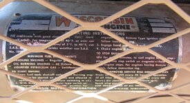
nope read the nameplate again.

it says 27.8a, which is the ampacity available.

10kW / 208v = 48.08a / 1.732 = 27.76a
 
OP
R

R3 Fab

Member
Joined
Oct 31, 2023
Messages
16
Stand alone panel, if I get to use one.
Lug on generator is the Ground/Neutral?
208 3ph cord to the Lift, I was hoping for covered outlets for single phase use.
Propane powered but still outside.
Power outages are too common here so was hoping to be able to run Mom's oxygen concentrator and maybe the refrigerator when the lift is not in use.
Ground rod still a good idea or not? Connect to the generator platform?

If I am understanding you correctly 110/120v will not be available, disappointing but simpler and cheaper.
28A is enough for the lift.
Seems I will need 10GA wire.

Sent an email with pics to Winpower but no response yet.
So far I have not been able to identify the actual model of the unit.
 
OP
R

R3 Fab

Member
Joined
Oct 31, 2023
Messages
16
208V divided by three legs = ?
Three "110V" legs to balance the load?
Pretty rusty on this, why I posted.

I rebuild Weber carbs, build cars from scratch, run CNC machines, but high voltage is not my strong suit.
 

mike93lx

ALLIANCE MEMBER
Joined
Dec 9, 2013
Messages
37,932
Location
Richmond, VA
The nameplate says 120/208. Neutral to hot will be 120v single phase.

It just seemed odd when you said "If I am understanding you correctly 110/120v will not be available". I didn't see that mentioned by another poster
 
OP
R

R3 Fab

Member
Joined
Oct 31, 2023
Messages
16
Okay, I have three connecting lugs at the left of the unit and one more on the end of the generator itself.
I believe the three at the left are the generator output "Legs" and the one at the end of the generator housing is the "Nuetral"?
That is four wires which I know to be needed for 3ph.
So where does Ground come into the picture?
"Neutral" is also Ground?
Trying to not get zapped, or fry any equipment.
No I cannot just call someone, "Fixed income" and not wealthy.
 

micromind

Well-known member
Joined
Sep 24, 2023
Messages
3,106
Location
Fernley, Nevada, about 30 miles east of Reno.
What Wylie posted above is exactly correct. The vast majority of online charts are pure garbage. They're written by people who have absolutely no idea what they're talking about.

Usually, a generator like this will have 3 output terminals plus one for the neutral/ground. usually the neutral and ground are connected together, as they should be.

Be very careful to keep the gen separate from the utility. If they are connected together, there'll be a fight and the gen will lose........
 
OP
R

R3 Fab

Member
Joined
Oct 31, 2023
Messages
16
Three terminal block at the left, single terminal on the generator itself.
Neutral/Ground is the terminal at the generator, correct?
This will never touch utility power.

Wired to a distribution box I should be able to divide the legs into three 110V 10A circuits and one 30A 208 3 ph.
I expect that I will not be able to run the 208 and 110 at the same time, not an issue, primary use is the 208 for my lift.
 

Attachments

  • IMG_3547.jpeg
    IMG_3547.jpeg
    236.1 KB · Views: 72

wyliesdiesels

Well-known member
Joined
Aug 14, 2012
Messages
20,074
Location
Modesto, CA
Stand alone panel, if I get to use one.
Lug on generator is the Ground/Neutral?

208 3ph cord to the Lift, I was hoping for covered outlets for single phase use.
Propane powered but still outside.
Power outages are too common here so was hoping to be able to run Mom's oxygen concentrator and maybe the refrigerator when the lift is not in use.
Ground rod still a good idea or not? Connect to the generator platform?

If I am understanding you correctly 110/120v will not be available, disappointing but simpler and cheaper.
28A is enough for the lift.
Seems I will need 10GA wire.


Sent an email with pics to Winpower but no response yet.
So far I have not been able to identify the actual model of the unit.
since this will be a stand alone aka separate derived source, the neutral and ground need to be bonded and yes you should put in 2 ground rods, connected to the neutral terminal. if this were to connect to a panel with a transfer switch, then the neutral would need to be isolated and ground rods would not be needed.

why would 120v NOT be available? it would be. please do some reading on 208Y/120v systems... you have ~27a available per leg. where is this chart that states you have 104a available? its completely wrong. the math just doesnt pencil out. even if it was single phase you would still only have 48a available per leg.

yes you need #10 wire.

since you havent told us the HP rating on the lift motor, I cant say whether this generator will be enough for it

post a pic of the motor nameplate on the lift
 

wyliesdiesels

Well-known member
Joined
Aug 14, 2012
Messages
20,074
Location
Modesto, CA
208V divided by three legs = ?
Three "110V" legs to balance the load?
Pretty rusty on this, why I posted.

I rebuild Weber carbs, build cars from scratch, run CNC machines, but high voltage is not my strong suit.
research 208Y/120v systems. they have 2 120v legs. combined they are 208v between any 2 or 3 legs.
 

wyliesdiesels

Well-known member
Joined
Aug 14, 2012
Messages
20,074
Location
Modesto, CA
Okay, I have three connecting lugs at the left of the unit and one more on the end of the generator itself.
I believe the three at the left are the generator output "Legs" and the one at the end of the generator housing is the "Nuetral"?
That is four wires which I know to be needed for 3ph.
So where does Ground come into the picture?
"Neutral" is also Ground?
Trying to not get zapped, or fry any equipment.
No I cannot just call someone, "Fixed income" and not wealthy.
you should fire up the generator and test the lugs with a multimeter. no telling what someone couldve monkeyed with on it since its used.

as far as ground goes, it would connect to the neutral terminal since this is the source of power. for your lift, you would run 4 wires- 3 hots and ground

for your 120v equipment, you would run 3 wires- 1 hot, 1 neutral, and 1 ground, even though neutral and ground are bonded.

it will probably be easier to wire a panel to this generator and then distribute power via receptacles below the panel. that way you dont have to keep messing with the lugs
 

u3b3rg33k

Well-known member
Joined
Dec 18, 2017
Messages
4,050
Three terminal block at the left, single terminal on the generator itself.
Neutral/Ground is the terminal at the generator, correct?
This will never touch utility power.

Wired to a distribution box I should be able to divide the legs into three 110V 10A circuits and one 30A 208 3 ph.
I expect that I will not be able to run the 208 and 110 at the same time, not an issue, primary use is the 208 for my lift.
are those slip rings for field current or is it one of the older style units with the full current windings? definitely check the health of your brushes, brush springs, and holders. also worth looking over the regulator capacitors to see if they're expired.
 
OP
R

R3 Fab

Member
Joined
Oct 31, 2023
Messages
16
Finally got up a ladder to the lift motor.
Surprised to see it will not draw much power, seems 3 ph. is overkill.
 

Attachments

  • IMG_3574.jpeg
    IMG_3574.jpeg
    213 KB · Views: 57
To avoid these ads, REGISTER NOW!
OP
R

R3 Fab

Member
Joined
Oct 31, 2023
Messages
16
I do not know yet, seller claimed that all was working..
Progress has been slow.
I did find a way to fit a 3Ph. outlet thanks to the RV world.
Still no 1Ph. solution but that is of secondary importance.

Got a ground rod pounded in.
The two grounding lugs are still unclear to me, I know one of them goes to the Neutral of the plug and cord.
A test light show both as being in common as ground.
But I doubt the second on the end of the generator would be there if not needed, is this the lug that should go to the ground rod?
Do I tie both of these grounds together as seems to be stated above?
A test light shows them as already in common.

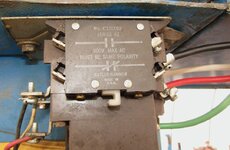
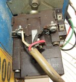
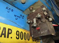
I did get some pics of the contactor.
Wired it matching the old cord but not overly confident this is correct?
It also appears someone added an Up switch that is not original, not sure where that wires in.

Need to run the motor to extend the ram so that I may access the lift base in order to install the chain end.
With that done I will be able to determine exactly how far apart to place the columns and complete the install.
 

Attachments

  • IMG_3586.jpeg
    IMG_3586.jpeg
    253.5 KB · Views: 28
  • IMG_3585.jpeg
    IMG_3585.jpeg
    414.1 KB · Views: 23
  • IMG_3584.jpeg
    IMG_3584.jpeg
    334.4 KB · Views: 23
  • IMG_3583.jpeg
    IMG_3583.jpeg
    282.3 KB · Views: 33
OP
R

R3 Fab

Member
Joined
Oct 31, 2023
Messages
16
What I posted pics of is copied from what was there.
I thought that green was supposed to be ground?
As said, I have little confidence in what was done by the last user of the lift.
So far I have not been able to locate anyone locally who knows these systems.
 
Last edited:
OP
R

R3 Fab

Member
Joined
Oct 31, 2023
Messages
16
Okay, pretty sure I am getting closer.
Factory manual appears to show circuitry that includes a Transformer?
And a four post terminal strip.
Neither of which exist on my lift.

Pretty certain I did correct wires that had previously been wrong.
Green is now grounded, white is now the center leg.
For the life of me I cannot find out what the lowest pair of terminals on the contactor power in side are for.
They do not have continuity with any of the power taps.
Attaching a pic of what I have now.

Also replaced the shattered terminal strip at the motor.

Need some 12-14 GA wire to complete the connection to the motor.

I think terminals 2 and 3 Normally Open activate the contactor.
So unless it is imperative that I add a transformer a trip to the big city should allow me to buy some wire that is not 16 GA appliance cord.
Then wire in to a NO switch and the machine end will be complete.
I cannot seem to attach the schematic from the factory manual.

Still looking for certainty on grounding the generator end.
 

Attachments

  • IMG_3601.jpeg
    IMG_3601.jpeg
    408.7 KB · Views: 19
  • IMG_3602.jpeg
    IMG_3602.jpeg
    286.2 KB · Views: 17
  • IMG_3603.jpeg
    IMG_3603.jpeg
    260.8 KB · Views: 17

wyliesdiesels

Well-known member
Joined
Aug 14, 2012
Messages
20,074
Location
Modesto, CA
green appears to be connected to the contactor coil terminal. there shouldnt be a grounding terminal on the top of the contactor
 
OP
R

R3 Fab

Member
Joined
Oct 31, 2023
Messages
16
Green has to go somewhere, right now I have it grounded to a mounting bolt/the machine frame.
Hoping the parts place may be helpful in the morning.
 

wyliesdiesels

Well-known member
Joined
Aug 14, 2012
Messages
20,074
Location
Modesto, CA
Green has to go somewhere, right now I have it grounded to a mounting bolt/the machine frame.
Hoping the parts place may be helpful in the morning.
the green conductor in image 3584 on post #20 appears to go to a terminal on the contactor NOT a mounting bolt.
 
OP
R

R3 Fab

Member
Joined
Oct 31, 2023
Messages
16
It has been moved, post 23, pic 3601
Finding it impossible to obtain documentation for this contactor despite still being sold.
 
OP
R

R3 Fab

Member
Joined
Oct 31, 2023
Messages
16
OK, I think I am close to finishing this.
Both grounds are connected together within the generator, so unless warned otherwise I will run from the lug at the end of the generator housing to the ground rod.
I can add a second ground rod when funds allow.

I am confident that I have the 3Ph. legs wired correctly at the lift.
That just leaves energizing the contactor to activate the motor.
Terminal #2 and #3 are Normally Open.
The Black/L1 line has a handy second terminal that can make the short run to terminal #2.
Terminal three to a push-button switch, the other side of the switch to ground, corect?
So pushing the button should activate the contactor, or have I made an error?

Have to get this finished in order to lift the arms enough to attach the chains.
Then determine how far apart the columns go.
Then I may finally get this lift installed for use.
 

wyliesdiesels

Well-known member
Joined
Aug 14, 2012
Messages
20,074
Location
Modesto, CA
OK, I think I am close to finishing this.
Both grounds are connected together within the generator, so unless warned otherwise I will run from the lug at the end of the generator housing to the ground rod.
I can add a second ground rod when funds allow.

I am confident that I have the 3Ph. legs wired correctly at the lift.
That just leaves energizing the contactor to activate the motor.
Terminal #2 and #3 are Normally Open.
The Black/L1 line has a handy second terminal that can make the short run to terminal #2.
Terminal three to a push-button switch, the other side of the switch to ground, corect?
So pushing the button should activate the contactor, or have I made an error?
no the other side of the coil shouldnt go to ground. it should either go to the other ungrounded conductor or neutral.

do you know what the coil voltage is on the contactor?
Have to get this finished in order to lift the arms enough to attach the chains.
Then determine how far apart the columns go.
Then I may finally get this lift installed for use.
 
OP
R

R3 Fab

Member
Joined
Oct 31, 2023
Messages
16
OK, white/L2 is neutral.
So black /L1 to the contactor.
Other side of the contactor to a switch.
Switch to white/L2 neutral.
Have to buy a little more wire today.
 

wyliesdiesels

Well-known member
Joined
Aug 14, 2012
Messages
20,074
Location
Modesto, CA
OK, white/L2 is neutral.
So black /L1 to the contactor.
Other side of the contactor to a switch.
Switch to white/L2 neutral.
Have to buy a little more wire today.
but before you do that, you need to confirm what the voltage rating is on the coil. if its 240v rated and you apply 120v it wont work. if its 120v rated and you apply 240v you can cook it.
 
OP
R

R3 Fab

Member
Joined
Oct 31, 2023
Messages
16
Naturally nothing on the contactor states what voltage I need to activate it.
Wiring is all "Done*" now.
I even added a panel fuse to one leg of the switch.
Need to get more fuses.

*Now I just have to get some propane to be able to run the generator and check voltages.
 
To avoid these ads, REGISTER NOW!
Top Bottom