To avoid these ads, REGISTER NOW!

Building a buggy: nobggrnchvy

OP
B

bggrnchvy

Well-known member
Joined
Nov 14, 2011
Messages
589
Location
Pleasant Hill, CA
Thanks for continuing to share and post!

I would suggest adding a little metal to make a ramp so the new steel isn't such a step.

It as a pretty healthy fillet and a chamfer, combined with the pinion angle up at 7°, it shouldn't be major issue as is.

Keep it up!

Thanks!

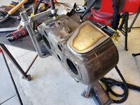
This weekend I started working on the transfer case. The patient is a Ford NP205 of 1977 vintage. It belonged to a friend that has since passed, he was going to build a BW4401/205 doubler for his '96 K3500. Another friend got it from that friends father and gifted it to me to use here.

20220319_132913.jpg

It has no output shaft and is a little rough.

Step one, tear it down.

20220319_142350.jpg

Down to bare case, it was time to make a slight alteration.
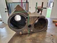
20220319_160710.jpg
20220320_133338.jpg
20220320_142012.jpg

Previously I bought a cheap heated ultrasonic cleaner primarily because of the poor relationship small carburetors and CA gas have. However, I tossed most of the parts from this case in and between 140°F, 50/50 Simple Green/H2O and 5-10 minutes of ultrasonic transducer influenced party time it removed a majority of surface contaminants.

20220320_143501.jpg
20220320_180534.jpg

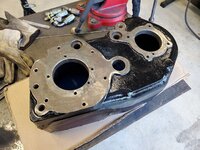
Before the end of the weekend, I masked off the case and got it painted. Hopefully, if the missing bearings show up, I can rebuild the case with the ORD Magnum in front of it next weekend.
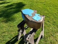
20220320_160022.jpg
20220320_182220.jpg
 
To avoid these ads, REGISTER NOW!
OP
B

bggrnchvy

Well-known member
Joined
Nov 14, 2011
Messages
589
Location
Pleasant Hill, CA
Some minor progress the last couple months.

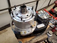
I did build the doubler. I incorrectly added the input shaft seal and retainer, it's not needed on this later revision Magnum. It was removed before I married the two. I am waiting for NWF to finish prototyping their new titan shorty output for the 205 so I can shrink my overall length before I build out the rear output.

20220402_182240.jpg
20220404_175743.jpg

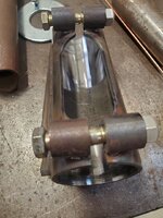
There were a pile of fittings in the box and I think I figured it's to build a combination fill and sight tube so I assembled it as such.

20220404_175752.jpg

I turned down the ring gear to 10.050" to clear the shaved housing and checked fitment before pulling the carrier back out, loctiting and torqueing all the ring gear bolts (which I remembered to buy some prior to needing them since they don't come in the rebuild kits).

20220430_180940.jpg

Pinion support bearing got tapped into place, bearing/bushing driver kit comes in handy.

20220501_183352.jpg

Then I started to build the pinion support. It got torn down, cleaned up and had new races installed and an oil seal so I could start playing with pinion bearing preload.

20220501_133301.jpg

I opted for a crush sleeve eliminator so it is a game of swapping shims to the right overall height. I started at the thickness of the old crush sleeve and have been slowly adding and recombining to get the right preload. Still not there yet as of last night. Mark Williams hardened flange yoke there. The old nut is being used for the different preload attempts with plenty of anti seize on the pinion threads. When I get it locked in I will put the new deformed nut on.

20220501_133247.jpg
20220501_145507.jpg
 
OP
B

bggrnchvy

Well-known member
Joined
Nov 14, 2011
Messages
589
Location
Pleasant Hill, CA
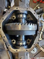
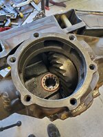
I was one more setup away on the pinion preload. It's tight, right at 35in/lbs, so break in will have to be slow. Backlash is tight as well, on purpose, at .004" so it all works together I guess. A couple neighborhood rides when it all runs with dino oil before putting some 250wt synthetic in there should get everything lapped in. It felt good to torque the caps the final time, it's just too bad the tube of Right Stuff I had failed so I couldn't get the cover on.

20220522_142459.jpg
20220522_120753.jpg
20220522_140907.jpg
 
OP
B

bggrnchvy

Well-known member
Joined
Nov 14, 2011
Messages
589
Location
Pleasant Hill, CA
You're right, 35 in/lbs of pinion preload and .004" B/L seem a bit tight.
These diffs are getting setup using the Carl Jantz theory for offroad gearset longevity.

Tight BL to account for carrier and pinion (not so much in a 14 bolt) deflection with 42" tires being pushed by an 81:1 crawl ratio and 500ft/lbs. He actually suggest .002, which I might do on the front end with the smaller 10" gear set and lack of 3rd pinion bearing. The pinion preload is tight, but it's still in spec for new bearings and will give the roller elements all race surface they can handle.

The break in will just have to be....judicious.
 

zmotorsports

ALLIANCE MEMBER
Joined
Oct 20, 2009
Messages
21,441
Location
Northern Utah
These diffs are getting setup using the Carl Jantz theory for offroad gearset longevity.

Tight BL to account for carrier and pinion (not so much in a 14 bolt) deflection with 42" tires being pushed by an 81:1 crawl ratio and 500ft/lbs. He actually suggest .002, which I might do on the front end with the smaller 10" gear set and lack of 3rd pinion bearing. The pinion preload is tight, but it's still in spec for new bearings and will give the roller elements all race surface they can handle.

The break in will just have to be....judicious.

Gotcha.

Most of my setups are dual purpose (street/trail) but when was racing I crowded the B/L a bit but stayed more in the middle of the pinion preload. On the carrier preload I would also go just a bit tighter to keep the gears meshed under high torque situations.
 
OP
B

bggrnchvy

Well-known member
Joined
Nov 14, 2011
Messages
589
Location
Pleasant Hill, CA
Progressing on multiple fronts the last month.

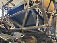
The fuel tank was a dilemma. The tank Goatbuilt makes is 18 gallons, which is a good amount but light for a long trip with a heavy buggy and healthy 6.0L and I hate carrying extra fuel cans. The space between the two vertical bars is right at 22.5" too so I can't recess almost any larger tank into that area either as they start at 24" wide. After measuring and researching quite a bit, I gambled on this RCI circle track wedge style tank fitting and boy does it! 26 gallons listed capacity and I'll probably be using one of Drew's adapter plates for both a GM drop in pump I'll add a Hydromat to and remote fill.

20220613_195547.jpg
20220613_195554.jpg

With the cell acquired, I needed to build some struct underneath for mounting and to protect it from damage. Two old tubes form the first XL chassis rear got chopped up and coped to fit. Coping them to fit made me miss all the laser cut goodness from the kit, I do not miss hand fitting tubing.

20220618_150604.jpg
20220618_161849_001.jpg
20220618_164352.jpg

To help me make the plan for fuel cell mount/skid, coilover and bypass upper mounts and storage panels, I modeled the chassis rear section and I've just started doing some sheet metal. I'll get it all shot out and broken so I can dimple and add nutserts and hopefully buy myself some time ahead.

Trunk_Area_ISO_Top(1).jpg
Trunk_Area_ISO_Bottom(1).jpg

Fuel cell aside, the lower shock and link mounts were cleaned/prepped and welded out.

20220625_140053.jpg
20220618_134220.jpg

I pulled the used SAW 2.5x16s out of storage, crusty. They need a rebuild, but for the time being they are needed for mockup.

20220625_152100.jpg

A liberal application Harvest Gold, a little time and some water got all the oil off. Add a single coil, an old hardware kit and a fresh set of Fox 2.5x16 3 tubes and we have a mockup. Everything fits!
20220625_161748.jpg
20220626_143731.jpg

I need to solidify some items before I can articulate the rear axle and plan for the bumps, but I think there's going to be plenty of room.
 
OP
B

bggrnchvy

Well-known member
Joined
Nov 14, 2011
Messages
589
Location
Pleasant Hill, CA
Lots of things in the works, but not a whole lot of things happening currently.

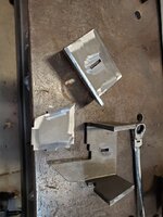
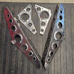
I modeled up the rear (incorrectly, inside to inside and outside to outside are different :rolleyes: ) and had Jason @ECAutoandIronFabrication shoot out some upper shock mounts and a gas tank mount. The plate he ordered was P&O, but by the time it showed up in mill scale they needed to get cut. More work prepping for sure.

RUDSM_ISO_Rev01.jpg
RUDSM_ISO_Rev01_FR.jpg
Trunk_Area_ISO_Bottom(1).jpg

Upper shock mounts fit perfect, really happy there. I do not however see myself doing anymore laminated construction garbage, what a time ****. Side plates should have been straight 1/4" A36 and an 1/8" bridge over the top. Oh well, I'm learning.

20220806_131942.jpg
20220810_231540.jpg
20220814_180546.jpg

The problem is with the gas tank mount. When you draw the vertical tubes as 3.5" closer together than they are because you thought your inside to inside measurement was your outside to outside, the tube reliefs are all messed up and the rosette holes are in the wrong spot, sigh. Fixable, cut up some filler plates, a 1/4" aluminum backing bar and some time with the welder and were fixed. Some more time drill new holes and I'm ready to weld it all together, yay.

20220813_143221.jpg
20220814_180705.jpg

#dimpledietheworld It might be the mid-late 2000s 20 year old on PBB I used to be, but I love the look and feel of useful dimpled holes. The Funbuggy was a favorite. There will be many more holes in this chassis future.
 

Graham08

Well-known member
Joined
Dec 10, 2007
Messages
713
Location
Iron Station, NC
Looks great! I hate mill scale with a passion. I've found that these do a pretty good job of cleaning it off:


I agree on the laminated construction. It's good for adding strength in an area of thinner sheet, but doesn't make a ton of sense when the overlay is nearly the same size as the bracket it's welded to. If you wanted to get fancy with 1/4" plate, you could mill some pockets in it and save as much or more weight.

I dig the dimples, too...I've made several dies in different sizes. I'm always looking for a spot to put a few.
 
OP
B

bggrnchvy

Well-known member
Joined
Nov 14, 2011
Messages
589
Location
Pleasant Hill, CA
Looks great! I hate mill scale with a passion. I've found that these do a pretty good job of cleaning it off:


I agree on the laminated construction. It's good for adding strength in an area of thinner sheet, but doesn't make a ton of sense when the overlay is nearly the same size as the bracket it's welded to. If you wanted to get fancy with 1/4" plate, you could mill some pockets in it and save as much or more weight.

I dig the dimples, too...I've made several dies in different sizes. I'm always looking for a spot to put a few.
A friend has also since recommended those style stripping discs. I've only ever used them before with paint, but it sounds like they are the ticket.

Yea, this was me trying not to have my buddy load 2 material thicknesses on his plasma table for, me not so much a design benefit. Next time, the only way I'm doing it is if the area is much smaller than the overall.
 
OP
B

bggrnchvy

Well-known member
Joined
Nov 14, 2011
Messages
589
Location
Pleasant Hill, CA
Since it has been 7 months, maybe I should update this?

Life got in the way, had to gut and remodel a bathroom, do some major changes to the Dodge, holidays, vacation, work, etc.

I've been stabbing at this when I can and am finally starting to get back on a roll.

The current project(s) is to get the fuel cell mounted and the rear suspension done. To get that rolling I made some PVC mockup links for the rear to work out the bumpstops. Since I wanted bypasses in the rear, bumpstops no longer fit where they are supposed to so I have to design a solution.

With the links figured, I built the uppers (1-1/2" .12w), the lowers will have to wait until I confirm lengths on the front as they will be ordered (2" .25w 4130HT) so lets pay shipping once. No pictures, because, well I forgot.

At least I can bump to droop and flex it in between to see where everything fits.
20230114_160026.jpg
20230114_163449.jpg

Before making the bump pads, I had to figure out a way to mount the bump cans. I drew about 3 iterations until I just decided to see what I could find. Sure enough WOD had a simple kit that I could add a little bit to. They fit together well, but the actual job of fitting up was a pain. A slug of 2" .25w mockup for the stop well and I had a drop of 1-3/4" that stood in for the frame. Then I proceeded to cook them and prove welding is a perishable skill.

20230311_142114.jpg
20230311_155814.jpg

I honed out the ID after burning them together so the bumpstops still slid in nicely.

20230318_181624.jpg

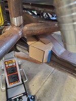
For the bump pads, enter CardboardAD.

20230212_124859.jpg

A little magic dust and a change or two.

Image_1.jpg
20230318_130040.jpg
20230318_130112.jpg
20230318_163553.jpg

Bumps fit, the last part of the puzzle was snugly fitting the rear sway bar. RJ Anti-Rock was pre-designed in from Goatbuilt at the frame side. That fit very nicely. The axle side, I had to some tab making, but I got it very tight and it clears without binding or going over center at droop.

20230325_125712.jpg
20230325_151929.jpg

Thus closes this episode of 10lbs of cr@p in a 5lb bag.

20230325_172430.jpg

We will pick back up soon with how to add too many dimples and tie down a fuel at the same time because some of us are stuck in 2005.

(edited)_20230304_154755.png
 

jjeffries

Well-known member
Joined
Sep 7, 2013
Messages
91
Just read this stem to (present day) stern. It almost hurts my mind, it’s all so clever and well executed. That you can maintain your focus and stay with it amazes me. On a logistics note, I was wondering how much industrial ie welding gas you go through? Must be a lot.

Huge respect and admiration,
John
 
OP
B

bggrnchvy

Well-known member
Joined
Nov 14, 2011
Messages
589
Location
Pleasant Hill, CA
Just read this stem to (present day) stern. It almost hurts my mind, it’s all so clever and well executed. That you can maintain your focus and stay with it amazes me. On a logistics note, I was wondering how much industrial ie welding gas you go through? Must be a lot.

Huge respect and admiration,
John
John, I cannot take most of the credit. Up until the last few steps I was just the monkey following directions and welding what was predesigned and built.

I clearly lost my focus the last few months in fact, but I think I have regained some clarity.

For welding gas, when I was cranking along it was not too bad, maybe 80cuft of AR a month or a little more. I do enough work with the local welding supply they swapped out my owner 80cuft for a 250cuft late last year and I am still working on that volume.
 

rattle_snake

Well-known member
Joined
Jun 25, 2015
Messages
5,221
Location
Chandler, AZ
Nice solution on the bump mount. perishable skill yes, but still better than me.
How are you going to mount the bypasses? trailing arm or on the axle?
 

Bigblue&Goldie

Well-known member
Joined
Mar 12, 2009
Messages
10,706
Location
AZ
I'm curious what you used to hone the can mounts?

I wish I had the pictures, but one of the fabricators and Mason Motorsports showed his process for welding bump stop cans and it was no joke. He had a multi-piece aluminum mandrel that he installed prior to welding to maintain shape and act as a heat soak. The cans slid in and out with ease. Incredible.
 
OP
B

bggrnchvy

Well-known member
Joined
Nov 14, 2011
Messages
589
Location
Pleasant Hill, CA
Nice solution on the bump mount. perishable skill yes, but still better than me.
How are you going to mount the bypasses? trailing arm or on the axle?

Bypasses are just going on the axle. 2.5 coilovers (which I had) means I can't really tune a motion ratio well at this kind of weight/use because of springs.

I'm curious what you used to hone the can mounts?

I wish I had the pictures, but one of the fabricators and Mason Motorsports showed his process for welding bump stop cans and it was no joke. He had a multi-piece aluminum mandrel that he installed prior to welding to maintain shape and act as a heat soak. The cans slid in and out with ease. Incredible.
Just a 2" flap wheel on a 1/4" die grinder. Just had to knock off any high spots, took maybe a minute per can.

If I was doing this often, I could see the benefit of some special fixturing. The chunk of .25"w DOM I stuck in there worked ok, but like you see I still had to do some cleanup.
 
OP
B

bggrnchvy

Well-known member
Joined
Nov 14, 2011
Messages
589
Location
Pleasant Hill, CA
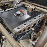
I needed to mount the fuel cell and while a couple straps or pieces of angle and some threaded would suffice, I couldn't get myself to do it. I wanted to integrate as much in the way of common mounting points to unitize the rear and add some cohesiveness. I took measurements and drew up a solution I think I liked. The side plates tie into the vertical tube towards the front with a cross drilled and sleeved hole (yet to be added), the base plate the fuel cell fits on, and the support rails for the rear area sheet metal (yet to be added) while also mounting through fuel cell can.

Trunk_Area_Fuel_Cell_Mount.jpg

I sent the flat patterned files to EC Auto and Iron Fab and Jason shot them out on his plasma and was kind enough to bend up the 14ga on his brake. Biggest brake I have access to is 24" and these parts are ~27" long sadly. After a little work with the surfacing disc, they were ready to form.

IMG_20230403_085047_538.jpg IMG_20230403_085047_582.jpg

I was about 4 dimples in when my compressor started hissing and I lost pressure. The pressure switch diaphragm wore through and killed the air over hydro ram on the press. Hand pumping the press ram makes you appreciate every dimple a little more I think.

After that I burned formed ends together and then added some weld washers to the main bolt holes to reinforce the 14ga. I test fit them, and found I had to make a modification in the rear to fit the vertical tubes on the chasses, but then they dropped right on. The space at the mating flange of the upper and lower fuel cell shell currently being taken up by washers will get a turned full diameter spacer. I just need to get the upper fuel cell mount full mounted and tightened down to see how it affects the distance there.

IMG_20230403_085047_516.jpg IMG_20230403_085047_440.jpg IMG_20230403_085047_472.jpg

I started making the angle support rails to mount the very rear of the fuel cell mounts, but for some reason have lost my tube notcher, so instead I spent the day mirroring the bump pad/bump can mount and sway bar to the driver side. Hoping to get some work on finishing the fuel cell mounts next weekend.
 
OP
B

bggrnchvy

Well-known member
Joined
Nov 14, 2011
Messages
589
Location
Pleasant Hill, CA
I was out on vacation the last few weeks, but I did manage to make some progress just prior. I finished mounting the fuel cell, the only part left is the cooler rack over the top to come in future.

I took a piece of 1-1/2" .095w box and cut/coped it to fit and burned it in to act as a secondary plan to clamp to. At the same time I laid out some holes, cross drilled the vertical tubes and welded in sleeves to receive 3/8" bolts which capture the front of the upper fuel cell mounts.

20230408_162540.jpg
20230408_162614.jpg

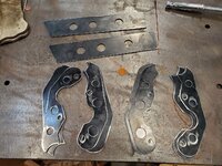
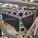
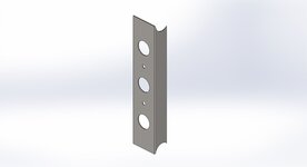
Those in I drew the parts I wanted to lock in the backside. These 4 parts capture both the fuel cell mounts and will act as the middle supports for the rear sheet metal.

ar_Fascia_Fuel_Cell_Cupport_vN1BthGgWcqFCsoLkKaR5p.jpg

Parts came in and got dimpled, had rivnuts added for future sheet metal and got burned together.

20230415_181840.jpg

Then they slid into place, got marked for level/plumb and clearance and got burned in themselves.

20230415_184056.jpg

There is not a lot of clearance.

20230415_185016.jpg
20230415_184204.jpg

But I am pretty pleased with how the system came out.

20230415_185042.jpg

Need to finish burning in the other side, then time to pull the rear axle out for bump pad and sway bar mount weld out.
 
To avoid these ads, REGISTER NOW!

kbs2244

Well-known member
Joined
Nov 11, 2006
Messages
14,065
great build
one suggestion
the close up PICs are great but throw in a few showing where they fit in the over all build
you are a case of "can not see the forest, for the trees"
 
OP
B

bggrnchvy

Well-known member
Joined
Nov 14, 2011
Messages
589
Location
Pleasant Hill, CA
I keep running into situations where the regular standby pipe jacks are difficult to use to adjust buggy height. The adjuster spins in axis with the support leg, so you need to make sure you have clearance, but the legs spread out so much at the bottom putting two next to each other in the width of the buggy is difficult.

Somebody, who I wish I could recall, showed me this kit Brennan Metcalf makes called the Tauler Jack. It converts a trailer tongue jack into a Hi-Lift of sorts.

Tauler Jack

So I ordered the kit and Curt jack, stripped the paint off the jack on one side, prepped the precut pieces and fit it together, burned it in, and gave it a coat of paint. It's already been very useful in the garage and I think I'll make a mount for it on the buggy in lieu of the old Hi-Lift from the Chevy.

20230429_151510.jpg
20230429_160432.jpg
20230429_161555.jpg
20230507_181532_71Dwt6N8QNNSWt3vhWK6yg.jpg

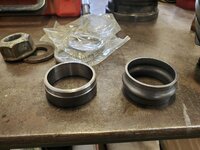
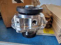
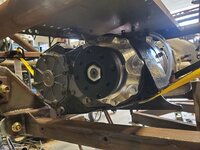
Separately I got all the pieces I needed to finally finish the transfer case assembly, the output housing. You may remember this transfer case had no output housing, shaft or associated low gear. I sourced a used low gear and bearings from Torque King and then got this beautiful piece from Northwest FabWorks.

20230330_114751.jpg

It does 4 things:
-Shortens overall length
-Provides a 1-3/4" 34 spline output shaft that is supported by 2 tapered roller bearings (instead of a single ball bearing like stock)
-Converts the output to a flange yoke (easily done stock, but its included)
-Converts the speedo to GM VSS

So, output received, I installed the low gear with it's 64 individual roller elements which made me appreciate cartridge bearings so much.

20230507_125459_jkAZn9y2fLm8ywDW6Xduff.jpg

Then I got to install the individual rollers in the output itself that align with the input shaft. Another pain in the neck of 40's tech.

Finally with too many types of lube/sealant/thread locker it all got assembled one last time.

20230506_170220_9QMMDjxbpQwhRygxoFioMB.jpg
(edited)_20230507_133017_fy6MCc8Hhu5S6dmE1fCN94.png

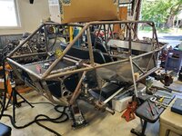
Back to the chassis, insert current overall picture:

20230429_140145.jpg

I added two more tubes in the back to protect the larger fuel tank from driver error. It's just so snug, any rock deciding to play a little pookaboo is going to ruin the day. Later a thin aluminum panel will bolt across to protect the open areas a bit.

IMG_20230510_080428_754.jpg
20230507_141128_pB8SAudXpFgh4REjWj8CZf.jpg

The rear axle is out, again, getting spun around and having all the bumpstop landings and sway bar mounts welded out.
 
OP
B

bggrnchvy

Well-known member
Joined
Nov 14, 2011
Messages
589
Location
Pleasant Hill, CA
I am still alive. Spent last summer building an outdoor space at the wife's request and my dad died pretty suddenly late last year but I am righting the ship and we are headed in the right direction again here.

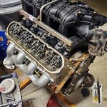
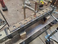
Engine got a genIV manifold because I needed injectors (they were all stuck) and I found the whole thing for cheaper than injectors alone. I also stabbed in a mild Truck Norris cam with some upgraded rockers, springs, and pushrods. I splurged on a timing set it didn't need, replaced the cam thrust plate, put on some LS3 manifolds to fit the GoatBuilt exhaust and I'm sure some other stuff I can't remember.
IMG_20240305_101231_858.jpg
IMG_20240305_101231_910.jpg
IMG_20240305_101231_938.jpg

With my dad's passing I inherited a 3D printer. I printed a clip for the MAP sensor to retain it without the cover.

20240101_172350.jpg

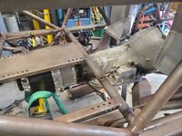
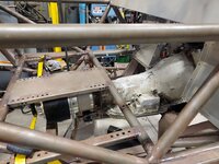
Utilizing the hoist and using the upper cage as a block I lifted the t-case in and married it to an 80e mockup case. There's a Maximum Ultra 4 4l80e and converter sitting in a crate at work to replace it when the time comes. The good news it all seems to fit, snuggly, but well.

20240218_133108.jpg
20240218_142631.jpg
20240218_134918.jpg

I went back and forth to support the middle span from the GM adapter or the Magnum flange and decided to spend more time than I should have an build a small frame that integrated both to a single bushing. The 205 tail shaft is also getting a support straight down to a bushing so there isn't a moment working against the back of the 80 tail housing and hopefully doesn't concentrate torsional stress there as well.

Tried to reuse the opposite ****** bushing from GoatBuilt, but the ears are a little short and it will bottom out. Going to have to redesign that side of it and integrate it into the tubular crossmember. Waiting for the engine to go in and everything to mate up before I spend more time worrying about it.

IMG_20240318_084834_570.jpg
20240317_154929.jpg
IMG_20240318_084834_642.jpg

Last update is the motor mounts, crossmember and oil pan skid are installed and ready for me to drop the engine into it. Just have to figure out how I am going to lift it as the hoist in the shop is 4' off center of the engine bay. Might need to borrow the mini excavator.

20240324_170727.jpg
20240219_143144.jpg
 
OP
B

bggrnchvy

Well-known member
Joined
Nov 14, 2011
Messages
589
Location
Pleasant Hill, CA
Sorry to hear about your dad's passing.

Glad you are able to make some progress and share with us.
Thank you.

My condolences. My father passed in late November.
Thank you and I am sorry to hear that. It is a curious thing that I have had to describe to my wife. It is such a non-unique feeling, parents have been passing since people were people (whenever or where ever that was), but the pain and loss is so solitary.

My dad was not much for dwelling and more making a plan and moving forward. So in that vein I am making a plan to get this project done so I can take the kid on some adventures.

I borrowed an engine hoist and got the engine stabbed in. Had to go backwards a bit to go forwards. Luckily the chassis is light enough I can drop it to the floor with a single floor jack to get the oil pan over the front upper crossmember.

IMG_20240401_075751_612.jpg
IMG_20240401_075751_636.jpg
IMG_20240401_075751_535.jpg
20240331_192410.jpg

No spiffy valve covers, stockers are all that fit. Probably for the best :ROFLMAO:

Now to mount the rest of the drivetrain.
 
OP
B

bggrnchvy

Well-known member
Joined
Nov 14, 2011
Messages
589
Location
Pleasant Hill, CA
Goal for the weekend was to get the drivetrain attached.

20240413_173123.jpg

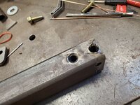
I drilled out and sleeved the mounting holes for the ****** crossmember.

20240414_114519.jpg

Then the repurposed Goatbuilt bushing mount got chopped up and burned it. Thank you for easy bench fillet welds to make me look like the welder I am not.

20240414_124746.jpg

Then it got bolted in place, and compressed with a floor jack and the tabs burned to the frame.

IMG_20240415_074143_179.jpg

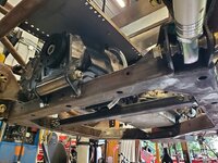
As you can see in the last picture I also cut down the NWF tail housing mount and made some tab edits to fit. Note to self, when you use a floor jack to set clearances, block them out as the jack may bleed down overnight and you might weld it all in just to find out you need to add 5/16":confused:

20240414_141512.jpg
20240414_152705.jpg
20240414_182505.jpg

Then there was the rinse/repeat of prepping some 1-1/2" .120w for the uppers and burning them together.

IMG_20240415_074142_996.jpg
20240414_183657.jpg

That let me get the front axle actually under the rig just before I had to call it quits. I ordered the lower links, they should be in a week or two and then I can get to work on the front suspension.
 
OP
B

bggrnchvy

Well-known member
Joined
Nov 14, 2011
Messages
589
Location
Pleasant Hill, CA
20240505_163621.jpg
20240505_163613.jpg

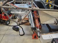
Front bump cans mocked up using a drop of 2" .25w tube.

20240505_134328.jpg

Goatbuilt winch fairlead mount in place with a Brennan's Garage fairlead.

20240505_163825.jpg
20240505_122642.jpg

Trying to do a better job of wiring on this rig than the last one. Old dirty cooler is just to show what they come from the factory like, that was the PS cooler out of the last rig. The clean one is the transmission cooler for this rig and I prepped the pigtail with a Deutsch connector used kapton underneath to strain relieve the wires a little and stuck the loom in place with some adhesive lined heat shrink. Then mounted the Deutsch connector to the fan shroud which hopefully keeps the wires from breaking off at the motor side. It's no Bonneville car, but hopefully I can keep the sparky gremlins at bay.

20240504_172559.jpg

4130 treated lowers came in. I just finished boring the high misalignment spacers out to fit the 5/8" bolts (I got a pile of 9/16" HMS's from a friend) so I can get the rods ends to fit the tabs. Hopefully have them in shortly.
 
OP
B

bggrnchvy

Well-known member
Joined
Nov 14, 2011
Messages
589
Location
Pleasant Hill, CA
20240512_174554.jpg

All the links are in and they fit with a couple of threads showing.

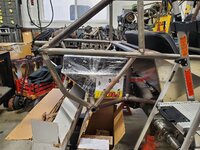
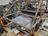
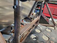
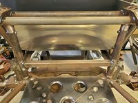
There's a big space between the fuel cell and the back of the rear seats that's open to air on 4 sides, but impossible to really get to. It tapers from the top so it's bad for storage, the shocks are on both sides so access is pretty terrible and the rear truss comes up at full bump and eats the lower few inches. It seems like a good spot for a cooler, hopefully I can get some air flow from under the rig and then out the top/sides. It may need a duct to direct the air out and up after the fan pulls it through to cooler to keep it from recirculating and killing the efficiency.

I grabbed some scrap 10ga 304 plate and made some fast and dirty mounts with the iron worker. Not to self, the .5 in 7.5" spacing matters and should not be forgotten or you get to drill extra holes.

20240511_163031.jpg20240511_163020.jpg

After tacking it in, I pulled the rear seat and panels to weld the mounts out and then put the cooler in. I need to probably put some PEM nuts in, getting the nuts on the backside isn't terrible, but it isn't easy.

20240512_144517.jpg

Finally got the tube disconnects into the over engine crossmember, now that I know about where they needed to sit width wise. I added a 1/8" to get the fit in the nodes tighter.
20240512_160038.jpg
20240512_175544.jpg
 

Bodj Built

Well-known member
Joined
Feb 3, 2016
Messages
1,167
Location
Moorpark, CA
Lookin good! I think you'll be fine with the cooler down there, so long as it doesn't get caked with mud being down low. A lot of prerunners mount them behind the cab, and it's fine for low speeds, but high speeds creates a vacuum behind the cab and the efficiency plummets.
 
OP
B

bggrnchvy

Well-known member
Joined
Nov 14, 2011
Messages
589
Location
Pleasant Hill, CA
Lookin good! I think you'll be fine with the cooler down there, so long as it doesn't get caked with mud being down low. A lot of prerunners mount them behind the cab, and it's fine for low speeds, but high speeds creates a vacuum behind the cab and the efficiency plummets.
We will have to see. It's a looser converter and I tend to drive with a heavy foot, hope the air flow can keep up.
 
To avoid these ads, REGISTER NOW!
Top Bottom