To avoid these ads, REGISTER NOW!

Can I reverse this motor with drum switch?

BD55

Well-known member
Joined
Aug 15, 2011
Messages
219
Location
Northern Utah
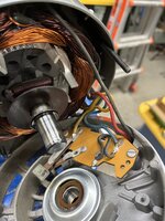
Trying to see if this motor can be reversed with the drum switch I have to power my Atlas 12” lathe. Motor plate says to switch red and black wires in order to reverse, but I want to do that with the drum switch. IMG_0899.jpeg
IMG_0901.jpeg
Here’s what the back side of the board looks like.
IMG_0900.jpeg
Here’s what the switch looks like.
IMG_0894.jpeg
Furnas A14 switch.

If this no worky no matter what, I have a less desirable motor I can use that will work.
 

Attachments

  • IMG_0894.jpeg
    IMG_0894.jpeg
    631.2 KB · Views: 24
To avoid these ads, REGISTER NOW!

larry_g

Well-known member
Joined
Apr 28, 2007
Messages
16,889
Location
oregon
Yes you can IF you have the correct drum switch. Drum switches come in a variety of configurations and you have to have one that you can configure to do what you want.

lg
no neat sig line
 

Gozo

Well-known member
Joined
Oct 10, 2013
Messages
251
Location
Central VA
Or you could have the drum switch fire a DPDT relay to electrically swap the red and black. At 12 amps, I’d call it a contactor rather than a relay though.
 

American Locomotive

Well-known member
Joined
Jan 8, 2017
Messages
10,989
Location
Rhode Island
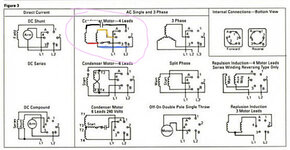
Yes it will work, where does the black wire go? Does it go up to the capacitor?
 

Attachments

  • 195220-db18eab011d1b6010db87d1bbdd13e50.jpg
    195220-db18eab011d1b6010db87d1bbdd13e50.jpg
    34.4 KB · Views: 33

PCustoms

Well-known member
Joined
Jul 23, 2011
Messages
23,230
Location
VT
Or you could have the drum switch fire a DPDT relay to electrically swap the red and black. At 12 amps, I’d call it a contactor rather than a relay though.

Am I missing something in the wiring diagram?
 
To avoid these ads, REGISTER NOW!

American Locomotive

Well-known member
Joined
Jan 8, 2017
Messages
10,989
Location
Rhode Island
If my thinking is correct, it is possible, but you will need to make some minor wiring modifications to the motor. You will need a cord with 5 wires (4 current carrying conductors + ground)

The Blue and Yellow wires are the main motor windings (L1 and L2)
The Red wire goes to the start winding
The Black wire goes to the capacitor

Basically you will need to unsolder that yellow wire (L1) from the start switch, and run it up separately to the "4" post of your drum switch.
The blue wire can remain on that screw terminal on the motor. The terminal the blue wire is connected to must connect to "2" on the drum switch.

The black wire going to the capacitor must connect to "1" on the drum switch.

The red wire in the motor is an internal start winding wire. It must connect to the start switch, so it must go to terminal labeled 3 on the motor (where the black wire is now).

Finally, the bottom screw terminal (which no longer has the yellow wire connected to it, just the start switch), must be connected to terminal "3" on the drum switch.
 

Attachments

  • 195220-db18eab011d1b6010db87d1bbdd13e50.jpg
    195220-db18eab011d1b6010db87d1bbdd13e50.jpg
    187.9 KB · Views: 37
To avoid these ads, REGISTER NOW!
Top Bottom