To avoid these ads, REGISTER NOW!

How to size Nickel Strips for Battery Pack?

YoshiMoshi3

Well-known member
Joined
Nov 2, 2022
Messages
502
My BMS for my Makita battery pack that I got off Ali has a max continuous discharge of 40 A, and a max instanteous current of 80 A. Do I size my nickel strips to handle 40 A or 80 A? I'm using a 5S3P configruation of 21700 cells. I have found various charts online for current ratings of nickel strips.
1729901466739.png
I see that most cheap spot welders have difficulty spot welding nickel strips thicker than 0.15 mm. So I could use 0.15 mm x 12 mm nickel strips which are optimal for 17 A.
If I assume I'm design a battery for 40 A (over 80 A) then I would need at least three strips thick.
(40 A/17 A/strip) ~ 2.35 strip
So I need at least three strips for the series connections. But what size should I use for the parallel connections, how much current do they carry?

What size nickel strip should I use for the BMS connections for charging (not battery negative or battery positive)? How much current do these strips need to handle? This is B1, B2, B3, and B4 in the image below.


Could I just use wider nickel strip? How for example do I calculate the optimal current for 0.15 mm x 14 mm nickel strips?

Thanks for any help on this.

1729903020367.png1729903610294.png
 
Last edited:
To avoid these ads, REGISTER NOW!

Rabid Badger

Well-known member
Joined
Apr 2, 2018
Messages
1,338
My BMS for my Makita battery pack that I got off Ali has a max continuous discharge of 40 A, and a max instanteous current of 80 A. Do I size my nickel strips to handle 40 A or 80 A? I'm using a 5S3P configruation of 21700 cells. I have found various charts online for current ratings of nickel strips.
1729901466739.png
I see that most cheap spot welders have difficulty spot welding nickel strips thicker than 0.15 mm. So I could use 0.15 mm x 12 mm nickel strips which are optimal for 17 A.
If I assume I'm design a battery for 40 A (over 80 A) then I would need at least three strips thick.
(40 A/17 A/strip) ~ 2.35 strip
So I need at least three strips for the series connections. But what size should I use for the parallel connections, how much current do they carry?

What size nickel strip should I use for the BMS connections for charging (not battery negative or battery positive)? How much current do these strips need to handle? This is B1, B2, B3, and B4 in the image below.


Could I just use wider nickel strip? How for example do I calculate the optimal current for 0.15 mm x 14 mm nickel strips?

Thanks for any help on this.
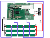
1729903020367.png1729903610294.png
1) Your chart lists continuous ratings. You can go ahead and match it to the continuous rating of your battery.

2) You don't need to stack the strips. You can do one series connection between each parallel set of cells and match exceed the continuous rating of your BMS.

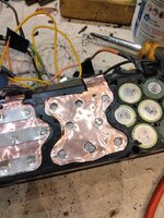
3) The strips included with your kit are more than sufficient for balancing and parallel connections. You can overlay additional nickel strips over the included steel strips like I did here:

IMG_20241026_130754.jpg

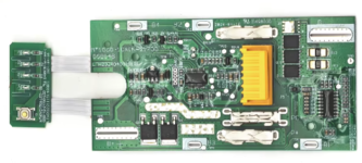
4) You really should have stuck with the battery kits I recommended. That first board has numerous deficiencies, the second one is a fire waiting to happen. Dividing the cells between 6 batteries instead of 4 is a small price to pay for proper battery management. The total price difference would have been about $10.
 
Last edited:

mattthemuppet

Well-known member
Joined
Dec 9, 2023
Messages
245
Location
San Antonio TX/ Spartanburg SC
Just out of curiosity, why are the nickel strips above not spot welded to the batteries directly?

As for current capacity, it’s all about cross sectional area and conductivity. If you want to scale up from 1.5*12 to 1.5*14, just work out the change in cross section and multiply the current capacity by that
 

Rabid Badger

Well-known member
Joined
Apr 2, 2018
Messages
1,338
Just out of curiosity, why are the nickel strips above not spot welded to the batteries directly?

Folding the nickel down into those recesses wasn't practical or necessary, given the cross section of the material already connected to the batteries.
 
OP
Y

YoshiMoshi3

Well-known member
Joined
Nov 2, 2022
Messages
502
1) Your chart lists continuous ratings. You can go ahead and match it to the continuous rating of your battery.

2) You don't need to stack the strips. You can do one series connection between each parallel set of cells and match exceed the continuous rating of your BMS.

3) The strips included with your kit are more than sufficient for balancing and parallel connections. You can overlay additional nickel strips over the included steel strips like I did here:

IMG_20241026_130754.jpg

4) You really should have stuck with the battery kits I recommended. That first board has numerous deficiencies, the second one is a fire waiting to happen. Dividing the cells between 6 batteries instead of 4 is a small price to pay for proper battery management. The total price difference would have been about $10.
1) Thanks for the reply. I remember your battery and BMS can be found here: https://www.aliexpress.us/item/3256806803364276.html.
What is the rated discharge current for the BMS?
1730000497160.png

2) The original BMS I was going to use: https://www.aliexpress.us/item/3256...t_main.17.366d1802IIds6W&gatewayAdapt=glo2usa
standard discharge current: 25-35 A
1730000458537.png

3) An improvement BMS I was considering, 15 cell 21700 version: https://www.aliexpress.us/item/3256...st_main.5.366d1802IIds6W&gatewayAdapt=glo2usa
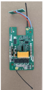
This one was rated for 40 A continuous, 80 A instantaneous
1730000554846.png

Why do you think the third BMS is a fire hazard? I think it's better than BMS 2 with lower discharge current rating.

I'm just really trying to understand this here, that's all, and learn as much as possible.

I think the plates that come with most kits are nickel plated steel. I was thinking that pure nickel strips would be better for conducting current. Copper strips would be the best, but spot welding copper isn't really something easy to do. Most cheap welders can spot weld 0.15 mm thick nickel. You would need an expensive one to spot weld thicker ones, and they don't seem to go thicker than 0.30 mm thickness of nickel.

I guess it depends on what chart you look at, 0.15 mm x 8 mm nickel strips, I would need 4 layers to get to 40 A. There are some things that I don't understand about ampacity, and where the values in those tables come from. They don't seem to take into consideration the length of the conductor. It seems to create an electrical circuit model for thermal heat disipation, and is not to easy to understand. I'm getting closer though in trying to understand the math behind it.
 

Rabid Badger

Well-known member
Joined
Apr 2, 2018
Messages
1,338
1) Thanks for the reply. I remember your battery and BMS can be found here: https://www.aliexpress.us/item/3256806803364276.html.
What is the rated discharge current for the BMS?
1730000497160.png

2) The original BMS I was going to use: https://www.aliexpress.us/item/3256...t_main.17.366d1802IIds6W&gatewayAdapt=glo2usa
standard discharge current: 25-35 A
1730000458537.png

3) An improvement BMS I was considering, 15 cell 21700 version: https://www.aliexpress.us/item/3256...st_main.5.366d1802IIds6W&gatewayAdapt=glo2usa
This one was rated for 40 A continuous, 80 A instantaneous
1730000554846.png

Why do you think the third BMS is a fire hazard? I think it's better than BMS 2 with lower discharge current rating.

I'm just really trying to understand this here, that's all, and learn as much as possible.

I think the plates that come with most kits are nickel plated steel. I was thinking that pure nickel strips would be better for conducting current. Copper strips would be the best, but spot welding copper isn't really something easy to do. Most cheap welders can spot weld 0.15 mm thick nickel. You would need an expensive one to spot weld thicker ones, and they don't seem to go thicker than 0.30 mm thickness of nickel.

I guess it depends on what chart you look at, 0.15 mm x 8 mm nickel strips, I would need 4 layers to get to 40 A. There are some things that I don't understand about ampacity, and where the values in those tables come from. They don't seem to take into consideration the length of the conductor. It seems to create an electrical circuit model for thermal heat disipation, and is not to easy to understand. I'm getting closer though in trying to understand the math behind it.

I'm not going to go into the engineering details of each board. You can either take my word that they're inferior/dangerous or not.

The kit I recommended is rated for 60A continuous, with 100A pulses for up to 1 second and 180A for up to 100ms.
 

mattthemuppet

Well-known member
Joined
Dec 9, 2023
Messages
245
Location
San Antonio TX/ Spartanburg SC
Nickel plated steel ***** for both spot welding and conductivity. Length of strip doesn’t really matter (unless you’re getting into feet of it), it’s the cross sectional area that matters

They reduce the resistance of the connections between the battery cells and between the cells and the management board.
but if they don't contact the battery cells directly and are only contacting the end plates then they can only change the resistance of the end plates no? The resistance from the cells to the end plates won't change. It would be like having a small pipe connected to your sink and to your sewer with a big fat pipe in between - flow is limited to whatever can fit through the small pipe. I've just never seen it (or done it) like that, in hundreds of builds.
 
OP
Y

YoshiMoshi3

Well-known member
Joined
Nov 2, 2022
Messages
502
I'm not going to go into the engineering details of each board. You can either take my word that they're inferior/dangerous or not.

The kit I recommended is rated for 60A continuous, with 100A pulses for up to 1 second and 180A for up to 100ms.
That's 20 A increase than the board I found! Where did you find this 60A and 100A rating? I cannot find it on the Ali Express website, specified anywhere?
 
OP
Y

YoshiMoshi3

Well-known member
Joined
Nov 2, 2022
Messages
502
tivity. Length of strip doesn’t really matter (unless you’re getting into feet of it), it’s the cross sectional area that matters

but if they don't contact the battery cells directly and are only contacting the end plates then they can only change the resistance of the end plates no? The resistance from the cells to the end plates won't change. It would be like having a small pipe connected to your sink and to your sewer with a big fat pipe in
I'm trying to understand the engineering behind selecting strip width and thickness, for the current carrying capability. I think most plates that come with battery cases are nickel plasted steel. It looks like most "pure Nickel rolls" on Amazon are also Nickel plated steel.

My concern that I'm seeing at the moment, just for designing packs alltogther is that, lets say that chart from my first post is accurate, which by the way every chart I find has different values, than 0.15 mm x 0.8 mm (most common size) is good for 11.33 A. Than that would mean for a 60 A battery pack, you would need to spot weld 6 strips of that stuff on top of each other to the B- and B+ connections to the BMS. The clearances within the battery pack are very slim, not sure there is room for that much. This is why I was trying to evaluate rolling up nickel around some copper wire of appropriate gauage wire. The ratings from NEC for copper wire, seem to be time tested, and I'd rather trust those values than the tables than the ampacity tables for nickel strips, and every table has different values.

So I was trying to figure out where the numbers come from, but am struggling. It seems like an understanding of both electrical engineering and mechanical engineering is requried. I cannot find a goo explanation on the internet anywhere, just references to tables, and each table has different values.

Most "cheap" amazon spot welders can spot weld up to 0.15 mm thick nickel. Even the "expensive" ones can only spot weld 0.30 mm thickness.

Copper is the most conductive, but spot welding copper, good luck!
 

mattthemuppet

Well-known member
Joined
Dec 9, 2023
Messages
245
Location
San Antonio TX/ Spartanburg SC
here's another idea - sandwich some thin copper sheet between the cells and the nickel strip. You can actually spot weld through the copper sheet if you have a powerful enough spot welder, but I found it more reliable to hole punch out holes for the battery terminals. This is a 40V (10S4P) bike pack. Not as high a power draw as a power tool by any stretch, but it works just as well as a factory pack.IMG20230118194551.jpgIMG20230119182726.jpg
 
OP
Y

YoshiMoshi3

Well-known member
Joined
Nov 2, 2022
Messages
502
here's another idea - sandwich some thin copper sheet between the cells and the nickel strip. You can actually spot weld through the copper sheet if you have a powerful enough spot welder, but I found it more reliable to hole punch out holes for the battery terminals. This is a 40V (10S4P) bike pack. Not as high a power draw as a power tool by any stretch, but it works just as well as a factory pack.IMG20230118194551.jpgIMG20230119182726.jpg
I like this idea! If this was done, no need to worry about the thickness of your nickel strips! How thick nickel did you use and how thick copper sheets did you use? I mean you probably wouldn't even have to worry about using nickel plated steel vs pure nickel. Did you do soemthing similar to the B- and B+ connections?

Do you just use regular scissors to cut the metals?
 
Last edited:

Rabid Badger

Well-known member
Joined
Apr 2, 2018
Messages
1,338
Nickel plated steel ***** for both spot welding and conductivity. Length of strip doesn’t really matter (unless you’re getting into feet of it), it’s the cross sectional area that matters

1) Steel strips are by far the easiest to spot weld. More resistance=more heat for a given electrical input=easier welding.

2) Length absolutely matters when you're talking high currents.

but if they don't contact the battery cells directly and are only contacting the end plates then they can only change the resistance of the end plates no? The resistance from the cells to the end plates won't change. It would be like having a small pipe connected to your sink and to your sewer with a big fat pipe in between - flow is limited to whatever can fit through the small pipe. I've just never seen it (or done it) like that, in hundreds of builds.

Hundreds of builds, without basic knowledge of current flow or geometry. Must be rough.

Look at the shape of the strips. There is a WIDE current path coming off the end of each cell. Almost 35 mm wide, to be exact. Since it expands in a circle, the path widens by 3.14mm every half millimeter farther you get from the cell.

Length of the higher resistance path makes a difference, too. How do you think tiny little mosfets can conduct 100+ amps? That 1.8mm between the cell and the 40mm wide main body of the steel strip, plus 3 nickel strips laid on top is very nearly meaningless.
 
Last edited:

Rabid Badger

Well-known member
Joined
Apr 2, 2018
Messages
1,338
I like this idea! If this was done, no need to worry about the thickness of your nickel strips! How thick nickel did you use and how thick copper sheets did you use? I mean you probably wouldn't even have to worry about using nickel plated steel vs pure nickel. Did you do soemthing similar to the B- and B+ connections?

Do you just use regular scissors to cut the metals?

It is a complete waste of time and materials, dude.
 
To avoid these ads, REGISTER NOW!
OP
Y

YoshiMoshi3

Well-known member
Joined
Nov 2, 2022
Messages
502
It is a complete waste of time and materials, dude.
You might be right. I tried going into the math, and it's basically converting thermal dissipation into an electrical circuit model. So it's not easy. Requires knowledge of both fields.

Were did you find the specifications for your BMS that it was 60 A continuous and 100 A peak? I can't find that in writing anywhere. But I agree that would be a much better BMS than the one I found and I want it if so
 

Rabid Badger

Well-known member
Joined
Apr 2, 2018
Messages
1,338
You might be right. I tried going into the math, and it's basically converting thermal dissipation into an electrical circuit model. So it's not easy. Requires knowledge of both fields.

Were did you find the specifications for your BMS that it was 60 A continuous and 100 A peak? I can't find that in writing anywhere. But I agree that would be a much better BMS than the one I found and I want it if so
1000005045.png
 
OP
Y

YoshiMoshi3

Well-known member
Joined
Nov 2, 2022
Messages
502

Go to "Item Description" click view all and scroll down.
Just out of curiosity, I know you added an extra strip of Nickel in some places as a precaution. Do you estimate that you could have added an extra layer, or was one extra layer all that you could have done and was already rubbing against the plastic case? Also did you use 0.15 mm thick nickel strips?
 
OP
Y

YoshiMoshi3

Well-known member
Joined
Nov 2, 2022
Messages
502
here's another idea - sandwich some thin copper sheet between the cells and the nickel strip. You can actually spot weld through the copper sheet if you have a powerful enough spot welder, but I found it more reliable to hole punch out holes for the battery terminals. This is a 40V (10S4P) bike pack. Not as high a power draw as a power tool by any stretch, but it works just as well as a factory pack.IMG20230118194551.jpgIMG20230119182726.jpg
Why did you need the holes? Could you please elaborate a bit on this?
 

mattthemuppet

Well-known member
Joined
Dec 9, 2023
Messages
245
Location
San Antonio TX/ Spartanburg SC
Same reason why it’s hard to spot weld copper - you need a lot more power if you’re spot welding the nickel to the cell through the copper. Having the hole for the spot weld requires less power and gave more reliable results (solid welds), but still gave most of the benefits
 
OP
Y

YoshiMoshi3

Well-known member
Joined
Nov 2, 2022
Messages
502
Same reason why it’s hard to spot weld copper - you need a lot more power if you’re spot welding the nickel to the cell through the copper. Having the hole for the spot weld requires less power and gave more reliable results (solid welds), but still gave most of the benefits
So the part that comes into conctact with the battery is strictly nickel? Did you use hot glue (looks like it from the picture)?
 

Rabid Badger

Well-known member
Joined
Apr 2, 2018
Messages
1,338
Just out of curiosity, I know you added an extra strip of Nickel in some places as a precaution. Do you estimate that you could have added an extra layer, or was one extra layer all that you could have done and was already rubbing against the plastic case? Also did you use 0.15 mm thick nickel strips?

No, I couldn't have added an extra layer. The pack just barely fit in the case the way I built it, with the strips welded as flat as possible.

My strips are 0.15x8mm.

I did the math on the resistance of the steel between the batteries and the nickel. It comes out to 0.00019 Ohms. Multiplied by 10 connections you get 0.0019 Ohms. At the max rated current of P45B cells (at full charge), you lose less than 2W vs welding the nickel strips directly.
 
OP
Y

YoshiMoshi3

Well-known member
Joined
Nov 2, 2022
Messages
502
No, I couldn't have added an extra layer. The pack just barely fit in the case the way I built it, with the strips welded as flat as possible.

My strips are 0.15x8mm.

I did the math on the resistance of the steel between the batteries and the nickel. It comes out to 0.00019 Ohms. Multiplied by 10 connections you get 0.0019 Ohms. At the max rated current of P45B cells (at full charge), you lose less than 2W vs welding the nickel strips directly.
What you have obviously works. How did you determine that the strips that came with it and 0.15x8 mm was able to carry 60 A continuous? Looking at the Makita factory batteries, I think the maximum one doesn't even output that much. Basically for a portable battery pack, I think would need some thick strips. To thick to fit in the battery pack.

The highest official pack was the 4.0 Ah packs. Which has two possible configurations, with a max continuous discharge of 44 A. It used Sony Murta VTC4 cells.

We know that the mower is 125C insulation wire in series and about 10 AWG. And I think it might actually be 11 AWG or 12 AWG. The measurement was taken with the insulation on, and I think the AWG charts are diameter of the conductor without insulation.
 
Last edited:
OP
Y

YoshiMoshi3

Well-known member
Joined
Nov 2, 2022
Messages
502
I've done some additioanl study into this topic. Posting findings here.
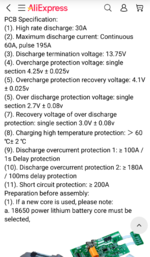
For the "Maximum discharge current: Continuous 60A, pulse 195A"
https://www.aliexpress.us/item/3256804755405283.html
I was trying to size the nickel strips, and realized that it would be nearly impossible to create. 60 A continuous discharge is just nuts. Would require a couple copper nickel sandwiches, likely would not fit into the box.
1730950049751.png
I reached out to the seller, to clarify which was the maximum continuous discharge current 30 A or 60 A. They said 30 A is the continuous discharge, while 60 A is the start up current. I think the nomenclature in the description is not translated properly into English. Also 195 A pulse? Not to sure about that.
Regardless, I did get the board and it does seem to be of high quality. I especially like the large holes for the B+ and B- into the PCB.

The PAP3050C MOSFET I could not find a datasheet for. But I did find it mentioned here on Page 6
The FH3073 MOSFET
Battery protection IC = iCM CM1351

So I beleive this BMS can be built and designed with nickel strips that can withstand 30 A continuous and not 60 A.
 

Rabid Badger

Well-known member
Joined
Apr 2, 2018
Messages
1,338
I've done some additioanl study into this topic. Posting findings here.
For the "Maximum discharge current: Continuous 60A, pulse 195A"
https://www.aliexpress.us/item/3256804755405283.html
I was trying to size the nickel strips, and realized that it would be nearly impossible to create. 60 A continuous discharge is just nuts. Would require a couple copper nickel sandwiches, likely would not fit into the box.
1730950049751.png
I reached out to the seller, to clarify which was the maximum continuous discharge current 30 A or 60 A. They said 30 A is the continuous discharge, while 60 A is the start up current. I think the nomenclature in the description is not translated properly into English. Also 195 A pulse? Not to sure about that.
Regardless, I did get the board and it does seem to be of high quality. I especially like the large holes for the B+ and B- into the PCB.

The PAP3050C MOSFET I could not find a datasheet for. But I did find it mentioned here on Page 6
The FH3073 MOSFET
Battery protection IC = iCM CM1351

So I beleive this BMS can be built and designed with nickel strips that can withstand 30 A continuous and not 60 A.
Respectfully, you don't know anything about this.

The mosfets that carry all of the battery current (rather than just switching an auxiliary terminal for tool communication) are three CRTM030N04Ls that are rated for 80A continuous/116A peak. Each.

The BMS has essentially nothing to do with how much current the battery can deliver.

I've given you everything you need to know (and more) to build a battery that will deliver performance on par with the latest and greatest on the market. I've already built and thoroughly tested them.

I honestly don't know what more you could ask for.
 
OP
Y

YoshiMoshi3

Well-known member
Joined
Nov 2, 2022
Messages
502
Respectfully, you don't know anything about this.

The mosfets that carry all of the battery current (rather than just switching an auxiliary terminal for tool communication) are three CRTM030N04Ls that are rated for 80A continuous/116A peak. Each.

The BMS has essentially nothing to do with how much current the battery can deliver.

I've given you everything you need to know (and more) to build a battery that will deliver performance on par with the latest and greatest on the market. I've already built and thoroughly tested them.

I honestly don't know what more you could ask for.
My bad, I was looking at a different BMS.

I'm almost done with my battery pack. I agree that 45 A continuous is to high.
0.1 mm thick per nickel strip, 10 mm wide, you would need 19 strips for each series connection, for 45 A continuous
0.1 mm thick per nickel strip, 10 mm wide, you would need 10 strips for each series connection, for 30 A continuous
So I decided to go with your BMS you recommended

There's little to no room to add extra layers of nickel. I'm getting 10 strips to fit, but just barley. 45 A will likely result in undersizing the nickel, and a fire hazard

I also did some additional searching.
This is product specification for the 3 Ah battery pack from Makita, which apparently has a maximum continuous dishcarge current of only 20 A, likely limited by the BMS.
Just an interesting find.
 
To avoid these ads, REGISTER NOW!
Top Bottom