To avoid these ads, REGISTER NOW!

Miller Spot welder not working any more

RickP330

Well-known member
Joined
Apr 12, 2007
Messages
831
Location
Middle Island, NY
Hey guys,
I want to get a spot welder set up in my shop for body work. The only real new ones I could find were HF and anyone who was heavily using them say they don't last long so I didn't want to go that route. I noticed Miller didn't make them any more and I really couldn't find a new one I liked.

So I was stalking spot welders on Ebay for a few months and got a good feel for going prices on used ones. I know it's a little bit of a risk with no returns, but I found one for a price I was willing to take a chance on. So I bought it.

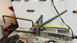
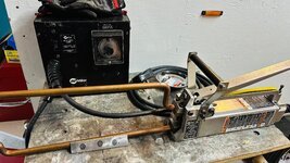
Its a Miller LSMW-52-T. 220 V with a timer. I installed a new outlet and it did work reasonably well. I did get some decent welds.

But I noticed it was working erratically. A little investigation uncovered some twisted and damaged wires.

Okay, so the SJ cord is 16GA 4 conductor. So I thought it would be worth it to just replace the cord. I purchased 14GA wire because you know more bigger - more better. Now it doesn't work at all. The contactor closes and I can hear it hum but there is apparently zero current now passing through the welder tips.

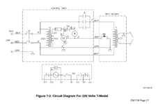
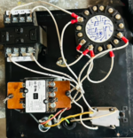
I have the schematics, took detailed pictures before I took it apart and I am sure I wired it back up correctly. I disconnected the primary wires across the welder and I get continuity and around 60 ohms. I checked the output side of the welder and I also get continuity and around 2 ohms.

I am kind of at the end of ability to troubleshoot this thing. I'm not sure what's wrong and why it wouldn't work at all.

Is anyone out there savy enough in such matters to help me out?

Much TIA,
Rick
 

Attachments

  • SpotWelder_6.jpg
    SpotWelder_6.jpg
    917.9 KB · Views: 51
  • SpotWelder_9.jpg
    SpotWelder_9.jpg
    528.9 KB · Views: 33
To avoid these ads, REGISTER NOW!
OP
R

RickP330

Well-known member
Joined
Apr 12, 2007
Messages
831
Location
Middle Island, NY
Here are some additional pictures of the set up.

The two primary wires and I made similar reconnections.
 

Attachments

  • SpotWelder_12.jpg
    SpotWelder_12.jpg
    996.1 KB · Views: 30
  • SpotWelder_7.jpg
    SpotWelder_7.jpg
    719.6 KB · Views: 29
  • SpotWelder_8.jpg
    SpotWelder_8.jpg
    731.9 KB · Views: 40
Last edited:
OP
R

RickP330

Well-known member
Joined
Apr 12, 2007
Messages
831
Location
Middle Island, NY
The schematic for the non timer model is below, and I thought maybe I could just hook it up like this for a test, but It's so simple I can't imagine this would work any better...
 

Attachments

  • Screen Shot 2024-12-07 at 2.51.58 PM.png
    Screen Shot 2024-12-07 at 2.51.58 PM.png
    45.4 KB · Views: 34

LXCam

ALLIANCE MEMBER
Joined
Apr 23, 2013
Messages
19,200
Location
AZ
Have you confirmed the relay is closing when you activate the time delay switch?. Also there's something interesting about that schematic. All three legs of the relay are shown wired in parallel. Since those carry all the current and with the welds being inconsistent I'd also suspect the contacts are burned up.
 

LXCam

ALLIANCE MEMBER
Joined
Apr 23, 2013
Messages
19,200
Location
AZ
The schematic for the non timer model is below, and I thought maybe I could just hook it up like this for a test, but It's so simple I can't imagine this would work any better...
You could do this if you had too. But having that timer working is the key to getting a consistent weld once you establish the setpoint.

One more thing, Have you confirmed fuse F1 isn't blown?.
 
OP
R

RickP330

Well-known member
Joined
Apr 12, 2007
Messages
831
Location
Middle Island, NY
Have you confirmed the relay is closing when you activate the time delay switch?. Also there's something interesting about that schematic. All three legs of the relay are shown wired in parallel. Since those carry all the current and with the welds being inconsistent I'd also suspect the contacts are burned up.
I do hear the contactor close. I guess I could mount the volt meter to it to ensure it is getting 220v across it though. The relay has a copper buss plate connecting all three legs....

Fuse is not blown.

The timer part appears to work well, I'm just not getting any current in the weld...
 

Attachments

  • Screen Shot 2024-12-07 at 3.04.31 PM.png
    Screen Shot 2024-12-07 at 3.04.31 PM.png
    372.8 KB · Views: 24
Last edited:

Jim greengo

Well-known member
Joined
Sep 3, 2018
Messages
7,415
Location
Behind my house
I've had a bottom of the harbor freight version for a few years.
I replaced it once under warrantee.
After they gave me the new 1 I actually read the instructions and figured out I wasn't using it right,haven't had any problems with the new 1 since I learned to use it the right way. Hahaha
 

LXCam

ALLIANCE MEMBER
Joined
Apr 23, 2013
Messages
19,200
Location
AZ
I do hear the contactor close. I guess I could mount the volt meter to it to ensure it is getting 220v across it though. The relay has a copper buss plate connecting all three legs....

Fuse is not blown.

The timer part appears to work well, I'm just not getting any current in the weld...
Damn look at that set up. What's funny is the size of the jumper buss, because the upper contacts of that relay are still going to be rated for whatever that relay is rated for (can't read it). Anyhow pull the two screws and take a look at the condition of them.

So past that make sure you have voltage to the input of the transformer and if you do, check the secondary side (output). So you should have ~220 input and probably 12V output (keep the welding contacts isolated from each other during this test - thick card board with work). IF you are seeing voltage output, I'd start looking at the wire leads to the contacts.

If you aren't seeing 220 input, check out the wiring going from S1 to both the input of the relay and from the transformer.
 
OP
R

RickP330

Well-known member
Joined
Apr 12, 2007
Messages
831
Location
Middle Island, NY
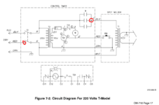
Does it make any sense I measure 113 VAC between these two points if S1 is open?

If I close the switch it reads zero.

If I break the black and white wires between the timer and the welder I have no continuity between ground and either end of the coil.

When the contactor closes there is 240 VAC across the welder coil.

RP
 

Attachments

  • Screen Shot 2024-12-07 at 4.51.06 PM.png
    Screen Shot 2024-12-07 at 4.51.06 PM.png
    113.4 KB · Views: 23
Last edited:

LXCam

ALLIANCE MEMBER
Joined
Apr 23, 2013
Messages
19,200
Location
AZ
Does it make any sense I measure 113 VAC between these two points if S1 is open?

If I close the switch it reads zero.

If I break the black and white wires between the timer and the welder I have no continuity between ground and either end of the coil.

When the contactor closes there is 240 VAC across the welder coil.

RP
Nope. I Pm'd you my number. This would be much easier talking you thru it.
 
To avoid these ads, REGISTER NOW!
OP
R

RickP330

Well-known member
Joined
Apr 12, 2007
Messages
831
Location
Middle Island, NY
Hold on, I did some exploratory disassembly. I was going to clean the electrodes. I do see some evidence of arching between the flexible braid and the upper electrode. I did have this apart while I was waiting for the cable. Perhaps something is amiss here?
RP
 

LXCam

ALLIANCE MEMBER
Joined
Apr 23, 2013
Messages
19,200
Location
AZ
Hold on, I did some exploratory disassembly. I was going to clean the electrodes. I do see some evidence of arching between the flexible braid and the upper electrode. I did have this apart while I was waiting for the cable. Perhaps something is amiss here?
RP
Possible except with S1 being a two pole switch you shouldn't have any voltage on the load side with it open. So something is skewed.
 

LXCam

ALLIANCE MEMBER
Joined
Apr 23, 2013
Messages
19,200
Location
AZ
Boy this would have been much easier with a call

Let me know what you find out
Spot Welder.jpg
 
OP
R

RickP330

Well-known member
Joined
Apr 12, 2007
Messages
831
Location
Middle Island, NY
Thank you LXCam, sorry about that. Most of what you are suggesting above does pan out. That 113 VAC when the switch is open is weird, but it is AC and through the transformer to the tongs is ground, so perhaps it's seeing that.

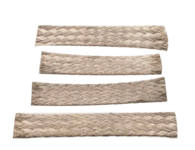
This braid does make sense though. I did have this apart and it has clearly been arching and was loose. I ordered new braids, let me replace them and see where we stand. Much Thanks
Rick

PS this is what it is supposed to look like. 4 layers of braids...
 

Attachments

  • SpotWelder_13.jpg
    SpotWelder_13.jpg
    1.2 MB · Views: 22
  • Screen Shot 2024-12-07 at 6.59.12 PM.png
    Screen Shot 2024-12-07 at 6.59.12 PM.png
    247 KB · Views: 30
Last edited:
OP
R

RickP330

Well-known member
Joined
Apr 12, 2007
Messages
831
Location
Middle Island, NY
Hi Guys,
Okay I have an update for this topic. I have the welder working now. It seems it was the braided connector on the top movable electrode. It had worked when I first unpacked it, but I guess I disturbed it while rebuilding it to the point where it became too high of a resistive joint. I replaced the braids with new ones and it welds really strong now, much better than even at first. Even get the initial sparks now as the current starts to flow.

So here is a summary:

I bought it from E-bay non returnable for $500.
It was working erratically and noticed the welder cable was broken so I replaced it with 4 conductor increasing the wire gauge from 16 to 14 - 24’ for $120.
Changed the plug to a 220V 20amp to 30amp plug to match it’s rating $35
It wasn’t working I suspected the switch, replaced for $35.
Noticed the braided connector was arching so I replaced it $60.

I also had to run and install a wall outlet from the box and dedicated two breakers for it. I had the wire $60

I did notice when I took it apart that the electrode winding (big copper U shaped bar) was too close to the housing, so I took it out and straightened it. When I did I noticed you could see the discoloring by the braided joint connection where it started overheating.

I’ll post some random pics.

So now I can claim success and I’ll move on to determining the proper settings for the metal gauges I plan on working on. Plus I want to experiment with welding through copper weld through primer and possibly some epoxies. I’ll vary weld time and tip diameter and clamping force to come up with a recipe. Thanks all for following and please let me know if you have any comments.
Rick
 
OP
R

RickP330

Well-known member
Joined
Apr 12, 2007
Messages
831
Location
Middle Island, NY
Okay success guys! Weld test coupon is in the foreground. I had the timer set at 2 seconds.

Also forgot to mention I made the brackets and a G-10 handle (I don't think that can be conductive) this thing is heavy and unwieldily.
 

Attachments

  • SpotWelder_14.jpg
    SpotWelder_14.jpg
    1,003.8 KB · Views: 26
OP
R

RickP330

Well-known member
Joined
Apr 12, 2007
Messages
831
Location
Middle Island, NY
The braided connector (it is 4 pieces clamped together) looking in very poor condition and it was not installed in the correctly. It should be installed as a U and it as installed in line. You can see the lower left totally broke in half.
 

Attachments

  • SpotWelder_16.jpg
    SpotWelder_16.jpg
    805.1 KB · Views: 18
OP
R

RickP330

Well-known member
Joined
Apr 12, 2007
Messages
831
Location
Middle Island, NY
Here is the secondary winding. If you look closely near the bolted connection you can see it was getting hot. Not so on the other side....
 

Attachments

  • SpotWelder_18.jpg
    SpotWelder_18.jpg
    1.1 MB · Views: 20
OP
R

RickP330

Well-known member
Joined
Apr 12, 2007
Messages
831
Location
Middle Island, NY
The spot welder is part of a larger project to upgrade my "welding department" LOL.
I started with my trusty old Mig welder. After 33 years of abuse it was time for some love. I replaced the front bezel my best friend broke when I lent it to him after the first year of use, it bothered me ever since! Cost some $80 but I had to do it. I also disassembled and sandblasted the cart. Put a coat of black singe stage urethane I had left over from another project.
Then it had so much overspray on it you couldn't read the stickers any longer. I wet sanded and compounded the paint, new wire reel and topped off the tank and tip supply while I was at it.

So I think the next step is to find a small used TIG welder to round out the complement.
RP
 

Attachments

  • Mig_Welder.jpg
    Mig_Welder.jpg
    1.4 MB · Views: 25
OP
R

RickP330

Well-known member
Joined
Apr 12, 2007
Messages
831
Location
Middle Island, NY
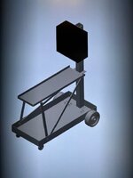
Hi all, since this thing panned out - I drew up a mobile cart for it so I can safely store and use it. I sent it out to a sheet metal shop and got a fairly reasonable quote. Hoping I can purchase the parts next month. Thanks for the help and I'll keep you posted!
RP
 

Attachments

  • WeldCart.jpg
    WeldCart.jpg
    38.8 KB · Views: 17
To avoid these ads, REGISTER NOW!
Top Bottom