longcreekridge
Member
- Joined
- Jul 31, 2024
- Messages
- 8
Hello. Main question is asked in my thread title. Here's some additional context (sorry to be long winded):
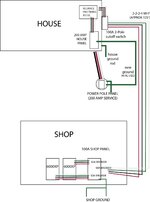
I look after an old farmhouse collectively owned by my wife's family. The kind where the (200A) electrical service is on a power pole outside, with a panel and a main breaker/disconnect that feeds another (sub) panel inside. Evidently the original install dates from a time, or was installed in an area (rural Central VA), when full size grounds were not always run. The external panel has neutral and ground bonded, as you would expect. The internal house panel is only fed by two hots and a neutral. The internal panel (an old ITE) also has its neutral and grounds bonded (see pic). I recently learned that this is incorrect, at least according to current code, and actually creates an unsafe situation. The situation is complexified and compounded by the fact that that I recently built a workshop near the house that is solar powered, and I am 99% complete with the process of tying that solar power into the house for both backup and load sharing (90A breaker on shop panel > 2-2-2-4 mobile home feeder > 100 amp external disconnect > Reliance A510C Transfer Switch > Internal Panel).
After explaining all this on a solar power forum, I was informed that I needed to rectify the situation by:
A) Running a full size ground from external panel to house panel
B) Lifting the ground/neutral bond in the house panel.
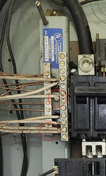
I've done A but need some help with B. I experimented a bit yesterday (with power off) and thought I had figured out where the bonding occurs. In the second pic, I've circled two areas. The top one is where I first thought the bonding occurs, but no dice. You can't see it, but the bottom circle highlights a screw that seems to tie the grounding bar into the built in panel ground that runs across to a symmetrical prong on the other side. However, even with all these screws backed out I was still getting continuity between the neutral and ground bars. What am I missing or getting wrong? Thank you kindly to anyone who can help.
I look after an old farmhouse collectively owned by my wife's family. The kind where the (200A) electrical service is on a power pole outside, with a panel and a main breaker/disconnect that feeds another (sub) panel inside. Evidently the original install dates from a time, or was installed in an area (rural Central VA), when full size grounds were not always run. The external panel has neutral and ground bonded, as you would expect. The internal house panel is only fed by two hots and a neutral. The internal panel (an old ITE) also has its neutral and grounds bonded (see pic). I recently learned that this is incorrect, at least according to current code, and actually creates an unsafe situation. The situation is complexified and compounded by the fact that that I recently built a workshop near the house that is solar powered, and I am 99% complete with the process of tying that solar power into the house for both backup and load sharing (90A breaker on shop panel > 2-2-2-4 mobile home feeder > 100 amp external disconnect > Reliance A510C Transfer Switch > Internal Panel).
After explaining all this on a solar power forum, I was informed that I needed to rectify the situation by:
A) Running a full size ground from external panel to house panel
B) Lifting the ground/neutral bond in the house panel.
I've done A but need some help with B. I experimented a bit yesterday (with power off) and thought I had figured out where the bonding occurs. In the second pic, I've circled two areas. The top one is where I first thought the bonding occurs, but no dice. You can't see it, but the bottom circle highlights a screw that seems to tie the grounding bar into the built in panel ground that runs across to a symmetrical prong on the other side. However, even with all these screws backed out I was still getting continuity between the neutral and ground bars. What am I missing or getting wrong? Thank you kindly to anyone who can help.