With my tools and material (.015R carbide insert on 1018 CF), I usually shoot for a .015-.020 finish cut per side. That means I want to rough it .090-.120 over, then start the 3 passes. Here's a screenshot with values from the last time I used it:

Good info
@zanyad and I think I may have come to the same conclusion at what you are saying. In the past I have gotten in trouble getting too close to finished tolerances and then end up overshooting my target when trying to take lighter cuts, plus the finish has to be "massaged" using a combination of files and progressively finer emery paper. From my experience, especially with carbides, the nose radius plays a large role in not only the final finish, but also what can and cannot be removed and still net acceptable results, although surface finish can be subjective.
I'll try to explain what I "think" is happening and you tell me if I'm off my rocker.
The noze radius of the tool being say .015" such as in the TCMT 21.51 or DCMT 21.51 inserts I'm using seem to "skim over" the surface when trying to take cuts down under that particular nose radius and therefore I would continue to creep in a few thou at a time until all of a sudden the nose radius gets under the surface and BAM! All of a sudden I overshoot and now I'm .010 or more undersize.

When I was playing and experimenting with not only the DRO, but also depth of cuts throughout this tool project I think I really stumbled across something in this matter. I'm sure this is not new news to anyone with more experience, but to me seeing this with my own eyes and trying different depths of cuts really drove it home in my head of what I think is taking place.
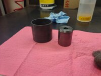
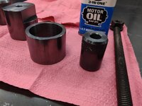
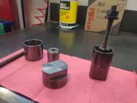
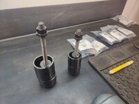
I was needing to remove a lot of material because the stock and tubing that I had on hand was not as close to what I needed so I found myself having to removed .300"-.400" or more from both the ID and the OD of the stock, which also gave me a great opportunity to test my theory and play with various depths of cut and take measurements along the way all while monitoring surface finish. I have also struggled with boring to a flat bottom hole, which I feel much better about now after completing this project. I feel very confident with actual turning speed and feeds as far as machine settings for both lathe and mill work, depending on material. I also have what I think is a pretty good feel for feed rates, the area I have struggled with is depth of cut and mainly on mild steel because it is so less forgiving when it comes to surface finishes.
Now my lathe is fairly sturdy but not what I would call as rock solid as say some of the older machines having more mass and weighing 2k-3K plus pounds. The new lathe stand did help mine in the rigidity department, but it is still a relatively light machine, so I am not able to take .125" plus depth of cuts with my 2HP lathe.
When I was starting my cuts, I would start out heavy (for my machine) at around .060"-.080" depth of cuts. I have my DRO set to read total diameter so that is .030"-.040" depth of cut per side and I was getting a very nice finish and the chips were coming off straw colored to maybe very pale light blue so although I was pushing my limits, I felt like it was a good rate of removal to net me both the speed as well as finish.
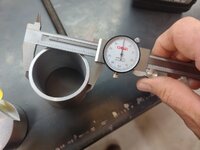
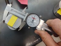
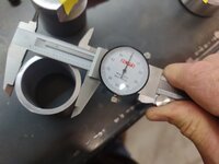
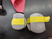
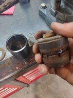
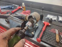
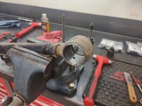
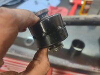
When I took closer to .025"-.030" total material removal, even though the chips were coming off nice the surface finish suffered greatly. I went back to taking .080" total removal and throughout the measuring I was pretty much dead nuts on the sizing of the part as it was being turned down. I saved .045"-.050" for the finish cut and the results were amazing as you can see above by the surface finished. What I also learned was that I no longer had to fear of overshooting and could repeat my results time and time again by using this process and the final dimensions were spot on dead nuts on my target, right to the thousandth. This was kind of the "a ha" project for me.
On a side note, I'm not sure how everyone else turns to sizes, but prior to having the DRO and solely using the dials, I would measure after a test cut, then subtract my target to see how much material I needed to remove. When I got down to under .200" (one turn of the dial), I would offset my dials so that my final measurement would land me at zero on the dial. Not sure why I did that vs. zeroing and then turning to a specific measurement other than a coworker taught me that many years ago and it just kind of stuck with me. I think I liked that process because if I set the dial so I would land on zero when at my target, if I got distracted or got called away to the phone or something, I wouldn't have to remember the target as it was already set for zero on the dial, then I would divide that up into about three final passes but seemed to always get fearful when nearing my target and back off the depths of cuts, which therefore led me to poor surface finishes and overshooting my target as mentioned above.
When I installed the DRO I kept forgetting to program my target into the DRO and would merely zero the scale I was using. Well, I finally decided to figure out how to offset the DRO to count down to zero so I could measure a part and if needing to remove more than the one rotation of the dial, .200", then I learned how to just punch the offset into my DRO and then leave a final pass of that .045"-.050" and the results were both great surface finish as well as landing exactly on my target dimension.
Sorry, for the long overview, but this was the first real project where I pushed myself to actually learn the functionality of the DRO in the respect of offsetting my dimensions so I land at zero for my final pass as well as pushed myself to better understand the relationship between the insert and surface finish and seeing as how I was using mild steel, this seemed to be the perfect learning opportunity as mild steel seems to be the hardest material I have come across thus far to obtain a nice surface finish, although that can be somewhat subjective.










 trammed is the biggest factor. ( Putting in new spindle bearings also made a massive difference )