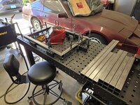
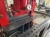
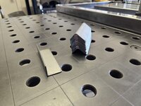
I don’t really know anything about your cutting
No one should expect anyone else to! It's how I view most things in that, anytime I bring up a new topic about something, I share enough that will either generate interest, or just not make someone feel dumb for not knowing what I'm talking about.
but
I thought You need - In cut & Out cut?
I find it really simple to look at something in 2D, and visualize what will remain and what will fall out.
Something I learned some years ago is that there are people in this world that don't have an 'inner voice'. That means that a person can't think or read something and imagine their own voice speaking in their head. This is where sometimes you find people speak out loud too or something like that.
The same goes for visualizing things.
If you've ever played the latest Mario Party, or any brain teasers, you may have seen those 3D puzzles that are missing a piece and you need to know visualize which way your 'separate' piece needs to rotate to match the example shown. That or choosing the correct piece of out many.
does your cutting just blow through your thinner materials
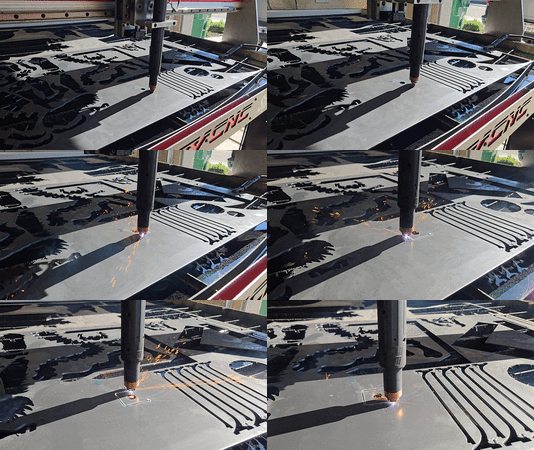
Plasma just consists of a high volume of air and electricity to create a cutting flame to cut through steel.
Important part is that a circuit must be completed for that arc to generate - a work clamp is attached to the metal you're cutting, and the torch (where the flame is emitted) is the other end of that circuit. As long as there's metal underneath, you have a completed circuit.
The thicker the material, the more current you need!
At 45 amps my setup I think maxes out at 1/2" or 3/4". I've only cut as thick as 3/8" in both aluminum and steel.
can you give the Class a small tutor on your cutter - How does it all work ?
thank you in advance
Well, hope all the information above covers the majority of it!
Everything I described was just on the plasma end.
Getting into CNC by itself is really just knowing CAD and CAM.
In short, CAD (computer aided design) is the drawing or designing of whatever you're trying to create. Where I have the most fun is when someone comes to me and asks "hey, can you make this?" or "I have an idea, can you make this happen?"
Unfortunately, the majority of CNC actually stems from the CAD part of the process in that you are using a computer to draw whatever it is you need to design. Many people give up right away as they can never get passed this step.
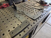
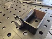
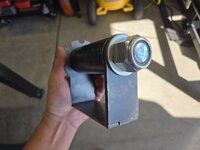
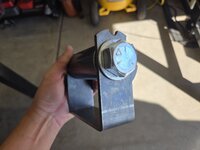
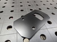
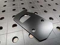
A most recent example is the part above with the large bolt. But let's go back to an earlier project here.
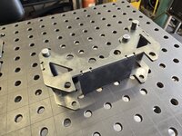
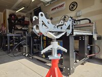
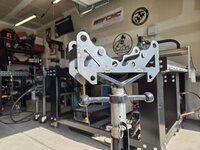
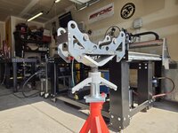
My friend, who works in HVAC, told me about these assemblies that sit on top of a pipe jack. Apparently they allow one to run a bolt (with bearings on each end) to allow the end user to easily and safely rotate pipes of various sizes to mate up with a flange.
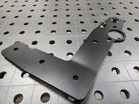
Never having made one, I looked online at one and came up with this.

Now, the version I found online had but two crappy images so I had to simply visualize what I need it to do, and how to make it happen.
In the screenshot above I made a number of circles in different diameters, simulating the various pipe sizes found. I also played with spacing of the bolt holes to allow the assembly to clear any pipe size when other holes are not in use.
After I drew that, then came the means of sitting it on the pipe jack itself.
The whole thing was really easy actually and took no more than an hour to design, cut, and well make it a real thing.

I'm also a welder and fabricator, which means I'm not only welding/repairing/making stuff but also designing stuff as I go.
Anyway, so that explains the design portion of it.
Next up comes CAM (computer aided manufacturing) and this is the other part that many find difficult.
Now that we have our design (a vector file), we need to convert this image into a bunch of commands for our table to follow. As much as many of us would like to simply hit a button and just go, there are many rules and parameters that need to be adjusted in order to achieve the best cut possible.
If you cut material too fast, you can get really bad beveling. If you cut too slow, you risk fusing your metal after being cut. This is just summarizing the two really as various speeds can also attribute to "dirty" cuts with dross sticking to the backside of the material and more.
Then you've got "piercing" which many don't even account for.
Take something like this for example. The green arrows there are an example of a pierce point, and while it may look rather big compared to the cut line itself, is actually as small as you can get it. But if you also look at the purple arrow, that is also evidence of a small pierce (and lead in).

The part is much smaller than it looks but many people struggle with the appropriate settings for making these things as hidden as possible. Another one of my examples.

There are times where pierce points are not only really big, but they also have such short lead ins that actually disrupt the cut path it's on as well.
Often times you will never notice it as many items get painted, but anyone that's into CNC will look for these things in their own work along with others.
Then there's also the importance of having your table completely dialed in. This means your table was assembled absolutely square, your gantry is perpendicular to your cutting material, your Z-axis is trammed precisely, and your movement is fluid in every direction.
Pair all that with what I mentioned above about cut speeds, and you still need to ensure you have the proper amp setting on your plasma cutter, as well as air as dry as possible.
This is because the number one killer of anything plasma-related is moisture and any moisture in your air will quickly destroy consumables (and affect cut quality by a large margin).
I'm deviating a bit because I got to talking about air and other stuff.
We didn't even cover rules but in short it means, a change of cut settings to achieve the best quality possible in any given situation.
Below is a great example of that.

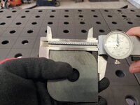
I created this piece as my own test cut piece. I use it for everyone I teach CNC to and use it myself when I've dialed in tables.
It is a simple 5/8" hole, in a 2.5" x 2.5" square with a radius at two corners from 3/16" steel.
If cut speeds are too fast on your outside cut, it is possible to experience severe beveling especially on the radius corners. Too fast of a cut in the center will also lead to massive tapering. Having a table that isn't square will mean a square that doesn't measure evenly along both sides. All of that beveling will also mean that your part cut will not be true to size.
But there's one more thing I didn't mention! You also have cut height and pierce height to be set correctly.
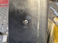
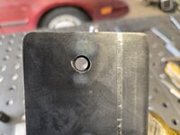
You'll notice just how tiny the lead in mark is on that square cut out, as well as how true to size the overall dimensions are. This is because every part of everything I mentioned was right on point.
The center hole?

It measured at 0.628", just a hair over the 0.625" desired hole size we programmed. This is about as close as you'll get with plasma based on the nature of how it cuts.
So yeah, there's a lot to it but I'm going on now 3 years doing this and it's been fun as hell.
Completely self-taught too!
If this was long and boring, I apologize

If you found it to be helpful and informative, just let me know below!