To avoid these ads, REGISTER NOW!

Quincy 325 Rebuild Questions

happymachinist

Well-known member
Joined
Jul 2, 2015
Messages
118
Location
Central NE
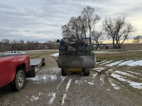
As the title states, I am hoping to use this thread to post questions I have for my recently acquired Quincy 325 air compressor.

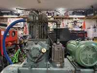
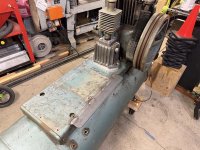
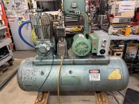
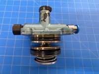
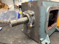
The pump is a ROC 13. I recently swapped motors (old motor was 3 phase) It builds 20PSI of oil pressure per the OEM gauge and does not seem to have a knock.

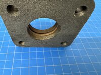
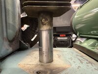
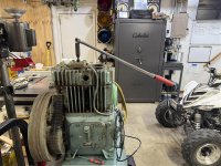
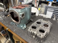
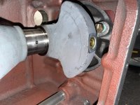
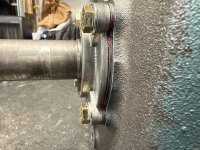
It does, however, have a bad leak between the pipe and the 4 bolt flange on top of the cast iron piece I am pointing to. I guess I would call it an intercooler?

How does one separate the casting from the pipe? I am trying not to pull the head but will if I have to. Is there a seal under the flange?

Reason for not wanting to take the head off is so I can further diagnose the overall condition of the pump to help me decide what rebuild kit I need to order.

Thanks, Everyone.
 

Attachments

  • intercooler.jpg
    intercooler.jpg
    289 KB · Views: 128
To avoid these ads, REGISTER NOW!

PirateTurner

Well-known member
Joined
Dec 28, 2020
Messages
182
Location
Trenton SC
I take it you are not willing to cut the pipe? If not can you remove the piece your pointing to and work upwards from there?
 
OP
H

happymachinist

Well-known member
Joined
Jul 2, 2015
Messages
118
Location
Central NE
So this is what it entailed. Sorry if my post sounded lazy, I just didn’t know what (if anything) was on the end of the vertical pipe. For diagnostic reasons I didn’t want to disturb the head at this time.

I removed the 4 bolts on the flange persuaded it up then rotated the pipe enough to slide the intercooler off.

In the flange is is a good sized o-ring to do the sealing. The problem is the pitted up pipe. I can either fabricate a spacer to move the whole thing up to a fresh portion of pipe or machine a new top plate with a 3/4 npt port and run copper and compression fittings.

Thanks guys for the help. Hopefully this will help someone else down the road.
 

Attachments

  • IMG_3519.jpeg
    IMG_3519.jpeg
    898.6 KB · Views: 93
  • IMG_3525.jpeg
    IMG_3525.jpeg
    683.7 KB · Views: 69
  • IMG_3526.jpeg
    IMG_3526.jpeg
    908.9 KB · Views: 65
  • IMG_3529.jpeg
    IMG_3529.jpeg
    646.8 KB · Views: 70

PirateTurner

Well-known member
Joined
Dec 28, 2020
Messages
182
Location
Trenton SC
I'd consider being lazy, clean the pitted area and "rebuild" it with a heat tolerant epoxy filler of some sort, sand it smooth and give it try. But, I'm no millwright.

Please keep us updated. I really enjoy a good 325 story. Particularly when the ROC is less than 100.
 
OP
H

happymachinist

Well-known member
Joined
Jul 2, 2015
Messages
118
Location
Central NE
Well we’ll see how this works long term. I cleaned everything up and fabricated a 3/4” thick aluminum spacer to move the seal point up by the same 3/4”. This puts the o-ring on a fresh chunk of shined up pipe.

Flat sanded gasket surfaces, new o-ring, new hand cut gasket and bolts.

I tried first without the RTV but it would not seal without. Not going to be fun when I have to disassemble.

Now I need to starts on a finalized motor mount. As cool as the cast iron Quincy mounts are they are not fun to adjust.
 

Attachments

  • IMG_3551.jpeg
    IMG_3551.jpeg
    900.7 KB · Views: 55
  • IMG_3552.jpeg
    IMG_3552.jpeg
    770.3 KB · Views: 54
  • IMG_3550.jpeg
    IMG_3550.jpeg
    663.9 KB · Views: 50
  • IMG_3549.jpeg
    IMG_3549.jpeg
    1.1 MB · Views: 53
OP
H

happymachinist

Well-known member
Joined
Jul 2, 2015
Messages
118
Location
Central NE
With the cast iron pulsation damper sealed up I have been able to dig into the compressor a little more. I went ahead and added a motor tensioner bracket to the tank top plate. As mentioned before, I like the looks of the old cast iron motor mounts, but they **** to get things tensioned and straight. Adding the tensioner required me to weld on a piece of flat stock to the tank top plate. I also added my an hour meter and a keyed switch to prevent unauthorized use. The original oil pressure gauge was also flaky, so I have added a new 0-30 psi liquid filled gauge.
 

Attachments

  • 9444144f-9cf4-4eaf-b517-68dc054b19e8.jpg
    9444144f-9cf4-4eaf-b517-68dc054b19e8.jpg
    94 KB · Views: 44
  • 3a36e768-afc1-4579-9945-4848765493ae.jpg
    3a36e768-afc1-4579-9945-4848765493ae.jpg
    111.7 KB · Views: 44
  • d72ca814-27b2-4793-a8ab-a26cf3da6915.jpg
    d72ca814-27b2-4793-a8ab-a26cf3da6915.jpg
    113.4 KB · Views: 48
OP
H

happymachinist

Well-known member
Joined
Jul 2, 2015
Messages
118
Location
Central NE
After some more investigations it appeared that the unloader tower on top of the head was not functioning properly. I would run the compressor pump (not hooked to the tank) and apply air from my little compressor to the hydraulic unloader valve (brass valve on the side) and whether I applied air to the brass valve or not the compressor would pump (unloader not working).

I took the hydraulic unloader valve out of the equation and applied air to the tower directly with some air tubing and it was the same as before. With or without air to the tower the compressor would pump air.

I sucked at taking pictures during disassembly since my hands were a bit nasty and these fasteners were TIGHT!!!. Long story short the unloader pin (PN 6965) was seized in the spacer (PN 6964) This would not allow the platform to push on the unloader pins. Both components are heavily corroded.

So needless to say, looks like I am rebuilding the head. After I tore in to it...it's probably best. This air compressor came from a little town co-op. I thought that would be good since I wouldn't expect it to have too many hours on it for an air compressor of this quality. All indications are that I am the first one inside it since manufacture. It appears that it might have ran in short bursts...not long enough to get up to temp and burn off the condensation.
 

Attachments

  • 1a6cef86-1542-4f22-be85-7060025d28f0.jpg
    1a6cef86-1542-4f22-be85-7060025d28f0.jpg
    106.4 KB · Views: 38
  • 48a2bd7f-712e-4c90-b47d-d03da43dc052.jpg
    48a2bd7f-712e-4c90-b47d-d03da43dc052.jpg
    96 KB · Views: 37
  • 646005c8-6fac-41ac-9f62-0d77c7fe465c.jpg
    646005c8-6fac-41ac-9f62-0d77c7fe465c.jpg
    85.4 KB · Views: 36
  • abe24b99-3d19-42fc-adbb-c91bc60e62c3.jpg
    abe24b99-3d19-42fc-adbb-c91bc60e62c3.jpg
    121 KB · Views: 39
  • 2731c394-6a7a-47ad-9a08-a10bbb09d912.jpg
    2731c394-6a7a-47ad-9a08-a10bbb09d912.jpg
    93.2 KB · Views: 38
  • b795636f-ff77-4ccb-ae18-622949ac949e.jpg
    b795636f-ff77-4ccb-ae18-622949ac949e.jpg
    93 KB · Views: 39
OP
H

happymachinist

Well-known member
Joined
Jul 2, 2015
Messages
118
Location
Central NE
I don’t think mentioned it but I have been thinking about how nice it would be to have dual control on this air compressor.

The main reason for getting this air compressor is for sand blasting parts prior to powder coating so a continuous run option makes a lot of sense for my situation.

After pricing the components to add an extra unloaded tower to the LP cylinder to make it an LVD I stumbled across this “beaut” on marketplace in working but not working well condition. I’m in it for the same price of new LVD components so if that’s all I get out of the two heads I guess it’s a wash.

For those new to the 325 (like me) the last picture is a disassembled unloader tower.

Now I’m considering a dual pump for the rare occasion that I break out the pot blaster…
 

Attachments

  • IMG_3761.jpeg
    IMG_3761.jpeg
    1.3 MB · Views: 41
  • IMG_3762.jpeg
    IMG_3762.jpeg
    1.3 MB · Views: 37
  • IMG_3754.jpeg
    IMG_3754.jpeg
    1.7 MB · Views: 46
OP
H

happymachinist

Well-known member
Joined
Jul 2, 2015
Messages
118
Location
Central NE
This weekend was fairly productive, To cut to the chase, I saw/heard/felt some things that led me to dig deeper than I wanted but it was good that I did. The HP rod crank pin bushing is ROACHED! The roaching of this bushing seems to have lead to an also roached wrist pin bushing. Quick caliper measurements put me at .0100" clearance on the wrist pine when spec is .0004-.0009" IIRC. I didn't measure the rod/crank pin bushing...I'll let the pictures tell that story.

So this brings me to my next question: Who all has modified the orifices or spill valve? I just got done ordering parts from Pacific Air Compressors and the very helpful gentleman did not advise any modifications. I understand his advice, I don't think I'm smarter than the engineers at Quincy were in 197X but it does seem to be somewhat documented that these older ROC pumps lack the needed oil in locations furthest from the oil pump.

Any insight is appreciated. I am still searching the forums and YouTube to understand what others have done and how it worked. This pump made it 50 years as designed I'd be happy if I get 40 out of this rebuild. :ROFLMAO:

I'll post pictures when I can, thanks everyone.
 
OP
H

happymachinist

Well-known member
Joined
Jul 2, 2015
Messages
118
Location
Central NE
Here are some disassembly pictures. There was some black sludge at the bottom of the crank case that is expected from non detergent oil, but not a ton.

The screen was pretty clean which was encouraging.

The rod bearing pictured is the high pressure cylinder. As I mentioned the wrist pin bushing is about .010” oversized.

Parts have arrived from PAC. After talking to them they mentioned the new wrist pin bearing will come undersized, so I need to design a fixture so I can bore it out after pressing it in the rod.

Last picture is where my oil pressure adjustment screw was at to get 18psi of oil pressure. I want to document before and after all new bearings.
 

Attachments

  • IMG_4166.jpeg
    IMG_4166.jpeg
    673 KB · Views: 38
  • IMG_3987.jpeg
    IMG_3987.jpeg
    838.2 KB · Views: 33
  • IMG_3989.jpeg
    IMG_3989.jpeg
    638.5 KB · Views: 31
  • IMG_3988.jpeg
    IMG_3988.jpeg
    905.4 KB · Views: 32

W-Cummins

Well-known member
Joined
Jan 9, 2006
Messages
1,641
Location
Iowa
The big end of mine was not damaged but the small end was just slightly worn!
rod01-jpg.19338
 
To avoid these ads, REGISTER NOW!
OP
H

happymachinist

Well-known member
Joined
Jul 2, 2015
Messages
118
Location
Central NE
The big end of mine was not damaged but the small end was just slightly worn!
rod01-jpg.19338
What model or ROC do you have? My new bushing looks as thick (per side) as yours looks in this picture. New it would have been much thicker per the gap on top of the wrist pin.

I’m trying to work through getting the high pressure rod and wrist pin bearings more oil. I’ve got some ideas…some are good…others questionable 🤣
 

W-Cummins

Well-known member
Joined
Jan 9, 2006
Messages
1,641
Location
Iowa
It's the big brother of yours, a model 390. I "think" it was roc 14 if I remember correctly, if it matters I will look at the tag for you. I replaced the bushing, and had the machine shop hone it to around 7 tenths clearance. I also replaced the pin and the piston.

I think there is a slight problem with these pumps and this "defect" but I don't think it's worth worrying about it, I know that mine will out last me and my children before it becomes a problem again!

I guess you could increase the chamfer at the top of the rod, and maybe enlarge the hole (in both the rod and the bushing) slightly. This probably won't reduce the strength of the rod much as it wears on the bottom of the bore.
 
OP
H

happymachinist

Well-known member
Joined
Jul 2, 2015
Messages
118
Location
Central NE
Thanks for the clarification. Exact ROC isn’t needed. I have thought similar things about the rod. I’d also like to see the oil slot in the rod/crank bearing lengthened so that the rod sees oil pressure for a longer duration. (This would only help the wrist pin bearing)

I’m with you on the point of if I rebuild with a plug in place of the spill valve it will outlast me for sure…

My lingering thought though is I’ve seen guys online that have rebuilt compressors with plugs and they seem to have the same failure all be it after (probably) thousands of hours of use
 
OP
H

happymachinist

Well-known member
Joined
Jul 2, 2015
Messages
118
Location
Central NE
A little more cleaning, inspection and A LOT of flat “lapping” on the ol rock.

Both cylinders are in good shape. High pressure is nearly “perfect.” Low pressure cylinder is within .001” of being round and straight (no step) so I’ll most likely just knock the glaze off with a flex hone to help seat the new rings.

I have cherry picked the best valve bodies/bumpers and lapped them also to 600 grit.

Things that are ready for assembly have been bagged to keep them clean.
 

Attachments

  • IMG_4213.jpeg
    IMG_4213.jpeg
    854.1 KB · Views: 24
  • IMG_4127.jpeg
    IMG_4127.jpeg
    739.9 KB · Views: 22
  • IMG_4153.jpeg
    IMG_4153.jpeg
    1 MB · Views: 20
  • IMG_4130.jpeg
    IMG_4130.jpeg
    1,003.7 KB · Views: 19
  • IMG_4099.jpeg
    IMG_4099.jpeg
    751.1 KB · Views: 19
  • IMG_3994.jpeg
    IMG_3994.jpeg
    1.2 MB · Views: 18
  • IMG_3992.jpeg
    IMG_3992.jpeg
    679.7 KB · Views: 17
OP
H

happymachinist

Well-known member
Joined
Jul 2, 2015
Messages
118
Location
Central NE
I was able to rig up a fixture to ream and lap the high pressure wrist pin bushing. Spec is .0004”-.0009” clearance. I ended up at about .0008”

I was also able to strip and rebuild the hydraulic unloaded valve. The small brass component in my hand is what I think failed. I could hear a small hiss of air leaking when air was supplied to the “R” side of the circuit.

I hit the polished brass with a quick coat of clear to help it stay shiny.
 

Attachments

  • IMG_4237.jpeg
    IMG_4237.jpeg
    526.5 KB · Views: 16
  • IMG_4236.jpeg
    IMG_4236.jpeg
    443 KB · Views: 14
  • IMG_4235.jpeg
    IMG_4235.jpeg
    411.8 KB · Views: 13
  • IMG_4220.jpeg
    IMG_4220.jpeg
    669.6 KB · Views: 14
  • IMG_4214.jpeg
    IMG_4214.jpeg
    431.8 KB · Views: 16
  • IMG_4197.jpeg
    IMG_4197.jpeg
    696.4 KB · Views: 20
OP
H

happymachinist

Well-known member
Joined
Jul 2, 2015
Messages
118
Location
Central NE
1770748128102.png
So I am getting close enough that I would like to get parts ordered for dual control.

This 3 way check valve is what ROTARYCOMPTECH used in his video years ago. Does anyone have a part number or know where to get something equivalent?

If not this part maybe someone can help me understand how Quincy would have done it from the factory. (He makes a comment that his way is a little different.)

To me without a check valve when switching over to continuous run the air would bleed out through the hydraulic unloader.
 

MacMcMacmac

Well-known member
Joined
Oct 21, 2014
Messages
1,585
Location
canada
You need a shuttle valve that automatically chooses between two inputs and sends the high signal to the unloader.


I remember the first 325s I worked on coming in from the oilfield set up like this. I seem to recall the shuttle valve had to be set up so the port supplied by the hydraulic unloader valve was on top so that the check ball would fall away from its port to ensure it operated properly. This might explain the orientation of the shuttle valve in the video. This was 30 years ago now, so I might be mistaken. They used air brake unloaders for control. It was what was handy and familiar I guess. Worked well though.

As you probably know, you have to set your pneumatic controller lower than the cut out pressure of your pressure switch or else it will continue to run stop/start. You also need an isolation valve to take the pneumatic controller offline to resume start/stop operation.

Shuttle-valve-4-2048.jpg
 
Last edited:

larry4406

Well-known member
Joined
Jan 27, 2006
Messages
19,330
Location
Northern Virginia
Not sure if this is helpful, but here is the “dual control” valve on my Puma TUE7580.

The small black lever (normally up) allows the unit to cycle per the pressure switch. When the lever is horizontal, continuous run is enabled.

I think I have more information on it on my desk top. Let me know if you want me to look.

IMG_3934.jpegIMG_3935.jpeg
 
OP
H

happymachinist

Well-known member
Joined
Jul 2, 2015
Messages
118
Location
Central NE
You need a shuttle valve that automatically chooses between two inputs and sends the high signal to the unloader.


I remember the first 325s I worked on coming in from the oilfield set up like this. I seem to recall the shuttle valve had to be set up so the port supplied by the hydraulic unloader valve was on top so that the check ball would fall away from its port to ensure it operated properly. This might explain the orientation of the shuttle valve in the video. This was 30 years ago now, so I might be mistaken. They used air brake unloaders for control. It was what was handy and familiar I guess. Worked well though.

As you probably know, you have to set your pneumatic controller lower than the cut out pressure of your pressure switch or else it will continue to run stop/start. You also need an isolation valve to take the pneumatic controller offline to resume start/stop operation.

Shuttle-valve-4-2048.jpg
Thank you, this is the EXACT info I have been looking for!! Knowing the correct nomenclature makes all the difference in a guy's google search.

I'll do some more research but if I had to order today I'd get this one from McMaster to match the other brass tid-bits.

Thanks again!!
1770937159522.png
 
OP
H

happymachinist

Well-known member
Joined
Jul 2, 2015
Messages
118
Location
Central NE
Not sure if this is helpful, but here is the “dual control” valve on my Puma TUE7580.

The small black lever (normally up) allows the unit to cycle per the pressure switch. When the lever is horizontal, continuous run is enabled.

I think I have more information on it on my desk top. Let me know if you want me to look.

IMG_3934.jpegIMG_3935.jpeg
Your picture is part of the equation...but I think I also need the shuttle/diverter valve Mac referenced to work with the hydraulic unloader. The hydraulic unloader doesn't allow the compressor to build pressure until the unit has oil pressure.

I do like how yours is tied into a multi-port pressure switch, though that could be handy for other applications.

1770937845675.png
 
OP
H

happymachinist

Well-known member
Joined
Jul 2, 2015
Messages
118
Location
Central NE
Little more progress. Reassembled the oil pump/bearing carrier and set the end play. There were approximately 7 steel shims of varying thicknesses and 7 plastic shims/gaskets right at .007”

I didn’t pay attention to the order they came out but when I reinstalled them I alternated plastic/steel and sprayed the plastic with Permatex high tack. (Not going to be fun to disassemble) It took a few times to get the end play right but I finally settled when I got to .0018ish

I opted for a plug in place of the spill valve after confirming the orifice for the far bearing is .032” on models that come with a plug or spill valve.
 

Attachments

  • IMG_4312.jpeg
    IMG_4312.jpeg
    547.4 KB · Views: 9
  • IMG_4308.jpeg
    IMG_4308.jpeg
    810 KB · Views: 8
  • IMG_4305.jpeg
    IMG_4305.jpeg
    855.5 KB · Views: 8
  • IMG_4301.jpeg
    IMG_4301.jpeg
    903.1 KB · Views: 9
  • IMG_4304.jpeg
    IMG_4304.jpeg
    686.2 KB · Views: 8
  • IMG_4295.jpeg
    IMG_4295.jpeg
    701.1 KB · Views: 9
Last edited:

PirateTurner

Well-known member
Joined
Dec 28, 2020
Messages
182
Location
Trenton SC
From the IPB ROC -011. Quincy term is Pilot Valve. You can search on eBay for Quincy Pilot Valve, etc.

1771113865532.png

1771113979011.png


1771114040275.png
 

Attachments

  • 1771113929171.png
    1771113929171.png
    749.7 KB · Views: 9
To avoid these ads, REGISTER NOW!
Top Bottom