To avoid these ads, REGISTER NOW!

Gas valve on furnace isn’t getting voltage - replace control board?

Hakeem

Well-known member
Joined
Jan 22, 2024
Messages
1,278
Location
Chicago
Woke up today to the furnace not working. The inducer motor spools up fine and the igniter glows but the gas valve never seems to open (no audible “click”). I checked the voltage across the wires to the valve and it’s not getting any power. The control board isn’t flashing any error signs, nor does there appear to be any sign of corrosion or damage (unlikely I know but i wanted to check anyways). My questions are as follows:

1) YouTube is telling me that this is a bad control board and needs to be replaced. I’m happy to do it but just want some confirmation from the folks here that the control board is most likely the issue, rather than load up the parts cannon and pray.

2) Googling the model number turns up a few options on Amazon. I’d rather get something like this with fast shipping and easy returns than roll the dice with something used from EBay. Is this a reasonable approach?


Attachments

  • IMG_1584.jpeg
    IMG_1584.jpeg
    758.2 KB · Views: 58
To avoid these ads, REGISTER NOW!

fitter30

Well-known member
Joined
Jun 23, 2019
Messages
2,992
Location
Peace Valley,mo
There's one or two hi limits a roll out switch by the burners. Need the complete model number to see if i can find a manual or at least a wiring diagram. Yours should be on the inside of blower door. Does this furnace have a inducer motor? Lennox doesn't publish much except for their dealers.
 

PCustoms

Well-known member
Joined
Jul 23, 2011
Messages
23,435
Location
VT
Check all switches and safeties, there should be at least 1 vacuum switch in the circuit.
 

PoorUB

Well-known member
Joined
Mar 29, 2021
Messages
11,705
Location
Fargo, ND
I'm thinking board. If it was a limit, it should not even attempt to fire up. The igniter lights, so I'm assuming it isn't a tripped limit.

On the other hand some furnaces have limits in the wire that runs between the board to the valve.
 

PCustoms

Well-known member
Joined
Jul 23, 2011
Messages
23,435
Location
VT
I'm thinking board. If it was a limit, it should not even attempt to fire up. The igniter lights, so I'm assuming it isn't a tripped limit.


Several years ago mine started acting up, same deal, ignitors were ready to go and no gas. Started looking around and figured out that the "squirrel guard" on the new PVC exhaust was iced over...cut it off and I was back in business
 

Bert_

Well-known member
Joined
Dec 24, 2016
Messages
9,775
Location
NW Iowa
Some furnaces have a second pressure switch directly in series with the gas valve. Some may have a limit switch there also.

If you have a switch like this in series with the valve, the control board doesn't have a clue what's happening with that particular switch.

Most of the safeties run back to the circuit board so you will get a code if they detect a failure.
 
OP
H

Hakeem

Well-known member
Joined
Jan 22, 2024
Messages
1,278
Location
Chicago
There's one or two hi limits a roll out switch by the burners. Need the complete model number to see if i can find a manual or at least a wiring diagram. Yours should be on the inside of blower door. Does this furnace have a inducer motor? Lennox doesn't publish much except for their dealers.

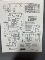
Ok here’s the wiring diagram on the inside of my door:
IMG_1586.jpeg

Check all switches and safeties, there should be at least 1 vacuum switch in the circuit.

Ok I do see the vacuum switch, how do I check it - see if it’s getting voltage? Check for continuity within the switch?

There’s no voltage coming from the board to the gas valve, it’s not just at the gas valve so there could be a safety switch somewhere that’s keeping the board from sending voltage.

Thanks for all the input :beer:
 

fitter30

Well-known member
Joined
Jun 23, 2019
Messages
2,992
Location
Peace Valley,mo
Diagram left side see burner both sides S47
Top left diagram S1 limit
Top right S18 air switch
Any closed switch will have zero volts vac across when closed
Open 24 vac
S18 will Lennox doesn't publish much except for their dealerslose only when fan is running. On the diaphragm should be a setting like .3" that's when it closes. Check line for blockage or cracked, stopped up at fan.
Air switch can't be bypassed till fan starts . 5 seconds later.
Wires will have to be traced to plug in on board P58.
 
Last edited:

PCustoms

Well-known member
Joined
Jul 23, 2011
Messages
23,435
Location
VT
Ok I do see the vacuum switch, how do I check it - see if it’s getting voltage? Check for continuity within the switch?

Check continuity across switch, but more importantly see if it changes state.

You'll need to check diagram to see if it is NC or NO, but it should change when conditions are met. Once you understand how it should work, you can "force" it (temporarily only!) to see if it fires
 

PoorUB

Well-known member
Joined
Mar 29, 2021
Messages
11,705
Location
Fargo, ND
On the right side of the diagram there is a K1 relay contact that needs to close to power the gas valve. What controls that K1 relay? I imagine something in the board that isn't shown.
 

PoorUB

Well-known member
Joined
Mar 29, 2021
Messages
11,705
Location
Fargo, ND
If you test for voltage from terminal 6 (yellow wire) to terminal 11 (brown wire) on the molex connector at the board it should read 24 volts , if not one or both of the S47 limits are tripped.

Then go from terminal 6 (yellow wire) to the 10 terminal (purple wire) on the molex connector and you should have 24 volt there with the inducer fan running. If not there is something wrong with the S18 pressure switch, or the S21 limit, or the S10 limit.

If you have voltage at terminal 6 to terminal 11 and terminal 10, replace the board.
 

Bert_

Well-known member
Joined
Dec 24, 2016
Messages
9,775
Location
NW Iowa
On the right side of the diagram there is a K1 relay contact that needs to close to power the gas valve. What controls that K1 relay? I imagine something in the board that isn't shown.

I would guess k1 is bad. I don't there is anything more than a timer between the ignitor and the gas valve.

The safeties are all satisfied because the board is attempting the ignition process by turning on the igniter.
 

fitter30

Well-known member
Joined
Jun 23, 2019
Messages
2,992
Location
Peace Valley,mo
I would guess k1 is bad. I don't there is anything more than a timer between the ignitor and the gas valve.

The safeties are all satisfied because the board is attempting the ignition process by turning on the igniter.
K1 controlled by the air switch
Post 10 has info on the switch and test it. Might be able to get on today at a appliance parts house with the same setting.
 

Bert_

Well-known member
Joined
Dec 24, 2016
Messages
9,775
Location
NW Iowa
K1 controlled by the air switch
Post 10 has info on the switch and test it. Might be able to get on today at a appliance parts house with the same setting.
I can't say for sure about this furnace, but most will not even turn on the ignitor without the correct signal from the pressure switch.

Some furnaces use a second pressure switch directly in series with the valve. This furnace does not show that.
 

fitter30

Well-known member
Joined
Jun 23, 2019
Messages
2,992
Location
Peace Valley,mo
I can't say for sure about this furnace, but most will not even turn on the ignitor without the correct signal from the pressure switch.

Some furnaces use a second pressure switch directly in series with the valve. This furnace does not show that.
Show just one switch. Switch can't have a closed contact before inducer turns on thats why have to wait a half second before bypassing. Post 9 right side diagram A 92 with the fuse. Terminal 10 feeds S18 air flow switch to power valve.
 

PoorUB

Well-known member
Joined
Mar 29, 2021
Messages
11,705
Location
Fargo, ND
K1 controlled by the air switch
Post 10 has info on the switch and test it. Might be able to get on today at a appliance parts house with the same setting.

No, the air switch feeds power to the K1 contacts, but something else controls the K1 relay. I looked the diagram all over and can not find the coil for the K1 relay. I guess it is buried in the board somewhere but they elected no to show it.

My guess is if there is power every where I mentioned the K1 relay is bad, or what ever controls it is bad.

Also, I jumper wire from terminal 10 to terminal 12 should fire the furnace. if all that is wrong is the K1 relay.
 

fitter30

Well-known member
Joined
Jun 23, 2019
Messages
2,992
Location
Peace Valley,mo
No, the air switch feeds power to the K1 contacts, but something else controls the K1 relay. I looked the diagram all over and can not find the coil for the K1 relay. I guess it is buried in the board somewhere but they elected no to show it.

My guess is if there is power every where I mentioned the K1 relay is bad, or what ever controls it is bad.

Also, I jumper wire from terminal 10 to terminal 12 should fire the furnace. if all that is wrong is the
A92 their split the diagram line ( right side of diagram)1 and low voltage. K1-3-4-5 showing thoses 4 contacts
Just wonder if the new board doesn't have the all the exact numbers of the old board. Like so many of these boards manufacturers might have the same board # except for the last revision #. Seen where a part comes from the manufacturer there might be a wiring change or a different board for compleate revision.
 
To avoid these ads, REGISTER NOW!

fitter30

Well-known member
Joined
Jun 23, 2019
Messages
2,992
Location
Peace Valley,mo
No, the air switch feeds power to the K1 contacts, but something else controls the K1 relay. I looked the diagram all over and can not find the coil for the K1 relay. I guess it is buried in the board somewhere but they elected no to show it.

My guess is if there is power every where I mentioned the K1 relay is bad, or what ever controls it is bad.

Also, I jumper wire from terminal 10 to terminal 12 should fire the furnace. if all that is wrong is the K1 relay.
A92 their split the diagram by line and low voltage. K1-3-4-5 showing thoses 4 contacts
Just wonder if the new board doesn't have the all the exact numbers of the old board. Like so many of these boards manufacturers might have the same board # except for the last revision #. Seen where a part comes from the manufacturer there might be a wiring change or a different board for compleate revision.
 

JohnX14

Well-known member
Joined
Jun 2, 2014
Messages
608
Location
Boston 'burbs
You might want to clean the flame sensor. Upi can clean them with a soft cloth and some alcohol. I just had a similar problem, and it was the flame sensor. My problem was intermittent, but similar. Everything worked but the gas valve wasn't opening. There were no codes.
 

allinon72

Well-known member
Joined
Jul 5, 2010
Messages
3,307
Location
Indianapolis
You might want to clean the flame sensor. Upi can clean them with a soft cloth and some alcohol. I just had a similar problem, and it was the flame sensor. My problem was intermittent, but similar. Everything worked but the gas valve wasn't opening. There were no codes.
It's hard to imagine a scenario where a faulty flame sensor wouldn't throw a fault code.
 

BurtEggley

Well-known member
Joined
Oct 8, 2024
Messages
888
hard to visualize anything that would not throw some kind of error. If the board thinks there is a call for heat, it should throw an error if heat / gas is not provided in time. I would unplug it for 10 minutes and plug it back it to see if it resets itself.

I'd also check S18, the 3amp fuse, and the 24V transformer. S18 has to close before the gas valve can work. It reads NO on the schematic, which usually means normally open. If it fails, which I had a brand new carrier unit with that problem, the gas valve won't come on because it can't verify that the inducer is running until S18 closes. It also looks like the ignitor is on the 120V side of the system so be sure that you actually have 24V present.
 

danski0224

Well-known member
Joined
Jan 29, 2005
Messages
13,520
Location
Near Naperville, IL
There should be an operation sequence flow chart and troubleshooting guide in the factory kneepads (installation manual).

Usually, if the sequence gets to the point where the igniter glows, all of the safeties are working.
 
OP
H

Hakeem

Well-known member
Joined
Jan 22, 2024
Messages
1,278
Location
Chicago
Ok, quick update - i swapped the board out with a new one as the family was complaining about the lack of heat and that seemed like the quickest fix. Issue was NOT resolved. Looks like I’ll be going through the whole list of testing you folks have generously provided.

I’m not super familiar with electronic troubleshooting. I’m getting 24v out of the transformer but not getting any power to the gas valve, so somewhere along that chain something has failed. My next steps will be to trace through the schematic with my meter to see which connection/switch/relay is failing to provide power to GV1 - is that about correct?

Am I looking for 24v at each step of the circuit?
 

PCustoms

Well-known member
Joined
Jul 23, 2011
Messages
23,435
Location
VT
Ok, quick update - i swapped the board out with a new one as the family was complaining about the lack of heat and that seemed like the quickest fix. Issue was NOT resolved. Looks like I’ll be going through the whole list of testing you folks have generously provided.

Why ask for advice, then ignore it and shotgun the board anyways?

You need to go through the steps that have been outlined above. IIRC post #10 was spot on
 
OP
H

Hakeem

Well-known member
Joined
Jan 22, 2024
Messages
1,278
Location
Chicago
Why ask for advice, then ignore it and shotgun the board anyways?

You need to go through the steps that have been outlined above. IIRC post #10 was spot on

You are not married I presume? “Happy spouse, happy house” is wisdom to live by.

I’m fine with no heat but the wife and baby were not, and so I just wanted to get the furnace back running ASAP.
 

PCustoms

Well-known member
Joined
Jul 23, 2011
Messages
23,435
Location
VT
You are not married I presume? “Happy spouse, happy house” is wisdom to live by.

I’m fine with no heat but the wife and baby were not, and so I just wanted to get the furnace back running ASAP.

Right, but your "fix" didn't fix anything...
 
OP
H

Hakeem

Well-known member
Joined
Jan 22, 2024
Messages
1,278
Location
Chicago
Right, but your "fix" didn't fix anything...

What can I say, after a long day of work and other responsibilities I’m looking for the easy fix. I thought there was a reasonable chance of success so I rolled the dice. At least now we know it’s not the board.

15 minutes of trouble shooting would have found the problem wasn't the board!

You’re right. You & others took the time and effort to help me for free, and it’s time I put it into practice. Enough whining from me, I’ll get it done tonight.
 
OP
H

Hakeem

Well-known member
Joined
Jan 22, 2024
Messages
1,278
Location
Chicago
Ok here’s what I was able to test

Check continuity across switch, but more importantly see if it changes state.

You'll need to check diagram to see if it is NC or NO, but it should change when conditions are met. Once you understand how it should work, you can "force" it (temporarily only!) to see if it fires

This was a good guess, the orifice to which the vacuum line attached was plugged up pretty good. Cleaned it out and tested the switch independently by providing my own vacuum pressure. With no vacuum, the switch is closed and delivers 24v. With vacuum, the switch opens and no voltage passes through. Either way, it doesn’t get the gas valve to open

If you test for voltage from terminal 6 (yellow wire) to terminal 11 (brown wire) on the molex connector at the board it should read 24 volts , if not one or both of the S47 limits are tripped.

Then go from terminal 6 (yellow wire) to the 10 terminal (purple wire) on the molex connector and you should have 24 volt there with the inducer fan running. If not there is something wrong with the S18 pressure switch, or the S21 limit, or the S10 limit.

If you have voltage at terminal 6 to terminal 11 and terminal 10, replace the board.

Checked the voltages on the terminals as suggested, and found the following:

Terminal 6 -> Terminal 11: 24v

Terminal 6 -> Terminal 11: also 24v with the inducer fan running

This is on the new board, which should be good so I think the problem lies elsewhere

On the right side of the diagram there is a K1 relay contact that needs to close to power the gas valve. What controls that K1 relay? I imagine something in the board that isn't shown.

No, the air switch feeds power to the K1 contacts, but something else controls the K1 relay. I looked the diagram all over and can not find the coil for the K1 relay. I guess it is buried in the board somewhere but they elected no to show it.

My guess is if there is power every where I mentioned the K1 relay is bad, or what ever controls it is bad.

Also, I jumper wire from terminal 10 to terminal 12 should fire the furnace. if all that is wrong is the K1 relay.

I would have thought the K1 relay is bad too, since it’s not sending power to GV1, but swapping the board to a new one didn’t resolve the issue so I don’t think that’s the issue. I tried running a jumper wire from terminal 10 -> terminal 12 to get the GV1 to open but it just popped the 3A fuse LOL

There should be an operation sequence flow chart and troubleshooting guide in the factory kneepads (installation manual).

Usually, if the sequence gets to the point where the igniter glows, all of the safeties are working.


This is the manual and the troubleshooting starts on p40-41. I’m too tired to really dig into it tonight. I’ll take another look tomorrow when I’m fresh.
 
OP
H

Hakeem

Well-known member
Joined
Jan 22, 2024
Messages
1,278
Location
Chicago
One thing I noticed is that the GV1 gets ~2V to it when the ignition sequence commences. Not enough to trigger the solenoid but definitely a change from baseline. So it seems like maybe the switches are working fine but there is resistance that’s eating up the voltage. Maybe the vibration has loosened up a terminal or a connection and that’s keeping the 24v from reaching the gas valve?

Gotta say - HVAC is much harder than I ever thought. I’ve developed lots of respect to those who do it professionally!
 
OP
H

Hakeem

Well-known member
Joined
Jan 22, 2024
Messages
1,278
Location
Chicago
a really stupid theory
No such thing, friend. Here’s some photos of the gas valve - fire away! (And I triple-checked to make sure it was in the “on” position :lol:)
 

Attachments

  • IMG_1613.jpeg
    IMG_1613.jpeg
    788.7 KB · Views: 36
  • IMG_1615.jpeg
    IMG_1615.jpeg
    742.1 KB · Views: 33
  • IMG_1614.jpeg
    IMG_1614.jpeg
    637.6 KB · Views: 34

mm08822

Well-known member
Joined
Jan 13, 2012
Messages
6,051
Location
NJ
1) Inspect/re-seat the connectors between firebox and blower compartment. Do the same for the 2 wires on the gas valve.
2) Check/tighten connections at tstat base.

3) It would be easier to follow if you take the following voltage readings in this order when the Tstat is calling for heat and igniter on:
  • 3 - 6
  • 5 - 6
  • 11 - 6
  • 1 - 6
  • 10 - 6
  • 12 - 6
Measuring the voltage at these points under load (gas valve) will help smoke out where any poor connection may be.

****************

Based on the schematic details, a jumper placed between 10 - 12 should not have blown the fuse. Did you touch terminal 9 accidentally?

4) What is the resistance from the orange wire (lifted from board, still connected at gas valve) to "C" or "6"?

While you're there,
5) Lift the yellow wire from the vale.
  • Measure:
  • resistance between gv terminals
  • resistance between gv orange terminal and steel gas pipe/valve body.

Answering each of these q's in order will help sort this out.
 
To avoid these ads, REGISTER NOW!
Top Bottom