To avoid these ads, REGISTER NOW!

1947 Delta 12" Disc Sander Restoration

OP
C

chargedmr2

Well-known member
Joined
Sep 18, 2019
Messages
217
Location
WA
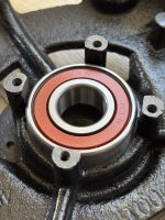
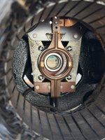
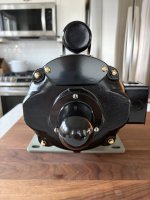
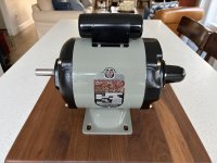
Bearings arrived yesterday, so I was able to finish up the motor and reassemble. I have to say, putting things back together after everything is cleaned up and freshly painted is definitely my favorite part of restorations. Here's a few more pictures and some more details.

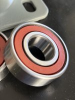
I went with Japanese made, NTN bearings which I think are one of the best options.

IMG_6147.jpeg


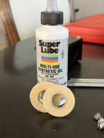
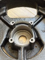
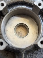
After the felt washers were cleaned up and re-impregnated with oil, the bearings slipped (or pressed) into place very nicely.
IMG_6167.jpegIMG_6168.jpegIMG_6169.jpegIMG_6170.jpegIMG_6174.jpegIMG_6175.jpeg

IMG_6178.jpegIMG_6177.jpeg
 
Last edited:
To avoid these ads, REGISTER NOW!
OP
C

chargedmr2

Well-known member
Joined
Sep 18, 2019
Messages
217
Location
WA
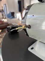
The end bells went back on very easily, after having cleaned up all of the original rust that had formed where the bells meet the motor housing. I fished the wiring back through the appropriate locations and closed things up, hopefully for the last time!IMG_6193.jpegIMG_6216.jpeg

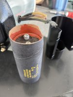
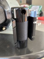
The capacitor housing and capacitor sure cleaned up nicely! Much better than how it started out, anyhow. Reassembly was pretty straightforward.
IMG_6203.jpegIMG_6198.jpegIMG_6213.jpeg

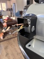
The electrical enclosure also turned out pretty nice and I decided to go with WAGO Series 222 Lever Nuts to secure the connections. These things lock down TIGHT and are designed for high vibration environments. I highly recommend them and this is the fourth restoration where I've put them into service.
IMG_6217.jpegIMG_6224.jpegIMG_6228.jpeg
 
OP
C

chargedmr2

Well-known member
Joined
Sep 18, 2019
Messages
217
Location
WA
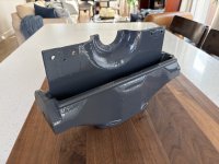
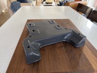
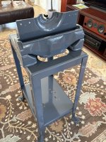
So, I decided to have the main components of the disc sander powder coated at a local shop. It's not an original Delta color like the motor is, but I think it turned out really nice! It's a dark gray that is more akin to the 1940s blue-gray that came on the Delta pedestal grinders. And since this sander is going to sit right next to my pedestal grinder that I restored in that color, I thought it would look good to match things up.

Anyhow, here are some pics of the freshly coated parts.IMG_6364.jpegIMG_6369.jpegIMG_6370.jpegIMG_6376.jpegIMG_6377.jpegIMG_6382.jpegIMG_6384.jpegIMG_6390.jpeg
 
OP
C

chargedmr2

Well-known member
Joined
Sep 18, 2019
Messages
217
Location
WA
Starting to piece things back together, and so far (knock on wood) my wife hasn't even complained about this tool being in the middle of our living room, lol. This is definitely my favorite part of the restoration process!IMG_6417.jpegIMG_6419.jpegIMG_6424.jpegIMG_6441.jpegIMG_6446.jpegIMG_6451.jpeg
 
OP
C

chargedmr2

Well-known member
Joined
Sep 18, 2019
Messages
217
Location
WA
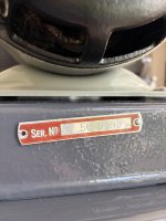
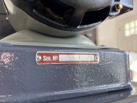
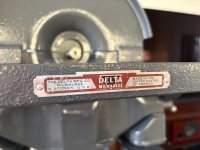
Always a pleasure putting the serial plates and badges back on as well! Still have to drill out some stubborn drive screws from the front of the table before putting the name badge back on. Might get to that later today. IMG_6497.jpegIMG_6498.jpegIMG_6500.jpegIMG_6509.jpeg
 
OP
C

chargedmr2

Well-known member
Joined
Sep 18, 2019
Messages
217
Location
WA
Thanks for the kind words, gentlemen.

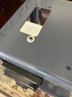
So, last night I drilled out the drive screws for the badge on the front edge of the table. Unfortunately, the darn things are so hardened that I couldn’t drill them out. Even with a fresh solid carbide bit. The bit walked off the remaining shaft of the drive screw and cut through the cast iron like butter. So I ended up with two “new” holes directly adjacent to the original drive screws which remained solidly in place. Despite the drama, it still turned out okay. The badge now sits about 3/32” lower than it originally did. I can live with that 😉IMG_6530.jpeg
 

Snip's

Well-known member
Joined
Apr 29, 2017
Messages
1,859
Location
Ohio
This PDF might help with getting the proper spacings during your reassembly...
 

Attachments

  • 3237.pdf
    156.8 KB · Views: 8
OP
C

chargedmr2

Well-known member
Joined
Sep 18, 2019
Messages
217
Location
WA
This PDF might help with getting the proper spacings during your reassembly...
This is perfect timing. I was just wondering about whether I should shim under the motor to center the motor shaft a bit better. Just eyeing it, I think it could sit about 1/4” higher than where it originally was.
 
OP
C

chargedmr2

Well-known member
Joined
Sep 18, 2019
Messages
217
Location
WA
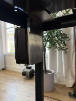
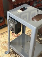
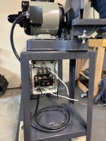
Little more progress. Got the AB magnetic motor starter installed. At first I was going to mount it dead center on the front. But I opted to mount on the back left instead. It feels much more natural to reach for that location to me.

I had some scrap aluminum in my shop, so I fabbed a mount that uses an existing hole in the stand. Worked out pretty good. IMG_6538.jpegIMG_6542.jpegIMG_6544.jpegIMG_6552.jpegIMG_6535.jpeg
 
Last edited:
OP
C

chargedmr2

Well-known member
Joined
Sep 18, 2019
Messages
217
Location
WA
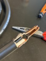
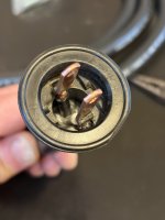
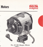
Made some more progress. The sander had the original power cord and after 79 years of use, it was definitely time for a replacement. The insulation was cracked throughout, and it was clearly not safe for use. I was planning to toss everything and start fresh, but I'm a sucker for original components so I decide to retain the plug. I'm pretty sure it's the same plug that's featured in the Delta catalogs. I was able to pry the plug apart, desolder the prongs, and reassemble with fresh 12AWG power cord. I probably should have replaced the plug since it's not a three prong plug (i.e., no ground), but I guess I'll live dangerously for now.
IMG_6596.jpegIMG_6601.jpegIMG_6604.jpegIMG_6606.jpegIMG_6608.jpeg
 
Last edited:
To avoid these ads, REGISTER NOW!
OP
C

chargedmr2

Well-known member
Joined
Sep 18, 2019
Messages
217
Location
WA
After getting the power cord and plug in order, I wired up the Allen Bradley starter and finally fired up the motor. I runs very smooth and very quiet on the new NTN bearings! Very happy with how things are coming along.

Next I need to clean up the platen, which I'm afraid might need a little work. It seems to have some minor warping and does cause some noticeable vibration that isn't present when just running the motor without it. IMG_6615.jpegIMG_6620.jpegIMG_6625.jpegIMG_6628.jpegIMG_6629.jpeg
 

Beerhippie

Well-known member
Joined
Oct 13, 2023
Messages
9,914
Location
Far NE Oregon
They are, but most I’ve seen are like 16 or 18 g wire, need to shop carefully. Or maybe I only shop at places that sell it for lighting.
The ones I've seen are also the nearly-rigid PVC insulated wires under the cloth cover.
 

RTM

Well-known member
Joined
May 13, 2019
Messages
13,214
Location
SF Bay Area
The ones I've seen are also the nearly-rigid PVC insulated wires under the cloth cover.
I bought some at Hippo Hardware, didn’t seem that bad. Was stupid $$ tho.

I’ve got a modern extension cord covered in Christmas colors, it’s a bit stiffer.
 
OP
C

chargedmr2

Well-known member
Joined
Sep 18, 2019
Messages
217
Location
WA
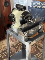
So, I finally got my disc sander all assembled and located back out in my shop.

When I first brought it home, I fired it up and immediately noticed that there was far more vibration than I was comfortable with. I knew I'd be returning to that issue eventually. And that's exactly what I've been working on most recently.

Here it is looking nice, but functioning pretty miserably!
IMG_7060.jpeg

I took the disc off the hub and tried rotating the mounting locations. That might have made a very slight difference, but no real improvement. When I placed a large wrench on the sander table it would walk right off the table in a matter of seconds. Not good!!

The motor shaft measured nice and true (about .0007"), so I figured the disc must have been way out of balance.

So, I set up a jig to static balance the disc.
IMG_7240.jpeg
IMG_7242.jpeg

It was pretty clear that the disc had an obvious heavy side, as it quickly rotated, then came to a stop and reversed direction. It went back and forth (MANY TIMES) and eventually settled with the heavy spot on the bottom. So, I marked the location, then scribed a an arc and started drilling. I was thinking it would take 7 or 8 holes. NOT EVEN CLOSE. I drilled the initial holes and the disc behaved just like it did initially. It quickly rotated, did its back and forth rolling, and finally settled in the same exact spot. So, I continued to add a couple of holes, test, and repeat. 25 holes later, the disc was FINALLY balanced . I could place it on the jig in any orientation and it would sit nice and still--no more rotating back and forth.
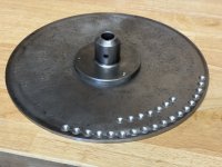
IMG_7255.jpeg
IMG_7250.jpeg

After it was balanced, I reinstalled the disc on the disc sander for the moment of truth. I've never balanced a disc before, so I was cautiously optimistic. I fired up the disc sander and at last, it ran VERY smoothly! No more wrenches walking off the table! I even balanced a 2.5mm Hex bit on the table and it hardly vibrated. That's mission accomplished in my book. And that's pretty much a wrap for the restoration. This is definitely a keeper, which is exactly what I plan to do with it.
IMG_7262.jpeg
 

larry4406

Well-known member
Joined
Jan 27, 2006
Messages
19,437
Location
Northern Virginia
Great job on the disc balance!

That is nuts it was that far off! How could it have ever been in service that way? Makes you think a balance weight got knocked off at some point in time, but its not clear to me where one would have been located.
 
OP
C

chargedmr2

Well-known member
Joined
Sep 18, 2019
Messages
217
Location
WA
Great job on the disc balance!

That is nuts it was that far off! How could it have ever been in service that way? Makes you think a balance weight got knocked off at some point in time, but its not clear to me where one would have been located.
Thanks! I’m sure glad it worked. I think the bearings will be much happier now, too!

I’m not sure these had weights added from the factory? Or if they were typically drilled for balance? Small stick on weights would probably be a lot quicker for doing a balance job, though.
 
To avoid these ads, REGISTER NOW!
Top Bottom