To avoid these ads, REGISTER NOW!

How to Beef Up an I-Beam?

zeebad1

Well-known member
Joined
Jan 2, 2006
Messages
256
Location
Northern Illinois
Here's my jib crane beam. .....

P3270009.jpg


Being the fact that the price was right, (free,) I think that I can make this work.

I have a thought as to how I can extend it 11', and make it 16" tall, instead of the 12" that it is currently.

P3270012.jpg


P3270014.jpg


I'm open to suggestions that might work better than what I have thought out.
I was planning on extending it with another piece, identical to the I-beam that I have, and truss the top of it with some 5" X 1/4" flat, with legs welded under it.

I just picked up a 1/2 ton electric chain hoist, (Ingersoll Rand Centurion,) and a Jet trolley today, so now I want to get this done. It looks like the hoist is an old one, but appears to be in very good shape.

I don't know where the hoist came from, but it has 50' of chain, and a 48' cord for the control. Must have been in a very tall building
 
To avoid these ads, REGISTER NOW!

YellowLakeWelding

Well-known member
Joined
Dec 21, 2010
Messages
110
Location
Wisconsin
Keep the height, ****-weld the new section then fish plate it on the sides and one on the top then bolt the fish plating. Add the truss to the top and that should support much more than the 1/2 ton hoist your planning on using.
 

GeorgiaHybrid

Well-known member
Joined
Sep 9, 2008
Messages
3,763
Location
Extreme NW Georgia
Let an engineer look at your problem but a W5 or a doubled up C5 (much easier to find a W6x15 or a double C6x8.2) stich welded to the top flange with a 1/4", 3-12 stitch weld would be a starting point for an engineer. When you splice the main beam, make sure your engineer specs a full pen weld of the flanges and uses a "diamond" shaped web plate (1/4" should do) on both sides of the web.

You will also need to change the end plate that connects to the column and fix the connection on that end (or add a brace from the top flange of the beam to a higher point on the support column). You have NO bolts on the compression flange (top flange) and there should be bolts above and below the top and bottom flange. This is a moment connection and should be looked at by someone with an understanding of moment connections (read STRUCTURAL ENGINEER).

I can't stress enough that your life is hanging by that beam. It's worth a few bucks to make sure you sleep in your own bed at night instead of under a bed of roses.....

Edit: Do you have the two stop angles that bolt to the two holes in the web on the end of the beam away from the columm? There should be two angles (usually 2 1/2x2 1/2x1/4 or 3x3x1/4 that prevent the trolley from running off the end of the beam).
 
Last edited:

Dragster Racer

Well-known member
Joined
Feb 9, 2008
Messages
1,891
Location
Morrison, IL
I haven't done much with structures, so not much help. I like the looks of it though. You are dealing with some heavy duty stuff there. I understand why you would want to make sure it is right. Can you imagine just that beam falling from its suspended height? Yeow!
 

JOHNMAN

Well-known member
Joined
Aug 14, 2006
Messages
194
Location
Southwest Indiana
What are you planning?

Are you planning on this beam to remain a Jib Crane or will it become a fixed monorail?

Jib cranes typically pivot about the support column.

Are you extending this beam 11'?

If you let us know what you are planning, it would be easier for the couch quarterbacks here tell you what you should be doing.

By the way, jib cranes typically require a SUBSTANTIAL mount as the load is always cantilevered out a long distance. Free standing (post mounted) jib cranes typically have huge footers that the columns are bolted to.
 

cal67ss396

Active member
Joined
Nov 29, 2010
Messages
34
Location
Central Indiana
I will have to agree with GH this should be reviewed by a structural engineer if you intend to extend the beam and increase the heigth. There are however a few things to take into consideration. The beam is already rated for a load of two tons and all structural steel at its base design has a safety factor of two built in. Don't know if the same rule applies to jib crane beam.

If you plan to extend the beam I would do more than but weld it and fish plate it. I would bevel it and prep it for a CJP type of weld and then have it ultrasonic tested. Another thing to keep in mind is that the type of beam you have is an S shape beam and not a W shape. If you do extend it you will need to get the same type. An S shape beam has the tapered flanges that allow the trolley to run up and down the jib. Extending the beam is something that should not be done without an engineers review.

As for increasing the heigth of the beam I am not sure what you are trying to accomplish by doing this. But if you want to increase the heigth the full length I would stack another beam on top with the same flange width. If you are trying to beef up the beam for strength. Something I would consider is to take a beam with the same flange with and split it down the middle basically making a WT. Then cut the WT on a taper and stitch weld it to the top of the jib. If needed I could send you some ACAD pictures of what I describing. I just think stacking beams will add unecessary weight if you are only going to be using a 1/2 ton hoist on a 2 ton rated jib. But then again I don't think you are going to get 1/2 a ton capacity all the way out on the end of the jib if hung in a cantilevering (sp) manner.

If you are going to hang this beam in a cantilevering (sp) manner I would definetly modify the existing mounting plate to include holes above the jib beam. The current design doesnt look real safe. How was it previously suspended? And yes a very important thing is to put on some safety stops both front and back of the beam.
 

GeorgiaHybrid

Well-known member
Joined
Sep 9, 2008
Messages
3,763
Location
Extreme NW Georgia
...If you are going to hang this beam in a cantilevering (sp) manner I would definetly modify the existing mounting plate to include holes above the jib beam. The current design doesnt look real safe. How was it previously suspended? And yes a very important thing is to put on some safety stops both front and back of the beam.


If you look close in the third picture, you can see where a top flange brace connected just above the two stiffeners. That should have gone to the column above the mount point for the beam. As for the end plate, it would appear to be about 3/8 thick and that is not even close to what would be needed for prying on a 4 bolt moment end plate. It should wind up at least 1/2" if not 3/4" or more. Adding 11' to that beam will make for one hell of a lever arm.

Without knowing the sizes of the material and the length of the original beam, we are just guessing though. Have a structural engineer look at it. Most steel fabricators have one on staff if they are of any size. They would also be able to source the material for you.
 
OP
Z

zeebad1

Well-known member
Joined
Jan 2, 2006
Messages
256
Location
Northern Illinois
Let an engineer look at your problem but a W5 or a doubled up C5 (much easier to find a W6x15 or a double C6x8.2)


Edit: Do you have the two stop angles that bolt to the two holes in the web on the end of the beam away from the columm? There should be two angles (usually 2 1/2x2 1/2x1/4 or 3x3x1/4 that prevent the trolley from running off the end of the beam).

Good idea with the W5, but I don't want to add that much weight. I don't have the stops, but they can easily be made.

What are you planning?

Are you planning on this beam to remain a Jib Crane or will it become a fixed monorail?

Jib cranes typically pivot about the support column.

Are you extending this beam 11'?

If you let us know what you are planning, it would be easier for the couch quarterbacks here tell you what you should be doing.

By the way, jib cranes typically require a SUBSTANTIAL mount as the load is always cantilevered out a long distance. Free standing (post mounted) jib cranes typically have huge footers that the columns are bolted to.

I guess I assumed that everyone had seen my "build" post. I didn't explain this clearly.

I already have the post.....

P5250021Small.jpg


and it's spec'd out to hold a 20' X 16" jib crane that is rated for 1000 lbs. The beam that I have was "scrap," (free) so I was thinking that I could make it work by making it the same dimensions as the beam that was designed for this application. The new one would cost over $1700.00, so I was hoping to use this one, with modifications.

I will have to agree with GH this should be reviewed by a structural engineer if you intend to extend the beam and increase the heigth. There are however a few things to take into consideration. The beam is already rated for a load of two tons and all structural steel at its base design has a safety factor of two built in. Don't know if the same rule applies to jib crane beam.

If you plan to extend the beam I would do more than but weld it and fish plate it. I would bevel it and prep it for a CJP type of weld and then have it ultrasonic tested. Another thing to keep in mind is that the type of beam you have is an S shape beam and not a W shape. If you do extend it you will need to get the same type. An S shape beam has the tapered flanges that allow the trolley to run up and down the jib. Extending the beam is something that should not be done without an engineers review.

As for increasing the heigth of the beam I am not sure what you are trying to accomplish by doing this. But if you want to increase the heigth the full length I would stack another beam on top with the same flange width. If you are trying to beef up the beam for strength. Something I would consider is to take a beam with the same flange with and split it down the middle basically making a WT. Then cut the WT on a taper and stitch weld it to the top of the jib. If needed I could send you some ACAD pictures of what I describing. I just think stacking beams will add unecessary weight if you are only going to be using a 1/2 ton hoist on a 2 ton rated jib. But then again I don't think you are going to get 1/2 a ton capacity all the way out on the end of the jib if hung in a cantilevering (sp) manner.

If you are going to hang this beam in a cantilevering (sp) manner I would definetly modify the existing mounting plate to include holes above the jib beam. The current design doesnt look real safe. How was it previously suspended? And yes a very important thing is to put on some safety stops both front and back of the beam.

I like the idea of splitting a beam, and tapering it both directions. I would only need a piece of I-beam about 12' long that way.

It will be going up as a jib crane on the post already buried in the concrete. I have to buy the components for that yet. That's going to cost about $1500.00, but that's what is designed for this.

Thanks for all of the suggestions, and definitely the advice to get a professional involved. You never know if you build something with
"overkill," but learn all too soon if it's not heavy enough. Sure don't want anybody getting hurt!
 

nissan_crawler

Well-known member
Joined
Jan 12, 2008
Messages
9,638
Location
Wichita, KS
Let an engineer look at your problem but a W5 or a doubled up C5 (much easier to find a W6x15 or a double C6x8.2) stich welded to the top flange with a 1/4", 3-12 stitch weld would be a starting point for an engineer. When you splice the main beam, make sure your engineer specs a full pen weld of the flanges and uses a "diamond" shaped web plate (1/4" should do) on both sides of the web.

You will also need to change the end plate that connects to the column and fix the connection on that end (or add a brace from the top flange of the beam to a higher point on the support column). You have NO bolts on the compression flange (top flange) and there should be bolts above and below the top and bottom flange. This is a moment connection and should be looked at by someone with an understanding of moment connections (read STRUCTURAL ENGINEER).

I can't stress enough that your life is hanging by that beam. It's worth a few bucks to make sure you sleep in your own bed at night instead of under a bed of roses.....

Edit: Do you have the two stop angles that bolt to the two holes in the web on the end of the beam away from the columm? There should be two angles (usually 2 1/2x2 1/2x1/4 or 3x3x1/4 that prevent the trolley from running off the end of the beam).

Unless I'm way off here (could easily be), we're looking at things differently. The pivot point of that column is not at the end, you can barely see the tube on the beam. the plate at the end with the bolt boles is for counterweight, if I'm not mistaken.
 
Last edited:

GeorgiaHybrid

Well-known member
Joined
Sep 9, 2008
Messages
3,763
Location
Extreme NW Georgia
Nissan,

You might be right but I haven't ever seen one made that way (with a counterweight)and a lot of shops around here have a small (up to 2 or 3 ton) jib crane to shift loads around the walls of their shops. I have seen a lot of connection types for them but nothing quite like this beam.

A lot is going to depend on how it will be connected to the column.
 

larry_g

Well-known member
Joined
Apr 28, 2007
Messages
16,893
Location
oregon
Looking at this from a pure layman’s point of view, Do you need the 16" height of the beam for the full length? Can you run a 16" high beam out from the post and then drop down to 12" for the length of the beam you have on hand? I would think that if analysis was done point to point for the full 20' length you would find that a tapered beam would do the job. Since tapered beams are not common then beams with parallel top and bottom are used.

Anyway just another way to deal with what you have, and what you want.

lg
no neat sig line
 
To avoid these ads, REGISTER NOW!

nissan_crawler

Well-known member
Joined
Jan 12, 2008
Messages
9,638
Location
Wichita, KS
Nissan,

You might be right but I haven't ever seen one made that way (with a counterweight)and a lot of shops around here have a small (up to 2 or 3 ton) jib crane to shift loads around the walls of their shops. I have seen a lot of connection types for them but nothing quite like this beam.

A lot is going to depend on how it will be connected to the column.

I've seen it at a relatives monument shop, however, I seem to remember the tube being the full diameter all the way through the beam, which this isn't. I'm not entirely sure what's going on with this thing.
 
OP
Z

zeebad1

Well-known member
Joined
Jan 2, 2006
Messages
256
Location
Northern Illinois
Yes, that is exactly what mine is supposed to look like. I just don't have the box to hang the beam on the post yet.

I was too lazy to look for a picture last night.

Thanks kool55.

Remember that my post is already capable of holding a 20' X 16" beam. I'm just trying to make what I have as close to that as I can. Not trying to go above & beyond the limitations of what is already there.
 

cal67ss396

Active member
Joined
Nov 29, 2010
Messages
34
Location
Central Indiana
Now seeing the pictures posted by 55 it looks like you need to get that box. :)

Makes total sense to me now, I feel confident in saying if you mount it as shown in 55 pictures I wouldn't worry.
 

WNYflyer

Well-known member
Joined
Sep 13, 2009
Messages
2,124
Location
Lockport, NY
Judging by the end connection on that jub crane it looks like the I-Beam requires a tie rod to connect the top flange back to the support post area. Probably a seperate piece/fitting required to connect all that to the post.
 

RBailey

Well-known member
Joined
Jan 17, 2011
Messages
339
Location
Dubai, UAE (Arabian Gulf)
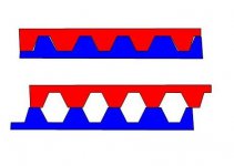
While manybe not that applicable in this case I have always loved the spliting the beam method.

You cut a "square wave" in the vertical sction then displace the beam and reweld where the beam touches.

In one step you increase the distance from netrual axis of the top and bottom sections (where the real strength is), thus increase the strength but at no increase in weight.

Common trick on some trailers and I'm sure there is a proper name for it but I don't know it.

Hopefully the attached quick sketch makes sense.

p.s. as always if you are doing anything structural CYA and get a profesional to check.
 

Attachments

  • Spliting I Beam.jpg
    Spliting I Beam.jpg
    14.1 KB · Views: 4

Notch1988

Well-known member
Joined
Feb 20, 2006
Messages
527
Location
Fort Saskatchewan, AB, Canada
There is a truck forum for 67-72 trucks that has a member that goes by lakeroadster. He's a mechanical engineer and helps guys out with beam analysis when they're doing notches for rear drops. Maybe give him a shout and see if he can help.
 

Cougar

Well-known member
Joined
Mar 22, 2011
Messages
3,361
Location
Wisconsin A little south of the Frozen Tundra
Are you going to build the head assembly or buy one.
May be a little tricky to build one with the roller assembly and the bearing race on top. Getting all the dimensions right.


Yes, that is exactly what mine is supposed to look like. I just don't have the box to hang the beam on the post yet.

I was too lazy to look for a picture last night.

Thanks kool55.

Remember that my post is already capable of holding a 20' X 16" beam. I'm just trying to make what I have as close to that as I can. Not trying to go above & beyond the limitations of what is already there.
 
OP
Z

zeebad1

Well-known member
Joined
Jan 2, 2006
Messages
256
Location
Northern Illinois
While manybe not that applicable in this case I have always loved the spliting the beam method.

You cut a "square wave" in the vertical sction then displace the beam and reweld where the beam touches.

In one step you increase the distance from netrual axis of the top and bottom sections (where the real strength is), thus increase the strength but at no increase in weight.

I like the looks of that!! I know that I have seen structures of this sorts, but didn't realize how simple they were. It would be a lot of cutting with a plasma cutter, but I like the thought of not adding any weight.

There is a truck forum for 67-72 trucks that has a member that goes by lakeroadster. He's a mechanical engineer and helps guys out with beam analysis when they're doing notches for rear drops. Maybe give him a shout and see if he can help.

I'll see if I can track him down. Thanks for the lead.
 

WNYflyer

Well-known member
Joined
Sep 13, 2009
Messages
2,124
Location
Lockport, NY
I was mistaken on the need for the tied rod. Like you said you need the end piece that connects the beam to the post.

Take a look at the attached link for boom/beams size versus span versus capacity. Looks like if you down rate your capacity to 1/2 ton from 2 Ton you might get away with just **** welding (CJP) on a new piece of S12.

You maybe able to call Columbus Mckinnon (Abell-Howe)and get some details on what you have presently and on one that will hold a 1/2 ton at the span you want. Then compare and see if you have to do anything other than adding a piece of S12.

http://www.abellhowe.com/AbellHowe/j904spec.aspx
 

kartracer55

Well-known member
Joined
Jun 21, 2005
Messages
5,317
Ok,

I'm not going to play engineer here for legal reasons, but I'll say this.

1) This beam could easily be extended in height, provided accurate fixturing (IE machine table) is used to do so and proper engineering practices are followed. I'd talk to an engineer (hopefully a buddy who likes fancy beer) and ask about some key phrases like "doubler", "E/D", and "Match Drill". I would not venture into this without some thorough calculations being done by the engineer, because your life is at stake.

2) I would not consider extending this beam in length, especially in the cantilever configuration. Even in a gantry type setup, the joint between the two would require thorough analysis, as would the the overall support structure. Also, the end joint would be tricky because you can't really design something like this to rely solely on a DIY weld. Some trick bracketry and properly designed bolted connections would be required, so I wouldn't try and go at this without some proper design by somebody trained (and hopefully experienced!)

If you can find the ]ndividual consultant, Id say the full design of this is less than a day's work for somebody familiar and it could probably be signed off on for less than 1k by a part time/semi-retired consultant looking for a neat project. Might not hurt to look around.
 
To avoid these ads, REGISTER NOW!
Top Bottom