To avoid these ads, REGISTER NOW!

The Old Milwaukee Express

cnc-me

Well-known member
Joined
Jan 6, 2010
Messages
1,183
Location
MI
Hi all, this thread will be the building of the Old Milwaukee Express, racing lawnmower (AKA Go-kart).
This first post will be on the fabrication of, two into one headers for the B&S Vanguard engine.
The pictures shown here are of an earlier racer that Mark built.
Mark is the driver of this machine, and he got into a bad wreck with it in 2009 which destroyed it,
and was not to good on Mark either (2 cracked ribs).
In the winter of 2010 we decided to build a whole new racer from scratch, using some of the parts from the old one like these headers and the engine.


Here is Mark sawing out the flanges which bolt to the exhaust ports.


2 into 1 collector ready for welding onto the head pipes.


Template for the megaphone.


Megaphone


This is Duane, our engine tuner running some TIG welds.


Eat your heart out Vance & Hines.. :)


I put a piece of category 5 net cable down each pipe to check for length.
They are within 3/16" of being the exact same length, close enough...


Post #2 will be on the building of the new chassis which will incorporate these
headers shown above.
 
To avoid these ads, REGISTER NOW!
OP
C

cnc-me

Well-known member
Joined
Jan 6, 2010
Messages
1,183
Location
MI
Post #2 Happy Easter

Here is some of the tracks we race on.

Ithaca Dirt Devils
http://ithacadirtdevils.com/default.aspx

Maple Rapids Grass Kickers
http://www.mrgrasskickers.com/index.html

Potterville Rough-Riders
http://www.rough-riderslawnmowerracing.com/

Why Old Milwaukee? Its cheap and its good. (At least we think so)
Drank quite few gallons of the stuff back in our younger days.
Come to think of it we still do. :)
Besides, we would not get any flack from other racers if
we called it the Budweiser Express.

Here is the can that started it all. A Boyd Coddington limited edition.
Mark, even took this can to the paint store to get the color matched
for paint on the new racer. The guy at the counter, got a few laughs,
said he never had anyone bring a beer can in for color matching.


Beer built right logo scanned from the beer can itself and
redrawn in Auto-Cad. The Auto-Cad drawing will be used to create the
final logo to be cut from vinyl at the local sign shop.


Enough silly nonsense.
Here is the power behind this project a Briggs & Strattton Vanguard
23 HP overhead valve engine.
It has had extensive head and valve work by Duane.
It sports oversize Yamaha and Mazda valves.
It also has my custom machined aluminum head gaskets made to
Duane's specs. It also has an ARC aluminum flywheel and
ARC aluminum rods and a Precision Cam.
We are still using the stock dished pistons because
it runs good enough, and will easily run for a whole season.
Traction is more of an issue with this thing, than raw horsepower.


Went to high tensile steel studs instead of the stock bolts.
We are building a pretty big fire in this thing and want to make sure
it all stays inside.


Mark, looking on while Duane works his magic. :bounce:


The Vanguard is also equipped with these dual 26mm Mikuni slide carbs.
We did not want to get silly with the size of these things, as the
Vanguard is a lawnmower motor. Got them off E-bay new. They are
set up for a 2-stroke motorcycle. Does not matter as most of the
brass is going to be changed anyway.
Bolted up to the heads are my custom made aluminum billet
intake manifolds. (No pictures of the intake manifold machining, just what
Mark took with his phone, and they are super small :( )
Both manifolds are the same length, the engine has a
stagger in the cylinders.


The new numbers for the Vanguard are
right around 35 H.P. with a top RPM of 7800 according to Duane's
Mustang chassis dyno. Not to shabby, especially with all that
nice flat torque. Throttle response is fantastic. It even surprised Duane,
how fast this thing revs up. I have seen some motorcycles that don't
respond as good as this thing does.
It sounds more like a car, than a motorcycle though, and it defiantly does
not sound like a lawnmower engine, at all.
In fact one of the neighbors that lives close to the Ithaca track
thought someone had a car on the track and came over to see, as
they are not allowed to have cars on the track.
I can still see the guy looking for the other six pipes. :)


The Vanguard all nestled in her new home.


More to come in #3
 

e3pres

Well-known member
Joined
Sep 5, 2006
Messages
168
Location
Chattanooga, TN
There is a track across the street from some land that I own near Chattanooga, TN. Those thing are as fast as they are dangerous... and they are plenty dangerous. :D
 
OP
C

cnc-me

Well-known member
Joined
Jan 6, 2010
Messages
1,183
Location
MI
There is a track across the street from some land that I own near Chattanooga, TN. Those thing are as fast as they are dangerous... and they are plenty dangerous. :D

They sure are, we have had people at are tracks get hurt before.
We have had broken legs, had one guy that had a flywheel blow up
with pieces of the flywheel embedded in his leg. The bad thing was,
this was the first race of the season, and the ambulance was not on the
track grounds as it normally is, so it took a while to arrive.
Right after that little incident, they outlawed all "cut" (lightened) flywheels.
 
OP
C

cnc-me

Well-known member
Joined
Jan 6, 2010
Messages
1,183
Location
MI
Post #3 will cover the frame and rear axle adjusters.

From raw steel and aluminum stock, all the way to the checkered flag.
Let the build begin. :)

Axle shaft is 1-1/4" hollow chrome moly steel.
The rear chain adjusters have about 2" of travel.


Rear disk brake protector is made from 1/4" plate aluminum.
Bracket with 3 holes, in lower right corner is the fender mount.


TIG welds holding the rear axle mount in place.


The rear bumper will cover the ends of the tubes, so no dirt will be able to enter.


Steering frog assembly ready for welding into the main frame.
The two holes were drilled, and then reamed for ground taper pins, like
what is used on machine tools, instead of the cheaper,
and harder to remove roll pin.


Tie rods shown here will not be used, going to be making new ones
from 9/16 aluminum hex stock.


Grease zerk on top, brings lube down to the two bronze bushings
through a cross drilled hollow shaft.


Small bracket in the lower right is for the clutch spring adjuster.


More to come
 
OP
C

cnc-me

Well-known member
Joined
Jan 6, 2010
Messages
1,183
Location
MI
Post #4 will be on the drive line parts and the belt guard.
As you can see, we are using a horizontal shaft engine, most racers in
our area, all use a vertical shaft. The problem with the verticals is,
the transmissions, you have to use in order to be legal for the
intended class. Most likely a Peerless 700 series like the one below.


The 700's are ok for the 12 horse flat-heads but anything much bigger
will rip the bevel gears right out of them.
We decided to bypass all these problems and opted for a
direct drive set-up like the diagram below.

We use an electric clutch for neutral, as well as a foot clutch.
Operation goes something like this,
Push in spring loaded foot clutch.
Turn switch on to electric clutch.
Ease out on the foot clutch and take off.
Should work like a champ, right? It does, except for one
small problem. With only one gear, its geared a little high for
navigating the pits, but works great out on the track.
We have not had a single problem with this setup.


We wanted a nice aluminum secondary pulley, but could not find any, for a decent price.
The picture below shows a 9" steel pulley from a farm store that is being lightened.
Once again, an Auto-CAD drawing is being used for layout, its held down with
spray on contact cement.


We purchased an 11/16" weld on hub, and later bored it to 3/4" after the outside
rim of the pulley was running true in the lathe.
By doing the welding first, you get rid of all the run-out
a weld on hub like this normally has.


A couple passes in the keyway, with a 3/16" broach and we are done.


My late 60's vintage Clausing 14 x 48


The belt guard under construction.
The pulley is off the old racer and used for test fitting only.
In the bottom center of the picture, you can see the clutch spring hanging.


Shown here is the jackshaft.
I got Mark to mill the keyways in the 3/4" 4140 shaft.


Here is my belt guard template, its made from 1/8" Masonite.
I had to make a couple of revisions to it, before we actually cut any aluminum.


Guard is mostly done here, as I am welding on the bracket for the jackshaft mount.


The raised area with slot is for the belt guide. (More on those later)


Bolted up to the jackshaft tower.


Clutch arm
The large hole is 1" with the tapered pin cross hole
The hole in the small end is for lightning only.


The idler pulley will go into the hole at the top of the picture.
A large spring from a John Deere will connect at the bottom.
Pivot has two bronze bushings and a grease zerk for lube.
Check out my exclusive slide over the frame rail, mounting system.


The combination clutch restrainer and belt guard mounting bracket.
The hole next to the angled part had to be filled in.
As it was for a different clutch restraint that didn't work out.


This setup worked out very well.
Those ball joints hook to the electric clutch, to keep it from spinning around the engine's crankshaft.


More To Come
 
OP
C

cnc-me

Well-known member
Joined
Jan 6, 2010
Messages
1,183
Location
MI
Post #5 Will be on the chain guard,the dash and some steering parts.

Chain Guard
Aluminum tacked into position.
Just bent it around the base with my hands, its so soft compared to steel.


Just hit this a little, with the DA sander.


Here you can see the flair at the end of guard, it really stiffens up the guard
in case the chain should hit it.


Red arrow pointing to the chain guard.
Off to the left is the jackshaft tower all marked up for lightning holes.
I thought we should wait to the end of the project before we actually
drilled them,in case we had to mount something to the tower.
It turned out to be a wise decision.


Dash & Steering
Don't have any bending equipment so the old 6" vise gets the job of
bending the .080 thick aluminum. I'm using plastic to keep the aluminum
from being scratched.


Allen bolts shown here are black oxide finish,which will rust the first time
the machine is washed. The final assembly will use stainless steel bolts.
The four small holes on the frame work are for the one gallon gas tank.
We cheated, and bought the tank from American Powersports out of Ohio.


1-1/2 square Aluminum post that will hold the steering shaft.
This was scrap aluminum, and would you believe, it already had the
corners knocked off, and even the bevel at the top was already done.
All I had to do was bore the hole and put in the zerk.
I guess ya gotta get lucky once in a while. :bounce:


The dash is designed to fit an old Craftsman II tractor hood, someone
gave Mark. The hardest thing was figuring out the angles needed
to be cut for the frame work. The sides are a compound angle of
8 degrees one way and 20 degrees in the other.
Would be easy to cut with a compound miter saw, if I had one. :)
Making a fixture was out of the question for just a few cuts
so I just cut one angle with the miter saw and finished them with
my Delta belt/disc sander using my trusty MITER GAUGE.
The headers are mounted up for a test fit.
Mark put some high temperature black paint on them.
Recycling the headers turned out to be a major PITA :(
as they put to many constraints on the design of belt guard and
various other things. Wish we would have made new ones
that exited out the right side of the machine. Oh well, it came out nice,
just a lot more work is all.


Steering shaft made from 7/8 OD x .156 wall drawn over mandrel tube.
We got a short piece, and it is not cheap but worth it.
Don't want anymore accidents like we had with the other racer.
If you look back a few pictures you can see how the steering post
assembly bolts on with four bolts. The reason is the top plate for
the handle bars will be welded on for safety concerns
and so will be the bottom pitman arm.
The idea was to pull the whole assembly out through the dash in case
the steering shaft ever had to be replaced.
The gas tank has some really nice TIG welds on it.


Here you can see the bolts off center. This was done to avoid crushing the
aluminum tube as its always the weakest if you bolt in the center of it.
It also doesn't hurt to have a little more clearance for the hood.


Here is the handlebar mount, and the pitman arm that will be welded to
the bottom of the steering shaft. The handlebar mount is designed for
Polaris Indy 650 snowmobile handlebar clamps.


I faced the bar mount off, in the Lathe
so its nice and square with the steering shaft.


More to come
 
Last edited:
OP
C

cnc-me

Well-known member
Joined
Jan 6, 2010
Messages
1,183
Location
MI
I wish I had one to cut the lawn with

I don't think it would work to well for cutting.
Its better suited to shredding or maybe cultivating. :)
We are supposed to have a fake mower deck mounted
on both sides of the racer, to be legal to race.
We never bothered put one on.
 
OP
C

cnc-me

Well-known member
Joined
Jan 6, 2010
Messages
1,183
Location
MI
Wow! You guys take your hobby seriously! Lot's of hours in your project and it shows.

Its just like any other form of racing, only slower and a lot less money. $$

That twin must sound pretty cool.:thumbup:
Sounds great ripping down the back stretch with
the front end in the air, until he chops the throttle.
That was another problem we had with the old machine we finally had to
put weights up front.
 

Zengineer

Well-known member
Joined
Apr 10, 2010
Messages
781
Location
British Columbia, Canada
Comment about chain guards. If you make it so there is very little clearance between the drive sprocket and the guard, the chain will tend to get "spit out" off the drive sprocket if it breaks. The alternative is generally a high speed flail that will destroy most things it hits...
 

89GLH

Well-known member
Joined
Mar 24, 2011
Messages
1,057
Location
Westminster, MD
What are we looking at? Can you take a wider photo of how it sits? Only reference I have is the frame, and a lot of zoomed in pictures. :)
 
OP
C

cnc-me

Well-known member
Joined
Jan 6, 2010
Messages
1,183
Location
MI
Comment about chain guards. If you make it so there is very little clearance between the drive sprocket and the guard, the chain will tend to get "spit out" off the drive sprocket if it breaks. The alternative is generally a high speed flail that will destroy most things it hits...

This is true.
Honda dirt bikes are a very good example.
They have a flat piece of stock that runs close to the chain rollers.
 
OP
C

cnc-me

Well-known member
Joined
Jan 6, 2010
Messages
1,183
Location
MI
Post #6 is just more pictures showing the progress so far.
Most of these pictures were taken on April 26, 2010.
We really had to hustle to make it in time for the 2010 season.
We fully assembled the machine, to make sure everything was working
correctly. Then we ran a couple of races with it, and then on
Memorial Day weekend we took it all back apart and sandblasted and painted it.

Jackshaft tower with 3/4" flange bearing from TSC.
The shaft shown here is just a dummy test shaft, from the old machine.
The new shaft will be longer with a hole tapped in the end of it to help
hold the sprocket on.


Jackshaft tower showing the pilot hole for the flange bearing.
The four tapped holes are for the belt guard.
Going to drill some more lightning holes in this once everything checks out.


The aluminum L shaped brackets in the foreground are for the hood mount bolts.


The "over the frame rail mounting system" worked so well on the clutch arm
decided to use it on the dash framework as well.


The hole at the front, in the running board, is for the headers to pass through.
I set this up so you could remove the headers from the engine without taking
the megaphone off. This racer is going to be easy to work on, if I can help it.
There was some real issues with the old machine as far as to be able to
get at things like the oil filter.
The belt guard on the old machine required removing the headers just to
put a new belt on. If you had any belt problems during a race, you were
essentially screwed as you would never be able to get a new one on in time.
With the new setup its less than a 5 minute job.


This is the only machine, at any of the tracks that we go to, that has this direct drive setup.
Everyone else is running a vertical shaft engine with a Peerless 700.
Maybe some of them will see the light in 2011. :)


In the lower right you can see the front disc brakes.


Had to hack on the hood so the headers would have clearance. Plasma cutters sure do work nice, for that kind of thing.


More to come
 
Last edited:
OP
C

cnc-me

Well-known member
Joined
Jan 6, 2010
Messages
1,183
Location
MI
Post # 7 covers a whole slew of sub-assemblies

Running Boards
The running boards are made from 1" square aluminum tube and then covered
with 1/8" aluminum diamond plate, welded on from the back side.


Here the headers go through an open area in the running board.
The header mount is a piece of black rubber hose, to provide flex for
vibration and thermal expansion.
After two seasons of running these headers, I can't see any cracks in them.
The megaphone just slips over the collector and is fastened with two bed springs
and is also mounted to the frame, with a big rubber grommet.


The round aluminum tube is the clutch pedal.


Diamond plate welded on.
Tthe diamond plate looks cool but is kind of slippery, especially when it gets wet.
Mark added a foot rest, on the right hand running board to keep his foot in place.


Header Mount
This was cut from 1-1/2 square tubing to form a mini channel.
The top channel is left long, it will be cut off to the proper length later.
The rubber hose mount on the headers will set up against the round area.


Two allen bolts hold the whole works to the running board.
To the right you can see the clutch pedal adjustment.


The headers should be protected quite well sitting behind the frame rail like that.


Fender Mounts


The big holes are drilled for weight.
1/4" nuts are welded on the backside. these will be used
to attach the aluminum fenders.


Checking fit before welding assembly to frame rails.


This is the U shaped frame that holds up the rear fenders and also the seat.
The big holes are for weight only. This is the only part of the frame, on this
machine to be drilled for lightning holes. Because no dirt will collect in them when its
mounted in its proper position. Its shown upside down here.


Drilling the fender support bar with the 1955 Walker-Turner drill press.


Seat Mount
A 1996 Honda Magna motorcycle seat is going to be used.
This is the mount I made for the Honda seat.


Template for seat mount reinforcing plate.
This was 1/8" aluminum cut out and bent to follow the square tube frame


We found that having some place to grab on to machine is really handy for loading, or just
turning it around, So I integrated this handle into the seat mount.
Will be adding another handle on the front bumper also.


With these two bolts and two more in the front, you can take off the seat and its mount.


Battery Box
All mitered and coped and ready to weld.
99420140.jpg


The side ears are 1/2" keystock. These will be drilled and tapped
after welding to accept a 3/8 threaded rod that will be used to hold
the battery in place.
20784981.jpg


Here is my homemade tapping jig in action
67491397.jpg


The smaller hole next to the frame rail is for the negative
battery cable connection.
65526722.jpg


Bumpers
That's the other grab handle on top of the front bumper.
This is the biggest front bumper that we are allowed to run on these machines.
That block of aluminum in the center, is a homemade hydraulic brake manifold.
We might put a proportioning valve on later, instead of the manifold.


The black perforated stock is from an old satellite dish antenna.
I'm going to cut out some numbers,
out of UHMW plastic and bolt them to the perforated stock.


The seat is purposely offset to the left.
The perf stock looks sweet and keeps the rocks off the other drivers, its only
downfall is that its a ***** to clean.


Numbers
Here we are jumping ahead of the story, a little with the paint on and all.


Some more stainless steel bolts holding on the numbers.


Here's whats left after I got done routing out the numbers with the CNC router.


At one time we had two machines #96 & #97.


More to come
 
To avoid these ads, REGISTER NOW!

kbs2244

Well-known member
Joined
Nov 11, 2006
Messages
14,065
This is how they do it down under.
 

Attachments

  • lawn mower drags.jpg
    lawn mower drags.jpg
    86.2 KB · Views: 228
OP
C

cnc-me

Well-known member
Joined
Jan 6, 2010
Messages
1,183
Location
MI
Post #8 is on the Front Axle & Front Brake Mount.

Here we are aligning a rotary table to the mill's spindle, in preparation
for milling a curved slot for the caster adjustment.


There is a lot of different ways to make a slot lot this, but this one does
the nicest job. Its also fairly fast once you get it all set up.
I made 4 of these plates even though I only needed 2, because 4 can be
made almost as fast as 2. So we have some spares or maybe I will
build another racer for myself.


My 1987 Enco mill, complete with homemade power feed unit on the right side.


Completed plate butted up to 1"x 2" steel rectangular tube.


The plates set at an angle to the tube and the alignment is fairly critical.
Rather than trying to clamp this all together I drilled two temporary holes
in the center of both plates, and then a 1/4" threaded rod was used to tighten
the plates against the tube. Then it was just a matter of tapping the plates
around with a small hammer until they were in the correct position.
Using a threaded rod like this also made it easier to weld because no
clamps are hanging from the outside and blocking my view.


The whole assembly was laid on the welding bench, and checked to make
sure both plates were in the same plane.
After welding I will pull out the threaded rod.
Just going to leave the two holes as they don't hurt anything.


The ball joints are a stock item, they are just like what you would use
for tie rod ends. By turning a nut back and forth you can rock the
tires in or out. (camber adjustment) I think this setup is common in
cart racing but not so much for lawnmower racing.
We pioneered this setup at our racing clubs in 2004.
Now most of the modified class lawnmowers all use some version of this.


The front disc brakes are a kit from Martin Custom Products.


Front Brake Mount
A piece of aluminum is clamped between the caliper mount and
the disc brake to insure that the mount is parallel with the disc.


Here is a big overall shot. This must have been taken shortly before the
first race at Ithaca. The Burris rear tires work ok, but we were having
problems finding enough traction. Mark talked a fellow racer into letting
him try out a pair of Hoosiers, that were much wider. With the other guys
tires on, he knocked about 2 seconds off his lap times!
Damn we were spinning even more than we thought.
Thats the last time the Burris's were run on the back after that.

:beer:
More To Come
 
OP
C

cnc-me

Well-known member
Joined
Jan 6, 2010
Messages
1,183
Location
MI
Post #9
Just some more pictures of the chassis, before it heads off to the first race at Ithaca.

Charging up the battery with a trickle charger.
The ARC flywheel on the Vanguard does not have magnets in it,
so there is no charging of the battery by the engine.
You can see the magic marker lettering system is in full effect.
We had the hood all doodled up as well.
Might as well have some fun before we put the paint on.


The fenders are made from aluminum trailer fenders that were
bent up in a few places. Only needed about half of each one,
so I just cut out the bad spots. Not exactly the radius I would have
picked, but they don't look to bad.
We are running the rear axle all the way to the front,
we usually have it in the middle.


Everything seemed to work pretty well, the first time out with
the new machine, except Mark had another machine get into one of the
idler arms and bent it up pretty bad. He brought her back into the
pits and we got it straightened out good enough to run the feature.
Here you can see the idler arm (its painted black) before we added a rib on top of
them to beef them up. This was one of the reasons we wanted to
run this thing before it was painted. Just like E.J. Potter used to say:
"You never know when your going to have to take the cutting torch or welder after it."
I for one would rather do all that before it has the paint and decals on it.


Post 10 will start the final assembly after sandblasting & painting.
and hopefully wrap this up.
:beer:
 
OP
C

cnc-me

Well-known member
Joined
Jan 6, 2010
Messages
1,183
Location
MI
Post #10 This post will cover the completion of the
Old Milwaukee Express. :beer:

We got our blasting and painting all done.
Now its time to put down the TIG torch, crack open some Old Mil's, and bust
out the wrenches, to put this contraption together for the last time.


After racing all of the 2009 season, the Vanguard suffered a broken
camshaft during the second race of 2010. Luckily, nothing else was damaged,
in the heads. A new cam was installed, and we proceeded to race the rest of
2010 without incident. I had to cut a round circle out of yellow vinyl to
cover up the Kohler label, as everyone thought we were running a Kohler.


Here you can see the "beefed" up idler arms with the extra rib across the top.
Hopefully they will be strong enough, so we don't have anymore incidents like
the first race at Ithaca.


Before I sandblast anything, I always go around with the heat gun to remove
any stickers and decals, but for some reason I missed a piece of foam rubber stuck
on the under side of the hood. I had already started blasting the hood, when I noticed the foam rubber.
I figured if I was careful I could just blast that off without having to get the heat gun out again. Everything looked good,
until I turned the hood over, right side up. You could now use the hood
for a washboard. Nice job dumb ***. Now what, I really don't want to get a
new hood as their was quite a bit of work that went into this one.
I'm not a very good body man but thought, what the hell, its junk anyway.
I banged around on this thing for 3 or 4 hours, was starting to look almost
as good as before I blasted it. :) I thought I am not putting any Bondo
into this thing at all, but eventually had to give up, and use just a little.
Its got its share of primer though. Lesson learned, haul out the heat gun
no matter what, especially on sheet metal.


Here you can see the aluminum air filter cover.
Its what I call "The Wart" its made the same way the chain guard was.
Its held on with a bizillion stainless steel bolts mostly for looks.


Installing the clutch pedal spring.


The Skipper (Mark) and his new ride.


This is why we should call our race team "Pyramid Racing"


And here's the guy that built this machine....
The thing that I am the most impressed with this whole
project, is that we were able to race a whole year with no
mechanical problems with the chassis.
No belt or chain problems what so ever. We did have a collision though,
but that doesn't count. And unfortunately the engine had some cam problems.
Now I can actually watch some of the races instead of being
in the pits..........:beer:
-John
 
Last edited:
OP
C

cnc-me

Well-known member
Joined
Jan 6, 2010
Messages
1,183
Location
MI
Bad A$$. Any video up of #97 in action?

jhn9840
John

She's quite the hot rod mowchine. :pimpflash
Yes, but its still on DV tape.
Let me look, I might have some on DVD,
that would make the upload much faster.
 

kbs2244

Well-known member
Joined
Nov 11, 2006
Messages
14,065
You sound proud.
And you should be.
That is some of the nicest fab work I have seen.

It just goes to show that you don’t have to be a multi million dollar outfit to collect some talent and be able to show the results with no shame whatever.
 
OP
C

cnc-me

Well-known member
Joined
Jan 6, 2010
Messages
1,183
Location
MI
You sound proud.
And you should be.
That is some of the nicest fab work I have seen.

It just goes to show that you don’t have to be a multi million dollar outfit to collect some talent and be able to show the results with no shame whatever.

Thank you very much.
Its been quite the journey into building this.
Everyone pitched in their area of expertise.
This is definitely outside my area of expertise as I
more accustomed to building/rebuilding machine tools.
-John :)
 

Zengineer

Well-known member
Joined
Apr 10, 2010
Messages
781
Location
British Columbia, Canada
While the racing series isn't necessarily my cup of tea, I love a good fab project, and you did an excellent job!

Now you've got me looking at my Craftsman 22hp sideways... It always needed more power....
 
OP
C

cnc-me

Well-known member
Joined
Jan 6, 2010
Messages
1,183
Location
MI
Post 11 Is some underside shots.
Shot of the steering arm. The drag link to the steering frog is removed
because, this is setting on saw horses and they would bend the linkage.


Here you can see the jackshaft cage.
Originally this was supposed to look like a transmission
but it started to get a little heavy, so I changed my mind and now
it looks more like a guard.


Round chrome thing, with the red plug in the center, off to the left is
an oil catch can for the engine.


Not much space anywhere, glad I was able to pack it all in here,
and still be able get at the things that will require service.


Eventually, I will get some video uploaded. :)
 
OP
C

cnc-me

Well-known member
Joined
Jan 6, 2010
Messages
1,183
Location
MI
While the racing series isn't necessarily my cup of tea, I love a good fab project, and you did an excellent job!

Now you've got me looking at my Craftsman 22hp sideways... It always needed more power....

Thanks,:)
 
OP
C

cnc-me

Well-known member
Joined
Jan 6, 2010
Messages
1,183
Location
MI
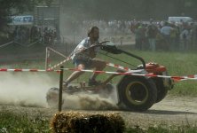
Action shots

Maple Rapids 7/11/10


Maple Rapids 7/25/10


Potterville Invitational


To avoid these ads, REGISTER NOW!
Top Bottom