To avoid these ads, REGISTER NOW!

No more gas - going electric - compressor conversion

Steevo

Well-known member
Joined
Aug 18, 2009
Messages
8,738
Location
43.49600, -112.04300
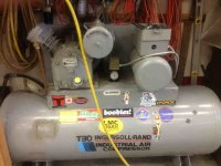
I was looking for a new compressor, when I came across a deal I couldn't pass up. I found an Ingersoll Rand T-30 two-stage compressor, without engine, for $200.

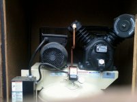
This compressor has a 30 gallon tank, and a 2475 compressor pump. It originally came with a Kohler 11HP gas engine, and is sold primarily as a mobile service truck compressor.

Since the 2475 pump alone currently sells for between $1100 and $1500, I felt that $200 was more than reasonable for the pump and tank.

IMG1290-M.jpg

IMG1285-M.jpg

IMG1288-M.jpg


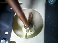
I'll need to remove and cap off the pneumatic throttle control pictured here, and add an electric pressure switch in that plumbing, but other than that, I think it will be as simple as bolting on a 5HP electric motor and finding a pulley that will accommodate the dual-row belt it came with.

IMG1286-M.jpg


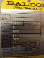
I am thinking I'll go with a 3600 rpm motor, with pulley sized to give me +/- 1000 rpm at the pump (about 3.75"). According to IR spec sheets that will give me about a 16.5CFM @ 175 PSI pump setup.

Any advice or feedback relative to experience with converting a gas compressor to electric will be appreciated.
 
Last edited:
To avoid these ads, REGISTER NOW!

1steve

Well-known member
Joined
Mar 28, 2011
Messages
275
Location
Tennessee
Yes you ****! Simple straight forward swap, motor, pressure switch, pulley.
What brand motor you thinking about?
 

trbomax

Well-known member
Joined
Mar 21, 2010
Messages
2,556
Location
starvation lake,mi.
I'm not sure a 3600 rpm motor will have enough starting torque,or even enough power at all to run that pump at 1000rpm. I had a 5 1/2 1650 rpm motor on my t-30 and it really did not like startups,to the point that about 2 yrs into its life it smoked up and died. I replaced it with a 7.5 1650 rpm and its been good for 35 + yrs now,and thats running at about 875rpm. I was dealing with old school cap start motors that generaly will take more abuse than newer ones. Anyway,its still running today,at 875rpm.

edit) the old girl is a bit dirty and nappy in the pic,that was right after I moved it up here and it was sitting in one of the other pole buildings for a couple years.Stated right up though!
 

Attachments

  • IMG_0813.jpg
    IMG_0813.jpg
    133 KB · Views: 317
Last edited:
OP
S

Steevo

Well-known member
Joined
Aug 18, 2009
Messages
8,738
Location
43.49600, -112.04300
trbomax,
The reason I was leaning towards a 3600 rpm motor is because the specs for the pump say it should be operated at 1000 rpm with a 5HP motor, and since the pump pulley is 13.5" dia, I figured the 3.75" or so motor pulley needed to hit 1000 pump rpm would give the motor a good mechanical advantage compared to a 7.5" pulley on a 1740 rpm motor.
Anyone, feel free to school me on motor loads and pulley ratios.
 
OP
S

Steevo

Well-known member
Joined
Aug 18, 2009
Messages
8,738
Location
43.49600, -112.04300
Yes you ****! Simple straight forward swap, motor, pressure switch, pulley.
What brand motor you thinking about?

Well, since I am only in it for $200 now, I was thinking about a good, quality motor like a Baldor, if I can find one for $400 or less. That way, it is still a good deal.
 

trbomax

Well-known member
Joined
Mar 21, 2010
Messages
2,556
Location
starvation lake,mi.
trbomax,
The reason I was leaning towards a 3600 rpm motor is because the specs for the pump say it should be operated at 1000 rpm with a 5HP motor, and since the pump pulley is 13.5" dia, I figured the 3.75" or so motor pulley needed to hit 1000 pump rpm would give the motor a good mechanical advantage compared to a 7.5" pulley on a 1740 rpm motor.
Anyone, feel free to school me on motor loads and pulley ratios.

The thing about a 3600rpm motor is that it needs that 3600 to develop the hp.A 1650rpm motor will pull way more amps at start just because its beefier and only needs 1650 to develop the hp. Its like compareing a 150 hp rice burner motor that runs at 10000 rpm to a 150 hp jd diesel that runs at 2100. same hp,not the same torque.Hp is a function of torque and rpm. More rpm requires less torque to produce the same hp.
 

trbomax

Well-known member
Joined
Mar 21, 2010
Messages
2,556
Location
starvation lake,mi.
Another thing is that all t-30's are not created equal. T-30 is a type,not a size,so my t-30 may be bigger bore and stroke than yours,and therefore require a bigger motor and different rpm.
 

cnc-me

Well-known member
Joined
Jan 6, 2010
Messages
1,183
Location
MI
1800 RPM is four pole, 3600 is two pole.
Four pole motor has twice the torque, and generally speaking are more expensive to build.
 

larry4406

Well-known member
Joined
Jan 27, 2006
Messages
19,350
Location
Northern Virginia
When it was gas engine operated, how did it cycle (unloaders or clutch on the engine)? Does it have unloaders on the cylinder valves and a check valve between the 2nd stage cylinder and the tank? If so, can the unloader be configured to let the motor start against no load?
 
OP
S

Steevo

Well-known member
Joined
Aug 18, 2009
Messages
8,738
Location
43.49600, -112.04300
I’ve been slowly working away at the conversion of my T-30 compressor from gas engine setup to electric motor powered.

I ordered a Baldor L1410T 5HP – 230V 1PH motor for it:
IMG1331-M.jpg

IMG1333-M.jpg


This motor is a beast. I have to laugh when I think of other compressor motors I have that say they are 5HP (or more), and I look at how small they are compared to this monster Baldor motor. This one has a 1-1/8” shaft . . . I have gas engines at 20+ HP that use shafts that size. Holy smoke!

I made an adapter plate for the motor, using a spare engine mount plate I had from a small tractor:
IMG1330-M.jpg

IMG1337-M.jpg


I bought a Siemens pressure switch , and plumbed it into the existing setup:
IMG1326-M.jpg


I am waiting on the motor sheave to arrive so I can measure and get some belts:
IMG1340-L.jpg


In the meantime, I’ll get the wiring situated and secured, so I am ready to power it up when I have the belts in place.
 

Jagmandave

Well-known member
Joined
Nov 6, 2011
Messages
6,303
Location
Overland Park, Ks.
Wow, I had one of those at my plant (it's a very durable compressor btw, but parts are stupid expensive for it) and it had a 7.5 hp motor running on 480 3ph at 1750 rpm.....I'd be surprised if that 5 hp will run it......especially under load as it starts to hit pressure.
 
OP
S

Steevo

Well-known member
Joined
Aug 18, 2009
Messages
8,738
Location
43.49600, -112.04300
Wow, I had one of those at my plant (it's a very durable compressor btw, but parts are stupid expensive for it) and it had a 7.5 hp motor running on 480 3ph at 1750 rpm.....I'd be surprised if that 5 hp will run it......especially under load as it starts to hit pressure.

Actually, the Ingersoll Rand specs for the 2475 pump call for a 5HP motor at a pump speed of 1000 RPM, or a 7.5 HP motor at 1400 RPM. It is well within specs in this configuration.
 

gorilla

Well-known member
Joined
Dec 13, 2007
Messages
1,653
Does that compressor have a check valve and an unloader valve between the pump and the tank? I'm not sure that gas engined compressors need them but you will with an electric motor.
 

OccupantRJ

Well-known member
Joined
May 15, 2009
Messages
11,149
Location
Eastern North Carolina
I put a normally open electric/air 3 way solenoid on one of mine so that when the switch breaks open, it bleeds pressure off between the check valve and compressor head. Works very well.
 
Last edited:

kamracer1

Member
Joined
Mar 21, 2012
Messages
5
Hi everyone!
I am new to the group and would like to reply to this thread because I am just starting on the same conversion. Mine is a 2475F12.5g Kohler. I am planning to use a 5hp single phase IR motor that I have off a 2475N5.

After some investigation, I have discovered the project is not quite as easy as expected, because there are quite a few differences between the gas and electric configurations, most of them already noted by others above.

The pump flywheels on the gas driven machines seem to be different from the electric in two ways. The double groove is one and isn't a big deal because a matching double motor sheave can be installed or possibly a single v belt can be used. The other difference is the fan veins are angled in the opposite direction to accommodate the reverse spin. Unless some sort of fan shroud is constructed, cooling might be compromised if the pump is spun the other way with the existing gas flywheel. Based on the parts diagram, the cranks seam to be the same and threading is not reversed for the flywheel nuts.

My preferred plan is to locate a wiring diagram for my IR motor, so I can convert it to run backwards. Most of the other specs, I'll copy from my dad's 2475N5. His motor sheave diameter is approximately 8 1/2", and I would get that in a double groove from an aftermarket source and use my gas belt. Modifying the Kohler mounting plate to accommodate the IR motor shouldn't be too much of a problem. I'll also get the same starter and pressure switch that are on dad's machine.

Since there is only one ********* to work with, I'll probably do something similar to what Steevo did, but I haven't fully thought that out yet. I guess it would also be possible to "T" off the service outlet for the gauge, pressure switch, and PR valve and use the middle bung for the check valve, unloader line (to the pressure switch) and the pump line. This would be more similar to the 2475N5, but not necessarily better.

Lastly, I think there was some mention about the unloader line from the head to the end of the crank possibly being different on the two pumps. After visually inspecting both pumps, this system appears to be the same configuration. That said, I don't understand the function or purpose of this system if the pressure switch already provides unloading on the electric models and the unloader fitting near the accelerator control already provides unloading on the gas models. I read about this system in the manual, but I still do not understand it's purpose when the other unlaoders mentioned above, already exist. If anyone can explain the system to me, that would be great.

Steevo, Thanks for starting this thread and good luck on your project!
 
To avoid these ads, REGISTER NOW!
OP
S

Steevo

Well-known member
Joined
Aug 18, 2009
Messages
8,738
Location
43.49600, -112.04300
In response to Camracer1 above, here is what I found out or know:

I bought a Baldor 5HP (reversible) 230V 1PH electric motor, specifically because as camracer1 stated, the flywheel on the 2745 pump, in gas configuration, spins clockwise when facing the back of the pump. This is how I wired my Baldor motor, to spin clock wise (when facing the back of the motor).
The electric version of this compressor, as sold by Ingersoll Rand, uses a motor sheave (P/N# 32281768) on the 5HP motor, which is an 8" single-belt sheave. Ask me how I know? I ordered the damn sheave expecting it to be a double-row without doing enough research first. DOH! That's a pricey single-row 8" sheave. Anyway, it will work fine with one "4L" or "A" series belt running to one groove of the standard two-row pump pulley, but I am going to look around for a deal on a double sheave motor pulley to swap some day, just to ease the load on the belt(s).
With the 8" motor pulley spinning at 1725 RPM, and the pump pulley being 13.5", the pump should be running right about 1021 RPM.
Here's a cool tool for figuring that out without a pencil:
http://www.csgnetwork.com/pulleybeltcalc.html

I picked up my belts today (2 sizes, since my calcs came out halfway between), and will string up a belt tonight and snap some pics of the (semi) final setup.
 
Last edited:

bams50

Well-known member
Joined
Feb 23, 2012
Messages
2,784
Location
Central NY State
Subscribed! I'm trying to figure out how to use a big compressor that's 3-phase without 3-phase service since I got two compressors dirt cheap in this thread:

http://www.garagejournal.com/forum/showthread.php?t=142771

Being ignorant in this field, most of what you've posted went right over my head :headscrat But when I get ready I'll go back through these threads carefully and I'm sure eventually figure out my solution.

Thanks so much for sharing this. It's gold like this that makes this forum a treasure chest! Bravo:beer:
 
OP
S

Steevo

Well-known member
Joined
Aug 18, 2009
Messages
8,738
Location
43.49600, -112.04300
Over the weekend, I completed the electrical wiring for my compressor.
I bought some 8/3 power cord to use for the power feed, and some liquid-tite conduit and wire for the pressure-switch-to-motor wiring.

IMG1362-M.jpg


The crimp lugs were $1.59 apiece, and had to be filed to fit between the terminal bus risers on the pressure switch.
IMG1349-M.jpg


The receptacle nearest where I plan to place this compressor is a 230V-50A, 4-wire receptacle, so I wired a 50A plug on the cord, using only the 2 hots and the ground.
IMG1359-M.jpg

I will swap out the breaker for a 30A dual-pole to match this motor load. The in-wall wiring is 8/3 w/ground, to accommodate whatever I might want to have in that location, be it compressor or welder.

I received the motor sheave for my compressor yesterday, and installed it today.
Unfortunately, my assumption that the OEM IR sheave would be a dual-pulley was a bad assumption. So, I paid nearly $100 for a simple, single sheave 8” tapered-hub pulley.

Oh well, it will get my compressor working for now. I’ll replace it later with a dual-sheave pulley.
IMG1342-M.jpg


I installed and tensioned the belt and aligned the motor pulley, and tightened down the motor plate.
IMG1343-M.jpg

IMG1344-M.jpg

IMG1347-M.jpg


I went ahead and installed the back-shroud for the belt/pulley area, and the cover:
IMG1351-M.jpg

IMG1353-M.jpg

IMG1357-M.jpg

IMG1360-M.jpg


I also changed the oil in the pump (was crystal-clear), and replaced the air filter assembly, since the original was smashed from some mis-handling.

This unit is now ready to go. Unfortunately, the garage where I am building it has no 230v power, so I can’t plug it in and test it yet.

I will haul it up to my shop in Idaho this weekend, and can then plug it in and run it, but I am not concerned about it working.

All told, I am in this for project $1100, including a bunch of pipe fittings and a ¾” high-CFM pressure regulator I bought to hook it up in my shop.
 

GoodoleBoy

Well-known member
Joined
Mar 2, 2008
Messages
252
dang I saw your last had it wired up and ready to go, i was ready to hear how she is running for you..Keep us updated, I passed on a similar t30 deal fro $400 but the pump was bad it was bad. Good thing I kept walking since you mentioned the high price of them.
 

kamracer1

Member
Joined
Mar 21, 2012
Messages
5
Steevo, Your project looks great!
I have a couple questions. My dad's 2475 has an unloader tube that is activated by the pressure switch. I noticed yours doesn't have that. How are you making the gas unloader work for your setup and did you end up blocking off the hole where the throttle cable used to connect?
 

Zeke

Well-known member
Joined
Aug 13, 2009
Messages
17,176
Location
Long Beach CA, the sewer by the sea.
I have to ask, why not a smaller pulley on the motor side? Why does the pump need to run over 1000 RPM? Do you need that much air? My neophyte thinking tells me that running it slower saves everything for longevity. I wish I could calc out the energy usage going a couple of inches smaller on the drive pulley.

BTW, you do beautiful work!
 
OP
S

Steevo

Well-known member
Joined
Aug 18, 2009
Messages
8,738
Location
43.49600, -112.04300
Steevo, Your project looks great!
I have a couple questions. My dad's 2475 has an unloader tube that is activated by the pressure switch. I noticed yours doesn't have that. How are you making the gas unloader work for your setup and did you end up blocking off the hole where the throttle cable used to connect?

Where does your dad's unloader tube to the switch come from? I could find no diagrams on the arrangement for an unloader via the electric pressure switch, so I used a switch that doesn't even have one.

There is a small tube running from the low pressure cyl head to the end of the crankshaft housing, (See it right under the cylinder head in the pic below) and in the manual there is a cutaway diagram of a centrifical unloader in the pump housing itself. I am assuming that is what this tube goes to.

IMG1363-M.jpg


Since the gas-engine had no additional unloader, I am assuming that it will work without stalling on startup with the electric motor too.

The manual does refer to this little flip-lever thingy as a startup unloader, and says to flip it one way for Honda engines and the other way for Kohler, but I think it just bleeds off any air in the throttle positioner, so it doesn't fire at full throttle.
IMG1286-M.jpg


I'm just guessing here . . . :)


I guess I'll know this weekend.

I did remove and cap off the pneumatic throttle positioner.
 
Last edited:
OP
S

Steevo

Well-known member
Joined
Aug 18, 2009
Messages
8,738
Location
43.49600, -112.04300
I have to ask, why not a smaller pulley on the motor side? Why does the pump need to run over 1000 RPM? Do you need that much air? My neophyte thinking tells me that running it slower saves everything for longevity. I wish I could calc out the energy usage going a couple of inches smaller on the drive pulley.

BTW, you do beautiful work!

From what I read on the IR 2475 pump, they recommend it running between 1000 and 1400 rpm. I assume that 1000 rpm generates enough cooling air flow from the flywheel pulley/fan across the cylinders.
At 1000rpm, it is supposed to generate 16.5CFM at 175PSI.
 

trbomax

Well-known member
Joined
Mar 21, 2010
Messages
2,556
Location
starvation lake,mi.
A very clean and professional looking job for sure. I also think you made a good choice on the motor.
I dont think that the motor will pull that high a ratio.My t-30 (as stated above) is now a 7.5 motor pulling 7/15 or 2,14. Pump rpm is 806. As a comparison,my 5 hp champion is a factory built unit that runs 6/16, 2.66 giveing a pump speed of 648 rpm. I think you are going to end up around 2.5/1 with your setup. Be sure to check the draw and voltage drop on startup so you know if you are exceeding what the motor should pull.
 

Slick111

Well-known member
Joined
Feb 6, 2012
Messages
249
Location
Everett Wa
I did a gas to electric conversion a while back as well but had to stuff it in a tight area next to my hot water heater in a small garage what a retired compressor mechanic told me to do was mount a computer type cooling fan aimed at the pump head and fin area that ran continuously when the compressor was plugged in power was very quiet and kept it nice and cool.
 

kamracer1

Member
Joined
Mar 21, 2012
Messages
5
Where does your dad's unloader tube to the switch come from? I could find no diagrams on the arrangement for an unloader via the electric pressure switch, so I used a switch that doesn't even have one.

There is a small tube running from the low pressure cyl head to the end of the crankshaft housing, (See it right under the cylinder head in the pic below) and in the manual there is a cutaway diagram of a centrifical unloader in the pump housing itself. I am assuming that is what this tube goes to.

IMG1363-M.jpg


Since the gas-engine had no additional unloader, I am assuming that it will work without stalling on startup with the electric motor too.

The manual does refer to this little flip-lever thingy as a startup unloader, and says to flip it one way for Honda engines and the other way for Kohler, but I think it just bleeds off any air in the throttle positioner, so it doesn't fire at full throttle.
IMG1286-M.jpg


I'm just guessing here . . . :)


I guess I'll know this weekend.

I did remove and cap off the pneumatic throttle positioner.

If you look at the first picture, you can see the 1/4" line snakes back behind the pressure switch. Then in the second picture you can see the line terminating in a 4-way fitting that also has the check valve, relief valve, and pump line. The third picture of my dad's 2475N5 I added for overall context.

I think the gas system does have an additional unloader. I think it is part of the valve where the throttle cable hooks up and is designed to bleed out pressure at idle. I'm not sure this is the best arrangement for an electrical setup and since IR utilizes the pressure switch unloader on all their electric models, that might be the way to go???:dunno:

As far as the pulley size that you chose, I agree because that is what they use on their 2475 5hp machines and I confirmed that looking at my dad's machine. That is the size I plan on using too.
 

Attachments

  • 0320121233.jpg
    0320121233.jpg
    122.8 KB · Views: 130
  • 0320121235.jpg
    0320121235.jpg
    93.8 KB · Views: 126
  • 0320121236.jpg
    0320121236.jpg
    129.4 KB · Views: 132

lomonte

Well-known member
Joined
Jan 28, 2006
Messages
486
Location
Independence, Mo
Damn, I wish I'd seen this earlier! I have it's twin at home, on1ph 220. I'll help if I can, but it seems you're done! Looks good, I love mine!
 

kamracer1

Member
Joined
Mar 21, 2012
Messages
5
Damn, I wish I'd seen this earlier! I have it's twin at home, on1ph 220. I'll help if I can, but it seems you're done! Looks good, I love mine!

Lomonte,
If you could give us the details and post some pics of your conversion, that would be great.
 
OP
S

Steevo

Well-known member
Joined
Aug 18, 2009
Messages
8,738
Location
43.49600, -112.04300
I picked up a few odds and ends today that will allow me to re-plumb the high-pressure piping to the tank, eliminating the continuous-run valve stack, and adding an unloader tube for the pressure switch. Now I have to figure out where I put that pressure switch that has the unloader tube hookup on it.
 

lomonte

Well-known member
Joined
Jan 28, 2006
Messages
486
Location
Independence, Mo
Heres some pics of mine. Hope it helps!
 

Attachments

  • ImageUploadedByTapatalk1332537555.734943.jpg
    ImageUploadedByTapatalk1332537555.734943.jpg
    86.7 KB · Views: 162
  • ImageUploadedByTapatalk1332537574.103820.jpg
    ImageUploadedByTapatalk1332537574.103820.jpg
    75.3 KB · Views: 115
  • ImageUploadedByTapatalk1332537607.619000.jpg
    ImageUploadedByTapatalk1332537607.619000.jpg
    78.3 KB · Views: 125

nikonica

Well-known member
Joined
Apr 23, 2009
Messages
124
Location
Seattle
This is such a cool project, well done. New 2475 compressors seem to start at $1,900, so you're way ahead there, and you have a Baldor motor with grease fittings to boot. The private-labeled I-R 5hp and 7.5hp motors built by WEG in Brazil (that come on new I-R electric T-30 compressors) are good motors, but Baldor really makes a great motor.

Someone may correct me if I'm wrong, and I frequently am, but I believe the centrifugal unloader on the 2475 unloads the low-pressure cylinder and the intercooler, and the pressure switch unloader unloads the high-pressure cylinder. The compressor needs both unloaders.

There are few compressor pumps that have been around longer or have a better reputation than the T-30 pump. It should last forever. It's a very simple pump design and is eminently repairable, in the unlikely event that anything should go wrong. I have a 2475N7.5 in my shop that's been trouble-free since ~2003 when I bought it new for $1400. It makes more air than I know what to do with. Years ago I used it with a pressure pot sandblaster and the compressor had no trouble keeping up during prolonged periods of blasting. In fact, it cycled on and off while blasting. I don't bother with the pressure pot anymore, as it makes too much of a mess, and I think I want to reduce the speed of my pump from 1400rpm to 1040rpm as you have done, to quiet things down a bit in the garage. I just don't need that much air for a blast cabinet, painting, or other air tools. Thanks for posting the details of your project, it's been helpful.
 
Last edited:

nikonica

Well-known member
Joined
Apr 23, 2009
Messages
124
Location
Seattle
Last edited:

kamracer1

Member
Joined
Mar 21, 2012
Messages
5
Heres some pics of mine. Hope it helps!

Thanks lomonte!

I picked up a few odds and ends today that will allow me to re-plumb the high-pressure piping to the tank, eliminating the continuous-run valve stack, and adding an unloader tube for the pressure switch. Now I have to figure out where I put that pressure switch that has the unloader tube hookup on it.

Steevo, I was thinking I would do something like what I have drawn here. (see pdf).

On a side note, I discovered my IR motor, part #322886
31 for the 2475N5 is purpose built and will not spin backwards without getting deep into the windings. So I'll be getting an alternate motor, probably the L1410t or the L1430t. Steevo, any reason you chose the 1410 over the 1430? Also, where have you been getting your parts from?
 

Attachments

  • OneBungSetup_01.pdf
    65.5 KB · Views: 118
To avoid these ads, REGISTER NOW!
Top Bottom