Time to finish this thing!
For this post, I thought I'd show a little of the math that goes on in the background to make a job like this possible. We'll begin with the bearing fits.
Most journal bearings, operate in hydrodynamic suspension. That is, the shaft "floats" inside the bearing on a cushion of oil. The shaft only touches the bearing when it "lands" as the assembly comes to a stop. There are a number of conditions that must be met to make this possible including bearing and shaft surface finish, lubricant viscosity, shaft speed and shaft to journal clearance.
For the purposes of this discussion, the variable I'm interested in is shaft to journal clearance. While there are several excellent books on journal bearing design, Machinery's Handbook provides a good overview. On page 2210 they provide a handy chart plotting suggested bearing diametral clearance against shaft speed and diameter:
From the chart, I chose a diametral clearance of 2.5 thousandths which, you'll note, is at the boundary between above and below 600 RPM for a 1" diameter shaft. I chose this number as the variable drive sheave operates in both ranges of the chart. So, 2.5 thousandths is the design diametral clearance for the finished assembly of hub and pulley halves.
As previously discussed in this thread, the pulley halves will be pressed onto the hub. This will secure a better fit, reduce wear, provide a more accurate assembly and generally result in a better finished product. Pressing the parts together with an interference fit will expand the diameter of the pulley half and reduce the hub diameter and thus, the diameter of the bearing inside it. Since we're working in the ten-thousandths range, knowing
how much the bore will contract is important!
To that end, I chose a bearing diametral clearance allowance of .0006", which means a total as-machined but before assembly diametral clearance of 3.2 thousandths. I made this choice based upon the Machinery's Handbook table 12, which indicates that even at 3.2 thousandths the bearing fit is still acceptable, should the fit for some reason fail to collapse the bearing bore by substantially more or less than the expected amount.
With the bore collapse set at .0006 on diameter, I needed to determine just how much interference fit between the pulley half and hub is necessary to cause the hub bore to collapse by that amount.
Using a formula derived from the hoop stress formula for thick walled vessels I was able to determine the collapse. Here's my shop notebook entry for that. The formula can be found in "Formulas for Stress and Strain"5th edition by Roark and Young, Table 32-1c. I rearranged it to solve for q:
So, a uniform radial force of 3,149 PSI is required to collapse the bore of the cylinder .0003" on radius or .0006" on diameter.
The next question to answer is do I have enough press to assemble that kind of fit. To answer that question I used the formula for friction, which anybody who has done high school physics should remember:
(force per unit area)(coefficient of static friction)(contact area) = static friction
The answer is the press fit will require about 7 tons +-. Well within the limits of my little 20-ton press.
Now, the final question to answer is how much interference between the two parts is necessary to cause a uniform radial pressure of 3,149 PSI on the hub OD?
To answer that I used another equation. This one is from "Fundamentals of Machine Elements" by Hamrock, equation 10.51:
The answer: A diametral interference fit of 1.5 thousandths will yield a bearing bore collapse of .0006" on diameter and a press fit of approximately 7 tons. With the fit information in-hand, I set up the pulley halves and bored them out to a final dimension 1.5 thousandths smaller than the hub.
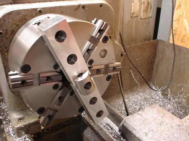
Once the halves were finished I needed to make an installation tool to mount them. Keeping them aligned to the hub is critical to ensuring the press fit goes together without galling. Starting from a piece of 3" diameter 1018, I turned off a bunch of unnecessary metal:
To create:
The tool as you can probably guess uses the hub bearings to pilot the tool and keep everything square.
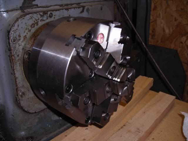
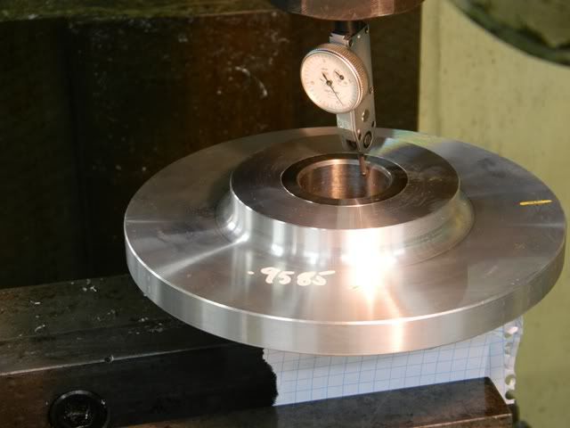
Here's a photo of the press work. In this photo I'm pressing the second pulley half onto the hub. I used a special gage pin to time the slots in the three sections together just before this photo was taken:
As expected, the bearing bore shrank by exactly .0006" on diameter. Perfect!
Since I'm a belt-and-suspenders kinda guy, 7 tons of press isn't enough! I made the decision to go one step further and use Dutch Keys to secure the halves to the hub. In this way, both friction
and the keys hold the assembly together. A Dutch Key is basically a bolt, or in this case a set screw, which is threaded into both parts at the radial parting line between them. A Dutch key transmits both torque forces and longitudinal forces between the two parts.
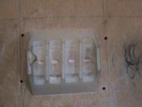
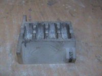
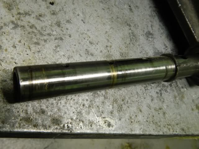
Here's a test piece which may help illustrate how it works. I'd never done a Dutch Key between such a hard and soft metal before so I did a test. It turned out a drill will wander into the soft metal when an endmill won't, so obviously I used the endmill to make the holes. The set screw shown is shorter than what I used in the actual part:
Treating the project as a bolt circle I started by finding the hub center:
Then I calculated the moves necessary to make the three holes. Here's the first one after threading:
Assembly finished! The Dutch Keys were installed until they interfered with the partial threads at the bottom of each hole and torqued to about 15 ft. lbs. As extra insurance they were assembled with blue Loctite:
A close-up of the keys:
There are a couple little details to finish up and this job can be kicked out the door (and then I can finish my set.)

Somebody is going to comment on my exponents of exponents. It's a typo and it's supposed to be scientific notation. It was 105F in the shop when I wrote that and I wasn't thinking 100% I looked at it today and had a good laugh while scanning the pages before making a bunch of scribbled corrections.


")