To avoid these ads, REGISTER NOW!

1952 Craftsman "100" DP resto

To avoid these ads, REGISTER NOW!

GirlnAgarage

Well-known member
Joined
Jan 21, 2011
Messages
4,669
Location
Texas
jtb, I've seen this thread on OWWM as well. I love it. Best piece in my book is the new head band you did with the cratex bits and valve grinding slurry. The Cman DP I just got will need this treatment as it's headband is corroded. At the very least I'm looking to take it down to fresh metal and polish.

Good score on the vari-slow attachment. The DP is came from does look half bad either.

On your other DP you restored does it have the table crank? I've read that is a fairly rare option but I'd like to hunt for one. Does Atlas make a lift crank? I thought I saw someone use an Atlas crank on their Cman DP once.

Ok, I got nothing coherent to add. Just wanted to jump in. Congrats on finding the attachment :)
 

SweetD

Well-known member
Joined
Feb 8, 2010
Messages
3,265
Location
Rhode Island
a9a69616.jpg


The attachment is in great shape and should clean up nicely.

Great score on that Vari-Slo attachment!

Can you explain how it works? I know with the "typical" speed reducer you have three sets of pulleys and you have to manually change the belt locations to change speeds...

Is there no manual changing of the belts with the Vari-Slo installed? It looks like there are a total of four sets of pulleys?

Great work - one of the best threads I've ever subscribed to!

Thanks,

Dave
 
OP
J

jtbinvalrico

Well-known member
Joined
Jan 2, 2010
Messages
1,375
Location
Tampa FL
GirlnAgarage.......Thanks for the compliment! The table lifts are rare indeed. In fact, the one I got was missing one of the miter gears and it still went for a premium. I've noticed two makes of the table lift attachment, but the units are the same and are interchangeable. I believe the one I have is by Atlas. Up to 1943, the table lift attachment in the Craftsman catalog has a widened flare to the casting on the lower column clamp where the threaded rod passes through, whereas the post-1948 units have a simpler, straight casting. I have to assume that this is attributed to a change in manufacturer. So, I have a post-1948 table lift attachment on my 1942 DP:
IMG_1327.jpg
IMG_1326.jpg

Here's the thread that details the rebuilding of that table lift:

http://www.garagejournal.com/forum/showthread.php?t=146096

Your best bet for finding these extras is in hunting complete DPs as donor machines. You can sometimes find just the attachment for sale, but in that case, a reseller is parting out the machine and probably has a pretty good idea of how rare the item is........versus an old DP someone "just wants gone" that happens to be wearing the desired attachments. In this case, my craigslist app and faithful monitoring of it finally paid off.

dave.......What they basically did was to take the two pulley system and throw two more in the middle. So, instead of swapping the belt around between the spindle and motor pulleys for various speed combinations, you leave spindle and motor pulleys alone......and the magic happens in the two middle pulleys. As you move that handle on the front face, it articulates a linkage that causes the two middle pulleys to change diameter. As one belt is tightened on a pulley, it squeezes the one next to it on the same shaft......this causes a exact, but opposite action on the other pulley set, so that moving the lever one way tightens a belt and changes the diameter for slow speed, but moving it the other way tightens the other belt and changes the diameter for higher speed. The "diameter change" is possible because both pulleys share one center plate that forms the "V" with the outer plates.......:willy_nil.........geez, I'll just work on a video of it.
 

Outlawmws

Well-known member
Joined
Aug 9, 2011
Messages
39,275
Location
The Badlands
Frank, the first belt to measure is the spindle belt, that middle cluster is on an eccentric so I'd get it slightly past center towards the spindle and measure for that belt and have the motor in the fully inbound position, then back of maybe 1/2" and measure again for the second belt.

The eccentric will of course come back a bit once its tensioned, and then the motor will take up the final slack. there should be at least a couple of inches of motor tensioning available, so while somewhat critical for belt length, the only one that is particularly close is the more limited adjustment for the first belt.

Man, table lifter and everything! That's a Home Run! :bowdown:
 
Last edited:

bluebolt

Well-known member
Joined
Dec 28, 2008
Messages
5,442
Location
Benton LA
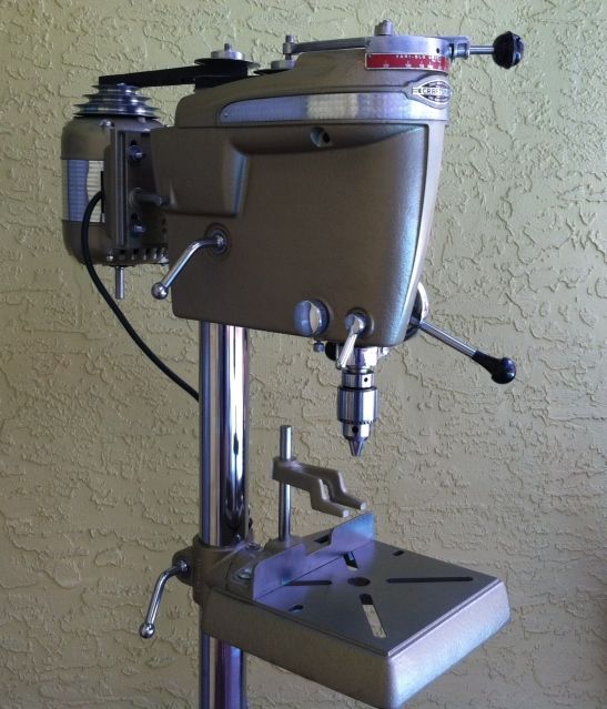
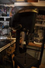
I believe the above drill press is from 1952 or 1953. The '52 and '53 catalogs are the only ones that do not show the band around the head.

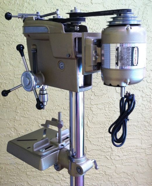
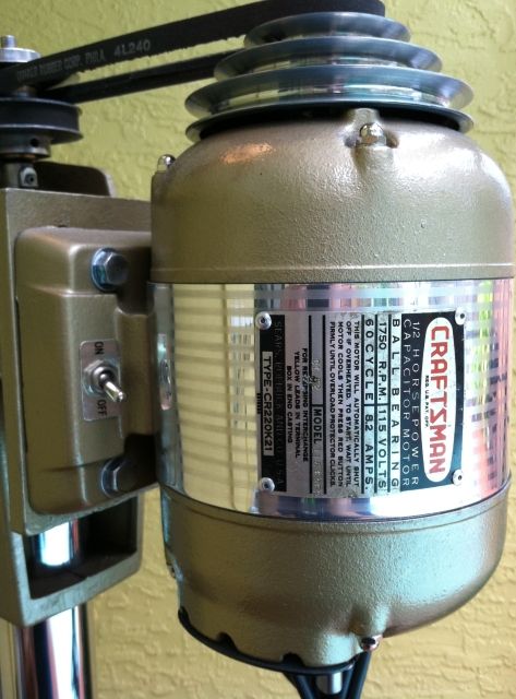
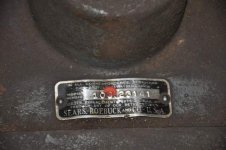
The model information label was removed from the base, so I have no idea on the exact model number or manufacturer. There may be a manufacturer number cast into the head. I need to check that out.

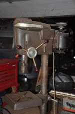
The drill press above came with several optional features:
- Production Table #99AM2306F
- Head and Table Lift #99A02419K
- Drill Press Collar #9A2429
- Slow-Speed Attachment #9A2338 (aka Multi-Speed, or Hi-Lo attachment)

Unfortunately, the slow-speed attachment was bypassed with a single belt from the motor pulley to the chuck arbor pulley.

So now I need to know what size belts to get to use the Slow-speed attachment. Does anyone have this option? I'd rather not guess, so I need the belt sizes and instruction on how to operate this feature.

7850465710_c91d1a9f54_z.jpg

FrankLee, you need a 27" and 29" belt. The longer one will go between the spindle and the multi speed pully. See this link for a picture of the original slow speed owners manual http://www.hotrodders.com/forum/homemade-low-speed-conversion-craftsman-drill-press-220616.html

And that is a nice score, I have never even heard about that big table before. and i am salivating over that table lift!
 
Last edited:
OP
J

jtbinvalrico

Well-known member
Joined
Jan 2, 2010
Messages
1,375
Location
Tampa FL
Looking good......that table is a rare piece itself. You could zap those holes with a MIG and smooth them over if you wanted.....that's what I did on my 1942.
:beer:
 

Outlawmws

Well-known member
Joined
Aug 9, 2011
Messages
39,275
Location
The Badlands
I wouldn't be too worried about those holes Frank, unless they are through and you plan on using coolant, which is what the table was deigned for. I'd bet the X-Y table of the day was intended to mount to the two factory holes that are in there.
 

woodrail

Well-known member
Joined
Feb 23, 2012
Messages
2,456
Location
Lorain, Ohio
Tonight I brought home the drill press listed on the Cleveland Ohio Craigslist for $85. I ended up paying $100 including 3 pipe clamps and 2 c-clamps!

The press need a good cleaning and adjustment. Eventually, I'd love to try a resto similar to the OPs press!

In my late night enthusiasm, I scrubbed a little to hard and faded a couple of the engine turnings on the head band! d'oh!

Here's some before pic's:
 

Attachments

  • DSC_0016.JPG
    DSC_0016.JPG
    37.3 KB · Views: 149
  • DSC_0018.JPG
    DSC_0018.JPG
    39.4 KB · Views: 141
  • DSC_0021.JPG
    DSC_0021.JPG
    18.5 KB · Views: 125
  • DSC_0027.JPG
    DSC_0027.JPG
    37.8 KB · Views: 153
  • DSC_0028.JPG
    DSC_0028.JPG
    42.4 KB · Views: 132

woodrail

Well-known member
Joined
Feb 23, 2012
Messages
2,456
Location
Lorain, Ohio
I hope posting my notes on this thread is alright, I don't intend on hijacking someone elses thread!

When I brought my DP home, the table was froze solid to the column. I soaked it with PB Blaster. Tapped on the casting a little. Soaked some more overnight without luck. This morning i removed the lock handle to the table lock. I found the plug absolutely seized to the column. I drove the plug out and the table dropped. Hey, I learned something today!

My table has a couple of quarter inch diameter holes in it, First off, how do you accidently drill through a table with a bit that size?

What method would be best for me to repair these holes? I know the OP mig welded and ground down the table. I dont weld, so I'll have to call in a favor to do this.
 
OP
J

jtbinvalrico

Well-known member
Joined
Jan 2, 2010
Messages
1,375
Location
Tampa FL
Glad to have some DP chat.....Are those holes spaced evenly like they were meant to secure something to the table? If they are close, one option is to clean them up and use them for that purpose. If you are going to farm out the repair, see if you can have someone do a cast iron welding fill on it for a proper repair.
:beer:
 
OP
J

jtbinvalrico

Well-known member
Joined
Jan 2, 2010
Messages
1,375
Location
Tampa FL
The motor band is complete. I ended up not using the lathe drum I made because I found that the means of securing the band to the drum really complicated things and I didn't want to spend even more time overcoming a hardware issue on a jig.....so I just mounted the band flat to a board and worked it from there. I started with some aluminum sheet cut to the correct dimensions, with just a bit extra to allow for smoothing the edges:

21d83430.jpg


I started with 400gr wet and worked my way through 2000gr wet, here's the progression:

a357336c.jpg


57d54faf.jpg


638ff241.jpg


This band won't come out right unless the surface is sufficiently polished, up next is the buffing wheel and some compound:

62ec5edc.jpg


ebcb61e9.jpg


f00ff978.jpg


Mirror finish after some Mother's.......ready to be selectively scuffed up:

212b3040.jpg


Here's an original band I used for reference. This one is marred after some time in a bath to remove rust, which removed the rust but left pitting. The textured lines are 1/8" across, and are 1/8" apart:

ae819eec.jpg


Hard to see in this pic (due to the glare =)........penciled lines mark off 1/8" lines on the band. I used these to guide my tape layout. The tape is laid out one stripe at a time:

2579dc56.jpg


I used 0000 steel wool wadded up in some forceps allow control. The blue tape holds up very well, allowing multiple passes to achieve a uniform scuffing to approximate the original finish. The steel wool will need to be rotated every couple of inches to allow for a proper cut on the surface:

1419dc6c.jpg


0a679c8e.jpg


d1fd8349.jpg


5b772462.jpg


Installed and ready to be put on the DP:

1c4e7906.jpg


82c5958c.jpg


Just needs a new cord and grommet. Final assembly to follow soon.
 
To avoid these ads, REGISTER NOW!
OP
J

jtbinvalrico

Well-known member
Joined
Jan 2, 2010
Messages
1,375
Location
Tampa FL
Thanks guys and girl.....

Mike, I'm parting it out for sale. You interested in any of it?
 
Last edited:

1982fxr

Well-known member
Joined
Jan 7, 2012
Messages
10,012
Location
Phoenix
you know how all the musicians in the 60's said when they saw Hendrix they decided they needed to find a new line of work? That's how i feel when I see your work! :bowdown:
 

03protege

Well-known member
Joined
Sep 13, 2012
Messages
3,104
Location
Louisiana
Wow you sir are a magician, thank you for sharing your expertise. You now have me in the mood to go polish something, but I am sure that will pass when I think about how bad my hands will be hurting 5 minutes into the project.
 

losabio

Well-known member
Joined
Jul 19, 2011
Messages
125
The idea of an "heirloom drill press" probably wouldn't have made much sense to me before seeing this thread, but I reckon that you've managed to create that very thing.
 

SweetD

Well-known member
Joined
Feb 8, 2010
Messages
3,265
Location
Rhode Island
One of, if not the, best restorations I have ever seen. Congratulations, and thanks for posting your progress from start to finish! I have the Model 150 benchtop, and this documentation will be a great source for me when I get around to fixing it up.

Now, are you going to actually use it, or is it a showpiece?

:beer:

Dave
 
OP
J

jtbinvalrico

Well-known member
Joined
Jan 2, 2010
Messages
1,375
Location
Tampa FL
It serves as my woodworking DP.....in fact, I started using it a coupla weeks ago and had to brush off the chips and dust for it's modeling debut. She's already dirty again.
:beer:
 

Rust

Banned
Joined
Nov 10, 2010
Messages
539
Location
The Path of Least Resistance
Jee whiz dude! Your diligence has really paid off. Thats Amazing.
Just think, if you get some of that sawdust in your eye you wont have to run to a mirror.
Could be a real timesaver. lol

Hey, on a rough estimate, what was the total time from start to finish? I guess the date of the first post would indicate a close proximity.
I only ask, because I was pondering how much a tool would cost, if it came from the factory like this. No one could probably afford it.
You re-set the bar quite high. You certainly have a one of a kind there. Well done.
 
OP
J

jtbinvalrico

Well-known member
Joined
Jan 2, 2010
Messages
1,375
Location
Tampa FL
If I were to do it again, I could do it in a fraction of the time. That's mainly due to the learning curves involved in parts of the process. The engine-turning is a great example. I spent far more time learning how to do it and practicing it than it actually took me to make the part. There were failures in the attempts of some processes, which I can now go straight to with success.

I could probably do it again in three weekends, if I had to guess. Learning and screwing things up along the way can easily triple that time estimate.

:beer:
 
To avoid these ads, REGISTER NOW!
Top Bottom