To avoid these ads, REGISTER NOW!

How to adjust valves on Napa Professional floor jack model# 791 6425

honda1998civic

Well-known member
Joined
Aug 4, 2011
Messages
1,581
Location
South texas
How to adjust valving on Napa Professional floor jack model# 791 6425? Recently took this hydraulic unit apart to replace seals but the valves had already been adjusted all the way down.. Can I look at another similar unit and see how far the valves are out and just set mine the same way? How are these set?
 
To avoid these ads, REGISTER NOW!

Hiball

Well-known member
Joined
Apr 30, 2009
Messages
14,027
Location
Missery
How to adjust valving on Napa Professional floor jack model# 791 6425? Recently took this hydraulic unit apart to replace seals but the valves had already been adjusted all the way down.. Can I look at another similar unit and see how far the valves are out and just set mine the same way? How are these set?

Yes... You can use another Napa Professional Jack to get the proper setting, They are very sensitive in Low/High switching valves, To Light and it wont switch to the Low side and too Heavy and you lose the Quick Lift.
 

fdny136

Member
Joined
Oct 2, 2012
Messages
10
.it has 3 valve plugs. I was rebuilding and my nephew tried helping an removed them.the jack is together and no longer leaking but I am not sure if they are set correctly.I believe I have them in there correct bore.this is actually a craftsman 2 ton aluminum.thanks
october034.jpg
 
Last edited:

Hiball

Well-known member
Joined
Apr 30, 2009
Messages
14,027
Location
Missery
.it has 3 valve plugs. I was rebuilding and my nephew tried helping an removed them.the jack is together and no longer leaking but I am not sure if they are set correctly.I believe I have them in there correct bore.this is actually a craftsman 2 ton aluminum.thanksoctober034.jpg

See post #22 and #24

The 3 Valve units are fairly simple, Working from Left to Right.. If memory serves me correctly, The First valve plug is for the High/Low Changeover. The Plug on top is Nothing more than a Screw in Cover, The Adjustment is below that Plug. The Second Valve is what i call the Working Valve, There is No adjustment Here... The 3rd Valve is the Overload, This can not be Properly Set without a Load Station. If you have adjusted this Valve, Tighten it down completely and back it off "1 and a 1/2 turns". This is just a Preliminary setting to get you close... You need to make sure that whenever you are using your jack and intend on putting yourself in harms way that you use Jack Stands and always be mindful of what your lifting. Its a Safety Device to prevent the PSI from exceeding the Limit of the Seal.

Now How to adjust... Ive already told you how to adjust the Overload (3rd), There is no adjustment on the Working Valve (2nd) So the Main Adjustment is the 1st valve with is the H/L changeover valve. You just dont want to crank it down because this Valve affects where the Oil goes when the Jack reaches its Load. If set to light you can rupture the Inner Quick Lift Cylinder by sending the High pressure oil into it versus the Big Cylinder. I used to have some starting guidlines wrote down somewhere but im misplaced them. The best way to set this jack up is by simply using a little trial and error.. What your looking for is the Jack to Operate on the High side when "No" Load is Present, But switch over to the Low end when it reaches the Load. Underneath that plug is adjusting screw with a Big spring and a Ball/Cone sitting on a Seat. You need to adjust the Spring tension till you get a Nice Crisp Transfer from High to Low. It will take a bit of Time, Just Keep track of your revolutions and make small subtle changes. Hopefully this will help.. If i can be of further assistance dont hesitate to send me a PM as i dont always see every post.
 
Last edited:

Hiball

Well-known member
Joined
Apr 30, 2009
Messages
14,027
Location
Missery
Hiball - Could we get a picture of what the load station looks like? ..just curious.

Ill try to remember to snag a picture next time im out at the shop...Really all it is is just a Steel Framed Unit (similar to a Press), at the Very top is a Cylinder that is filled with oil and at the end of that Cylinder is a Gauge that converts PSI to Tons (There is some Mathematics involved here that im not even gonna try to explain) When you load test a Jack, You simply place the Lift Arm under the Cylinder raise it against the cylinder till you get the proper reading on the Gauge, set the Overload and Retest. I have a Local Hydraulic shop here that doesnt work on Hydraulic Jacks anymore and i they take care of all the Mathematics and build these stations for me. This Setup also works very well for checking the integrity of a Hydraulic Jack and the Seals.
 
Last edited:

fdny136

Member
Joined
Oct 2, 2012
Messages
10
unfortunately my nephew removed the valves no I need to figure out where they go?
 

fdny136

Member
Joined
Oct 2, 2012
Messages
10
just like to say thanks to hiball and the other members here for all their help.my jack is together and works better then ever
 

hdrider2610

New member
Joined
Dec 31, 2012
Messages
1
does anyone have a complete schematic of this unit? I have the same jack, unfortunately i barrowed it out it came back in peices barrower tried to fix it. I have been looking to fix it for a year and this is the first site with any info on this power unit. Thank you
 

Hiball

Well-known member
Joined
Apr 30, 2009
Messages
14,027
Location
Missery

Beechbumm33

New member
Joined
Nov 10, 2019
Messages
3
Location
Hurricane, UT
I noticed you gave some advice on adjusting the valves on a napa jack. Mine is similar, except I have 4 valves. It's a 3 1/2 ton jack. Is there an extra working valve? My issue with it is once the quick lift gets a load, it trickles and doesnt like much. I removed the breather and the fluid level is full.

Any suggestions on valve adjustment or what else might be the issue?
 

Craft2ton

Member
Joined
May 7, 2020
Messages
12
Location
Nevada
Hello sir I have the same sears 3 valve unit from a Craftsman 50239 jack. I just rebuilt the unit with the kit. Everything works perfect except the speedy lift. I did remove the valves for cleaning and changed o rings. I counted the turns from bottom and reinstalled them. The high/low was 1and 1/2 turns from bottom, and the overload was 1 turn from bottom.
Center valve installed tight with no turns from bottom.
Could you please let me know what I missed or adjusted incorrectly.
Thank you, also just need a diagram to reference kit. Unusual kit came with out any instructions or even a simple diagram.
 
Last edited:

Hiball

Well-known member
Joined
Apr 30, 2009
Messages
14,027
Location
Missery
Wow.. Every “How to” on the that Website is taken from my posts here at GJ. What a piece of work.. He could have at least re-worded it.
 
To avoid these ads, REGISTER NOW!

Jeeper

Well-known member
Joined
Dec 25, 2006
Messages
2,124
Location
Round Rock, TX
Wow.. Every “How to” on the that Website is taken from my posts here at GJ. What a piece of work.. He could have at least re-worded it.

I noticed that the other day when I was on their site. They even carried the bal tech diamond balls that I asked you about years ago.

I am glad that they do have the info stored on another spot in case something were to happen to GJ. But they should at least give you credit.
 

ALTEREGO

Well-known member
Joined
May 15, 2018
Messages
420
Location
@HOME
I don't think that's right, specially when they are using someone else's expertise, that was freely given, to make money.

I believe both credit and $ are due...
 
Last edited:

Craft2ton

Member
Joined
May 7, 2020
Messages
12
Location
Nevada
All Done Craftsman 9-50239

Finally found out why the speedy lift stopped working after rebuild.
Attached are files that show my Craftsman 50239 Aluminum racing jack. This is the way I purchased this brand new, except I removed the top sticker.
By the way this jack is over 20 years old and still worked before complete rebuild. The only reason to rebuild was to bring this back to perfect condition.
The only thing the jack was doing is the main seal was making a little noise, no leaks. The problem after rebuild was a missing ball bearing on the over load valve. according to many pics and info gathered, there should only be one ball on this valve, or cone. My pic shows only one ball, 2 is needed.
But I found a small ball on the garage floor near the vise, and could not understand where it came from. So I found a pic from Omega jacks that matched my power unit. Now none of the other diagrams show this, there is actually 2 balls on the overload valve instead of one. Re inserted the valve with both balls per the omega diagram, and now the jack works better than ever.
I do not know why my valves especially, and power unit is almost exactly like the omega jacks. Anyway thanks for your concern and vast info. Almost forgot one pic shows jack height after one pump.
 

Attachments

  • CSC_0042.jpg
    CSC_0042.jpg
    108.5 KB · Views: 47
  • DSC_0037.jpg
    DSC_0037.jpg
    126.1 KB · Views: 67
  • DSC_0039.jpg
    DSC_0039.jpg
    96.6 KB · Views: 53
  • Omega Power Unit.pdf
    36.8 KB · Views: 24
  • IMG_2695.jpg
    IMG_2695.jpg
    112.7 KB · Views: 67
Last edited:

Craft2ton

Member
Joined
May 7, 2020
Messages
12
Location
Nevada
Sorry sir but not this one, please check out the Omega 26030 3 ton aluminum jack owners manual. This is exactly the same as mine. I know my pic is lousy, The only slight difference is mine has a screw instead of a clip per pic. And that's the only difference, the rest is exactly the same including, YES 2 balls on the overload.
I have torn this unit down to the bare bones. I used a Mitutoyo precision caliper to measure every ball that I removed so I can make sure of the correct placement, and crocused sealing surfaces. Also before I opened the kit I did find the missing ball on the ground. Just needed a little help as to why the Speedy lift stopped working.
I should of mentioned the one I found first. Then just pure luck would have it I remember reading you recommending Hein Werner and Omega would be good jacks to purchase. So I was looking at the Omega aluminum jacks because I must have Speedy or Magic lift along with a light unit. And the plugger release knob for the handle is a must. I could not believe it when I saw the parts break down that showed 2 balls on the overload, and the same exact diagram that my Craftsman 50239 uses. I saw this all the time as a ASE mechanic, mid production changes that drove us bonkers. Now retired I dabble. But mark my words, 2 balls on this unit. Proof is how every lifting test passes.
So your invaluable input definitely helped me out, and I thank you!
 

Attachments

  • IMG_2705.JPG
    IMG_2705.JPG
    136.8 KB · Views: 50

Hiball

Well-known member
Joined
Apr 30, 2009
Messages
14,027
Location
Missery
2 balls are required on the speed side bypass, 1 ball On the Main Cylinder Overload.

Could you insert two balls on the overload side and the Jack still function correctly? Sure, but the lower ball would have to be appropriate sized to fit the seat, and the second ball is just acting as a spacer with No place to sit. (No seat).

Omega 26030 as you mentioned.

Looking down from behind.

Left side = Overload
Middle = working valve
Right = speed bypass
 
Last edited:

Craft2ton

Member
Joined
May 7, 2020
Messages
12
Location
Nevada
Sir please look at post #6 this is what I am referring to, you say from left to right.
Man if I would have known this sooner it would of been a no brainer. I guess I was tying to adjust the overload. No wonder it took so long for me to figure out why the speedy lift was not working.
Please look at post #6 and from that view let me know if from left to right is correct ,or your last post. Thank you.
 
Last edited:

Hiball

Well-known member
Joined
Apr 30, 2009
Messages
14,027
Location
Missery
Sir please look at post #6 this is what I am referring to, you say from left to right.
Man if I would have known this sooner it would of been a no brainer. I guess I was tying to adjust the overload. No wonder it took so long for me to figure out why the speedy lift was not working.
Please look at post #6 and from that view let me know if from left to right is correct ,or your last post. Thank you.

“From Memory” was wrong on that particular model, there are multiple single pump speed lift units on the market, it’s impossible for me to remember all of them. It’s why I always recommend the owners ascertain Current settings and valve component order upon disassembly.

Sorry for any confusion.
 

Craft2ton

Member
Joined
May 7, 2020
Messages
12
Location
Nevada
I completely understand sir. I am so sorry for the mishap, Its just that I love this old jack. When I took this apart everything is so very well made, from the chrome plated fasteners to the aluminum structure. I needed to do everything I could to bring this back to life. Sorry I may have upset a few, but in the end everything worked out even better than I had expected. I think that's why these forums are so very important, from beginner to master mechanic.

Thanks again everyone for keeping me on the right path.
 

Hiball

Well-known member
Joined
Apr 30, 2009
Messages
14,027
Location
Missery
I completely understand sir. I am so sorry for the mishap, Its just that I love this old jack. When I took this apart everything is so very well made, from the chrome plated fasteners to the aluminum structure. I needed to do everything I could to bring this back to life. Sorry I may have upset a few, but in the end everything worked out even better than I had expected. I think that's why these forums are so very important, from beginner to master mechanic.

Thanks again everyone for keeping me on the right path.

No worries... Glad everything worked out.

FYI the reason Overloads only use 1 ball/cone + seat is because it’s only job is control the pressure coming from the cylinder, essentially like trying to plug the end of a water hose with your thumb. Once the pressure reaches a specific point, it will lift your thumb to release the pressure. In Valves that utilize 2 balls/seats its because they need to transfer oil, Lower ball lifts on Upstroke of pump piston, downstroke seats the lower ball and forces oil upwards that lifts the upper ball and forces oil into the main cylinder which seats the upper ball till the process is repeated.
 

lake marine

Active member
Joined
Jun 17, 2022
Messages
27
@Craft2ton and @Hiball -
I know this is an old post but I just signed up to this forum to thank you for this post as it helped me figure out why i couldn't get my "Pro Lift / Speedy Lift" G2593 to speed stroke after changing the seal kit.
I too bought the kit from hcrcnow.com and am baffled as to why they couldn't have told me or supplied me the valve adjustment instructions.
I was also baffled as to why my "kit" did not include all/or the right size seals I needed but they were good about trying to send what I needed.
Looks like a great forum...will be looking for more help on here im sure!!
Thanks...Lake
 

Lizardracing

New member
Joined
Aug 9, 2016
Messages
4
I'm resurrecting this because it applies the Craftsman #50239
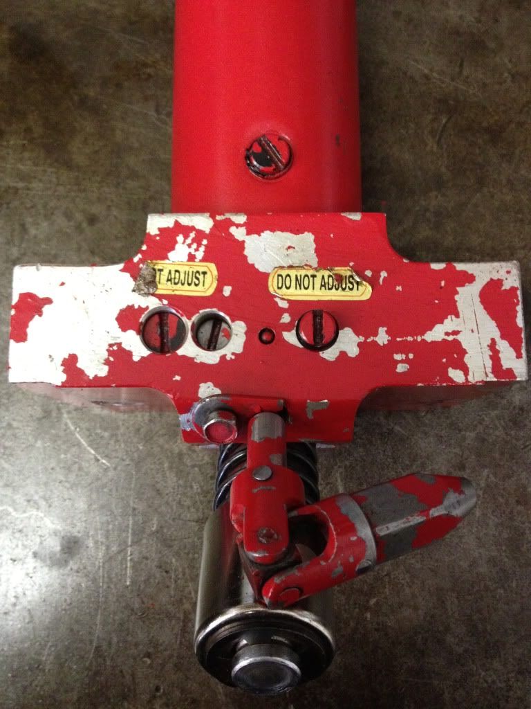
I have two of these jacks and one of them recently began to leak a little from the ram seal. (small spot on the floor when sitting unused).
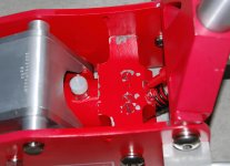
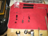
I bought this kit and disassembled, cleaned, wiped, brake clean through all passages, installed this kit
Reassembled and bled. It took a little fiddling with the H/L valve to get the switch over working so it'll lift a load.....mostly working anyway.
Before and after the reseal, this jack did something odd. When you raise the saddle one pump and then raise the handle again you have to wait 5-7 seconds before it'll raise the saddle again. The longer you wait, the more action you get. If you don't wait at all the handle does nothing. NO resistance at all. As long as wait and the longer you wait, the higher it will go on the next pump.
It acts like the plunger is taking a really long time to refill as if the fluid is too thick and moving from the reservoir to the plunger cavity very slowly. The plunger is not stuck, or sticking, I'm using ISO 32 hydraulic fluid in both jacks, and only this one does it.
Have any idea's on why its doing this?
 
Last edited:

Lizardracing

New member
Joined
Aug 9, 2016
Messages
4
Just to close this out the issue with a slow uptake was resolved with a thinner viscosity ISO22 hydraulic oil than the cheapy stuff, ISO32 I bought at the local auto parts store.
 

TonyP

New member
Joined
May 16, 2026
Messages
1
If set too light you can rupture the Inner Quick Lift Cylinder by sending the High pressure oil into it versus the Big Cylinder
I did this. I haven't pulled the jack apart yet. Does it actually rupture the cylinder, or just a seal? My jack still works, but it acts strange in that the quick lift works, but when it contacts the car it then rises and drops a little with each pump , and the next 4-5 pumps I feel a medium amount of resistance. After these 4-5 pumps it then acts normal and happily lifts the car I'm happy to use it like this, but if it's just a blown seal, I might tear it down one day. Also, is it safe to use like this? Thanks.

Edit: I think you did mean rupture. I pulled it apart today and the inner quick lift cylinder has a crease about 2 inches long that looks like it's folded in on itself. I don't think it's supposed to look like that....
 
Last edited:
To avoid these ads, REGISTER NOW!
Top Bottom