To avoid these ads, REGISTER NOW!

Show us your machining projects.

kazlx

Well-known member
Joined
Oct 30, 2012
Messages
2,851
Location
Tustin, CA
Figured I'd start a thread for maching projects.

I broke the bleeder valve off the Ramco 50 ton press I just got. Sooo, just made another one. Made it out of stainless. I think machining stainless on my lathe is one of my favorite things to do. When you get it right, it just peels off and looks beautiful. Need to make a bigger knob out of aluminum though for some leverage.

null_zps0a76635f.jpg


null_zps98133c75.jpg


null_zps5d35937f.jpg


null_zpsb67d3acc.jpg
 
To avoid these ads, REGISTER NOW!

lilredex

Well-known member
Joined
Apr 29, 2006
Messages
5,943
Location
Toronto
Made these for my old Dodge truck. When it will no longer start in "park" or the transmission linkage feels it could jump out of "park" it is time for some new (torque shaft) bushings. Most will say....just buy them...but, that's easier said than done around here.

The blanks were cut out with a hole saw, then turned on a 1/2" mandrel (bolt) to size. The slits were cut with a rod saw (blade) in a hack saw. The material was a Nylon looking sheet, donated by a friend.


program for screenshots for windows


photo hosting
 

NASTYZEN

Well-known member
Joined
Jun 11, 2010
Messages
2,823
Location
St-Colomban,Que. Canada
How about a little engraving?
Those who ski or snow board in the mountains should know this product.

The setup.
The parts get Anodized first.

imgp4943x.jpg


Part done.

imgp4948.jpg


imgp4956s.jpg


:beer:
 

Ign

Well-known member
Joined
Jul 7, 2006
Messages
12,769
Location
Butte Peak ND
Figured I'd start a thread for maching projects.

I broke the bleeder valve off the Ramco 50 ton press I just got.

Wow, looks just like the two speed box on the HF 50 ton presses. I just sent one of those boxes to the scrap yard, got tired of seeing it lying on the shop floor. Fit a different hydraulic control after the box died.
 
OP
K

kazlx

Well-known member
Joined
Oct 30, 2012
Messages
2,851
Location
Tustin, CA
Wow, looks just like the two speed box on the HF 50 ton presses. I just sent one of those boxes to the scrap yard, got tired of seeing it lying on the shop floor. Fit a different hydraulic control after the box died.

What did you put on? I don't know much about hydraulics and was wondering if I could replace it with something...
 
OP
K

kazlx

Well-known member
Joined
Oct 30, 2012
Messages
2,851
Location
Tustin, CA
Replacement bracket for a table in my dad's RV. The factory one is cast and hollow and cracked.

null_zpse5ba266a.jpg


Dimple die I made. Just CRS.

da6d4adc.jpg
 

454ragtop

Well-known member
Joined
Mar 24, 2008
Messages
5,010
Location
Carver, MA
Various parts made for the ragtop. Alt bracket and highly modified small block pulleys for the 454 FEAD. Brackets to adapt C5 Vette brakes to the Chevelle spindles. Center caps and retainers for the wheels. Love my hobby machine shop.
Jim
 

Attachments

  • 292.JPG
    292.JPG
    134.5 KB · Views: 109
  • 294.JPG
    294.JPG
    87.3 KB · Views: 85
  • 220.jpg
    220.jpg
    50.8 KB · Views: 112
  • 329.JPG
    329.JPG
    98.3 KB · Views: 89

Kevin54

MEMBER EMERITUS
Joined
Jan 12, 2005
Messages
29,341
Location
Urbana, Ohio
These are some of the tools I made when I worked at the shop. Some is showing some wear as far as stains, but these tools are also close to thirty years old. I always figured, why buy when you can make them cheaper. The angle plate is the very first thing I made back in 1981 when I started, and it has held it's squareness within .0001 in all of those years. The Sine plate was the second tool I made. I actually made two Sine plates and they would bolt together to make a Compound Sine Plate, but a friend that worked in the department needed a Sine Plate, so I gave one to him. The very last thing I made in the shop was two years ago, and it is the wide 5" Sine Bar. Dead nuts on the money. The other pics are just some Vee Blocks, Cylindrical Square, smaller Sine Bars, Angles in 45 degrees and 30-60-90 degrees, then a set of angles from 1 degree thru 4 degrees and then a 5 and 10 degree angle to make a set. I've probably more items but that was just a few pics right off I had in an album.


79720246.jpg

83904815.jpg

85145485.jpg

58746494.jpg

72791665.jpg

40287659.jpg

93962295.jpg

60796619.jpg

61075507.jpg

83770661.jpg

31398466.jpg
 

mrpowderkeg

Well-known member
Joined
Dec 9, 2008
Messages
776
Location
Bismarck North Dakota
I made a quick and dirty vacuum T on my lathe, I was in a hurry, heck the ribs were not even equal in number on each side. It just needed to not come off and hold boost pressure. I love and hate this T now, it doesn't leak and a hose will not come off, but when you need to remove a hose from it, you have to cut the hose off...
 

Attachments

  • vacuumt.jpg
    vacuumt.jpg
    62.9 KB · Views: 205

NASTYZEN

Well-known member
Joined
Jun 11, 2010
Messages
2,823
Location
St-Colomban,Que. Canada
I made a quick and dirty vacuum T on my lathe, I was in a hurry, heck the ribs were not even equal in number on each side. It just needed to not come off and hold boost pressure. I love and hate this T now, it doesn't leak and a hose will not come off, but when you need to remove a hose from it, you have to cut the hose off...

Wow. This thread is starting off well. Nice work guys.:thumbup:

How did you weld up the fitting? Looks almost fused.
 

mrpowderkeg

Well-known member
Joined
Dec 9, 2008
Messages
776
Location
Bismarck North Dakota
Wow. This thread is starting off well. Nice work guys.:thumbup:

How did you weld up the fitting? Looks almost fused.

I began by drilling each part on the lathe, on the longer part of the T, I made sure to leave enough metal in the middle for welding, and at the end of the short part I did not drill all the way through. Then I welded the two pieces with my tig welder, and then finished drilling the holes with a hand drill
 

Attachments

  • vacuumt2.jpg
    vacuumt2.jpg
    74.4 KB · Views: 82

mrpowderkeg

Well-known member
Joined
Dec 9, 2008
Messages
776
Location
Bismarck North Dakota
I made some spacers for adapting 8.8 inch disc brakes to a small bearing late 50s ford 9". The centering hub needed a spacer, as well as the axle bearing because of how the backing plate setup is different from the old drum to the newer disc setup.

I turned these spaces from 1/2 inch plate, I could not find a thick washer to turn down to work, so solid stock had to be machined
IMG00244-20101219-1401_zps5bfa1ed8.jpg


02abbe8f-ea04-4f8a-8c7c-99cd82fe47d7_zps64988e8e.jpg


The disc for the 8.8 had a larger centering hole so I had to make some spacers for that as well

IMG00249-20101219-2308_zpsf0abb54c.jpg


And just a quick check as to how everything centered up, the rotor is not all the way seated in the pic but it does fit perfectly

IMG00250-20101219-2317_zps7f1599bf.jpg
 

Kevin54

MEMBER EMERITUS
Joined
Jan 12, 2005
Messages
29,341
Location
Urbana, Ohio
This isn't mine, although I wish I could take credit for it. This thing is just the shits though. If you can, magnify the picture and look at the detail. It states that it is a Miller Welding project, but I don't know whether it is a collaboration of all of the students, or one individual. I've worked on projects at work that took awhile to finish. Heck, to me a month seems like a long time. But something like this had to take a few years to do. If anyone know anything about it, please post it up. I was going to start another separate thread but since this is machining projects, I figured I'd toss it in here. Look at it close as there are a lot of people standing in it. A welder or two, Oxy/Acet outfit, and Lord knows what everything else is.

4525609183_df6867bd75_o.jpg
 

Kevin54

MEMBER EMERITUS
Joined
Jan 12, 2005
Messages
29,341
Location
Urbana, Ohio
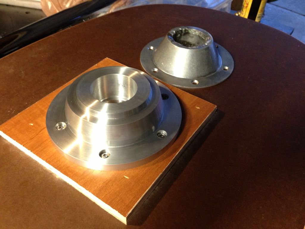
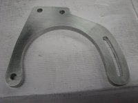
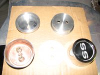
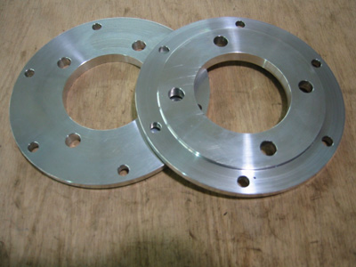
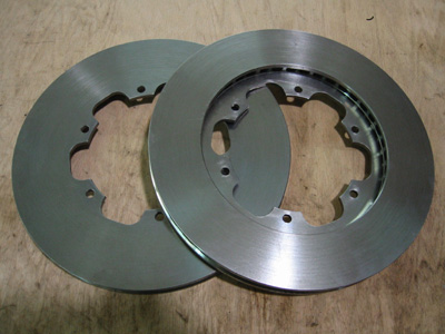
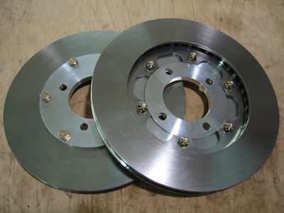
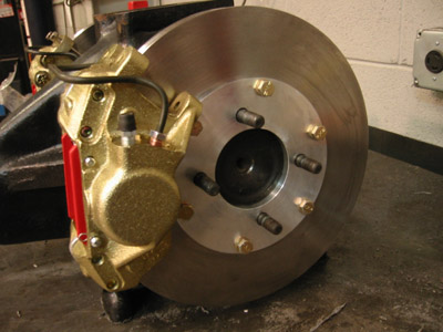
Now these are my projects. The first one is a pair of Rotor Hats. One set for a member on here and another set for a friend of his. 7075 aluminum, which I really like the machining properties of.

dscf1489c.jpg


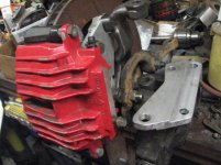
This is just one of the many reflectors that we made at work. I made the tooling, then had to prove out the reflector. This ine hasn't been chem polished or anodized yet

dscf1251r.jpg


This is another reflector prototype that I made. When it went into production it was made of of a cast aluminum. That was one good thing about working in the Toolroom and Model Shop......we got to work on the parts first.

dscf1268g.jpg


This was some stainless steel latches I made for some light on a Boeing aircraft.

dscf1273e.jpg


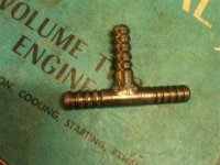
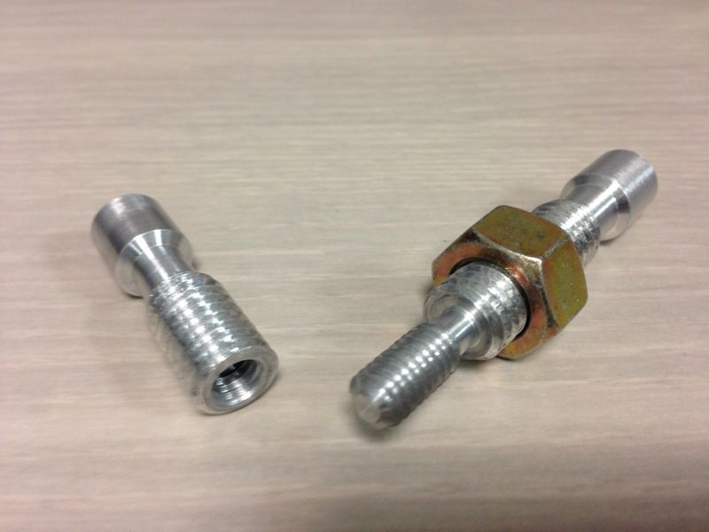
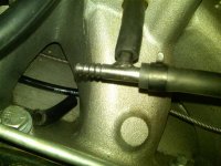
This is a quick adjusting riser block. You pull the "C" clip out, slide the inner part up or down, slip the "C" clip back in, then the screw adjustment is on top

dscf1266n.jpg

dscf1265v.jpg


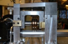
This is an aluminum handle, or the start of an aluminum handle. It goes on a searchlight for a helicopter. The handle eventually gets knurled and welded on. If anyone has ever bent aluminum tubing in a bender, you will know that the pipe will deform some in the bend and become egg shaped. This pipe had to maintain it roundness within .005 throughout the length of the tube. This tube has already been cut to length on the short end. When I made the tooling, then formed the tube, the tube was within .002 throughout the entire length. How I did it was by using two blocks of O-1 Tool steel. In each half of the blocks, I made a groove through the blocks at .500 deep x .500 radius. The tube diameter is 1.000". The two halves were doweled together and clamped. Using some grease for lubrication purposes, I then use a hydraulic press and pushed the tube down through the blocks. The size of the grooves through the block kept the diameter of the tube in check, and the result was a wrinkle free, non egg-shaped tube, bent at the correct angle each and every time.

dscf1237.jpg


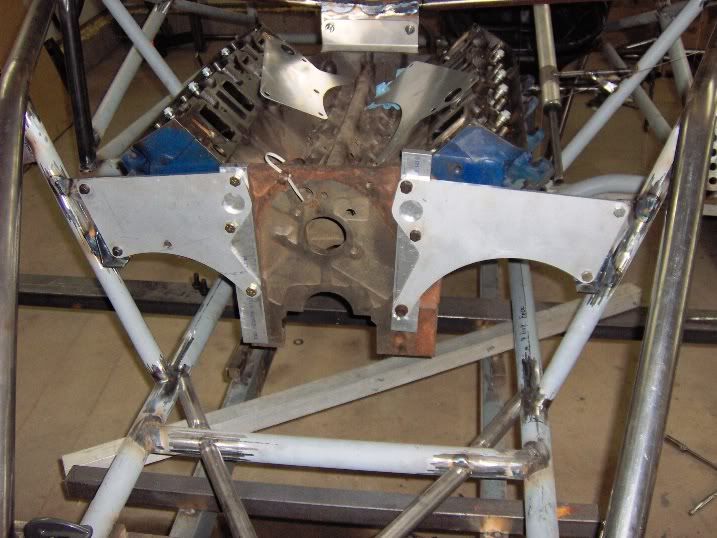
The last picture, you guys can take a guess on it. Every single surface is machined on a compound angle. The tolerances on the part were +/-.002 everywhere, and is dead nuts on.

dscf4856s.jpg


dscf4855l.jpg


I've made so many precision tools for work as I showed above in my previous post, such as the angle plates, Sine plates, vises, and so on. I've made thousands of rivet punches for Universal head rivets. My wife has some of those still. Then a lot of smaller personal tools like boring bars, fly cutters, saw arbors, vise stops, and the list goes on and on. Eventually, I hope to get some equipment for home so that I can make a few things when I feel up to it. I got a lead on a 2 axis CNC mill, so I'm keeping my fingers crossed on that.
 

Graham08

Well-known member
Joined
Dec 10, 2007
Messages
713
Location
Iron Station, NC
Here is one of my most recent projects, a set of steering arms for a supermodified.

Starting block of 6061, and after the 1st vise setup:


2nd vise setup, radiusing the top of the mounting lugs:


After the 2nd vise setup, with mounting lugs and the tie rod hole:


After two rotary table setups to get the final shape:


Installed on the spindle:


I also made the caliper brackets for this, but that wasn't nearly as involved.
 
To avoid these ads, REGISTER NOW!

pepi

Well-known member
Joined
Mar 27, 2013
Messages
2,883
Location
Woodstock, GA
Man I'm liking the front end parts, they are alum? Not knocking just asking, the Heim joint. It may be the picture and unable see the true scale, but they look thin. For a part that takes a good whack and substantial stress on occasions. SMs are prone to some crazy race action, the grade 8 hardware will handle it.
 

Kevin54

MEMBER EMERITUS
Joined
Jan 12, 2005
Messages
29,341
Location
Urbana, Ohio
Kevin, What was the application for those rotor hats? Looks similar to a project on my to-do list. Keith

You need to ask Fastkat that is a member on the site. He can explain it way better than I can. I understand them sorta, but I haven't seen them mounted up, so not really sure. :headscrat

Fastkat will explain it all to you.
 

Graham08

Well-known member
Joined
Dec 10, 2007
Messages
713
Location
Iron Station, NC
Badass. How did you radius the lugs in this pic?

Thanks.

One name for it is "Kellering"...basically take a number of steps over and down using a ball end mill to approximate the radius. Then clean up with a file. It's basically the same way a CNC would cut this sort of a profile without a 4th or 5th axis.

Here's a link to Tom Lipton's blog. He explains it much better.

http://oxtool.blogspot.com/2013/04/pot-metal-prosthetic.html
 

Graham08

Well-known member
Joined
Dec 10, 2007
Messages
713
Location
Iron Station, NC
Man I'm liking the front end parts, they are alum? Not knocking just asking, the Heim joint. It may be the picture and unable see the true scale, but they look thin. For a part that takes a good whack and substantial stress on occasions. SMs are prone to some crazy race action, the grade 8 hardware will handle it.

Thanks. The Heim joints are 1/2" x 5/8", alloy steel, so they're pretty beefy. Generally these don't break without hitting something pretty solid.
 

Kevin54

MEMBER EMERITUS
Joined
Jan 12, 2005
Messages
29,341
Location
Urbana, Ohio
You use a DRO or no? I need to learn that. I'm still pretty fresh with the mill.

You don't necessarily HAVE to use a ballnose end mill. If you have never done that before, and if you have a compass, scribe out your radius and using a standard flat bottom end mill, cut to the radius in increments. This is the way we used to make balls in a lathe for punches. It's easiest if you pick either the "Z" axis, or the "X" axis to use a common movement. For example.....You have a 2" block and want to put a 1" radius on the upper L.H. corner. Start with your end mill set at "Z" zero at the top of your part. Using only the "Z" axis raise the table in .050 increments, while you move your cutter into the scribed radius line in the "X" dimension.

If you are good with math you can figure up your points along the "X" axis radius at different intervals. Other than that, if you have good eyes, cut to the scribed line. Once you have your cuts made, you will now have steps. Then take a large sharpie and color in the ledges that you have cut into the part. You start filing until the black lines disappear. If you would like, I could go into a little more detail. The blue vertical lines showing, would be the edge of your end mill. If you can visualize it on the sketch, you can see the small triangles that would be left standing proud. Once you start filing it down, you will see how that everything that is covered with the sharpie is making lines smaller and smaller. Once you get down to where the lines are about the thickness of a hair, you cab really see where you need to file harder or not file as hard. We made punches in the lathe like that also. Although if doing a round piece in a lathe, or an odd radius, you need both coordinates, "X" & "Z". We've made some real close precision parts using this method.

In a mill, and even in a lathe, the reason that you want to use one standard coordinate is so you don't lose yourself where you're at in cutting the part. If you have a simple CAD program (I use DeltaCad), you can pick both coordinates and cut to those. The smaller the standard coordinate, the less filing, but also the more cutting. By smaller, I mean using a standard coordinate like .025 in lieu of .050.

attachment.php
 

Attachments

  • stepped.JPG
    stepped.JPG
    40.6 KB · Views: 1,495

Graham08

Well-known member
Joined
Dec 10, 2007
Messages
713
Location
Iron Station, NC
You don't necessarily HAVE to use a ballnose end mill.

Right. I think the ball mill makes for a little less filing in the end.

In my case, my step in y was 1/16" until I got toward the edge of the part and the depth of cut got pretty deep. When that happened, I reduced the step to 1/32". Had I been thinking I would have used 0.050" and 0.025" because they're nice round numbers on the dials.

This was my first stab at this, so there are definitely some things I would do differently in the future.
 

Kevin54

MEMBER EMERITUS
Joined
Jan 12, 2005
Messages
29,341
Location
Urbana, Ohio
Right. I think the ball mill makes for a little less filing in the end.

In my case, my step in y was 1/16" until I got toward the edge of the part and the depth of cut got pretty deep. When that happened, I reduced the step to 1/32". Had I been thinking I would have used 0.050" and 0.025" because they're nice round numbers on the dials.

This was my first stab at this, so there are definitely some things I would do differently in the future.

That's true, it does make for less filing. In my case though, we had to have punches within .005, so with the way the Engineers would give us the "X" / "Y" coordinates, we had to use a sharp tool to cut the parts. That way, we would have a very sharp crisp line when we were close. If we used a ball nose end mill, there would have been way too much calculating because the center of the radius changes in every "X" or "Z" move. That's one nice thing about CNC's with the "Z" axis computer controlled. If you have the right program, it automatically figures in the compensation for using a ball nose. :beer:
 

FastKat

Well-known member
Joined
Jan 4, 2010
Messages
553
Those are a set of rotor hats for a Jaguar rear suspension with inboard brakes. I have some pictures - I'll let them do the explaining!

IMG_5638smallest.jpg


IMG_5639smallest.jpg


IMG_5642smallest.jpg


IMG_5682smallest.jpg


IMG_5673smallest.jpg


IMG_5684smallest.jpg


IMG_5696smallest.jpg


The original setup had solid rear rotors, which suffered from heat-related problems. I had a set of custom vented rotors made and used the hats to mount them to the stub axles. This setup runs cooler. The parts came out great - thanks Kevin! There were a few little things I forgot to put in the drawing, but it's all together now and I couldn't be happier.

You need to ask Fastkat that is a member on the site. He can explain it way better than I can. I understand them sorta, but I haven't seen them mounted up, so not really sure. :headscrat

Fastkat will explain it all to you.
 

Gary Anderson

Active member
Joined
Jun 2, 2011
Messages
32
Location
Rosemount MN
11 (Medium).jpg

10 (Medium).jpg

9 (Medium).jpg

7 (Medium).jpg

3 (Medium).jpg

2 (Medium).jpg

Some of the things my oldest son does, gun barrel vise, controller for his trailer, Stanley Cup Championship Ring.
He does the World Series and Super Bowl ones too.
He does the ring stuff at his work.
That is him in the avatar, working in my garage.

Your Pal, Gary
 
Last edited:

KMScott

Well-known member
Joined
Feb 14, 2012
Messages
4,632
Location
Daufuskie Island, South Carolina
Just finished this custom pipe cutter. I was asked to design and build this cutter to cut the aluminum tubing used in copier machines that transfers the image to paper. They were cutting samples with a band saw and the heat was melting the coating. That is why they wanted this pipe cutter. Built this in my home shop. I do not own a lathe and have to rent one but having a surface grinder and a CNC goes far along with a Suburban Tool Master spin fixture for grinding in the special arbors used to support the tubing. I paid a CNC lathe guy to build the H-13 cutters.

I am teaching my son this dying trade and he is really enjoying building another fixture not as complicated as this one. My day job I work as a internet marketer and this is what I do at nights.

Kevin
 

Attachments

  • Slitter for Alan Campbell (1).jpg
    Slitter for Alan Campbell (1).jpg
    139.4 KB · Views: 245
  • Slitter for Alan Campbell (2).jpg
    Slitter for Alan Campbell (2).jpg
    130.2 KB · Views: 206
  • Slitter for Alan Campbell (3).jpg
    Slitter for Alan Campbell (3).jpg
    142.4 KB · Views: 195
  • Slitter for Alan Campbell (5).jpg
    Slitter for Alan Campbell (5).jpg
    143 KB · Views: 177
  • Slitter for Alan Campbell (6).jpg
    Slitter for Alan Campbell (6).jpg
    137 KB · Views: 167

bobadame

Well-known member
Joined
Dec 26, 2007
Messages
1,124
Really nice work there Kevin. That's a beautiful piece and cool that your teaching your son.
 
To avoid these ads, REGISTER NOW!
Top Bottom