To avoid these ads, REGISTER NOW!

What Does This Do?

jims09build

Well-known member
Joined
Nov 11, 2009
Messages
102
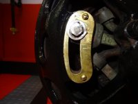
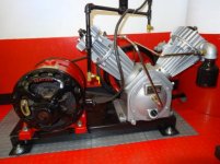
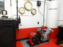
All you electric motor experts should know what this does on this old Century 2 HP motor. (First Picture) I don't have a clue.:headscrat I've had it on my Ingersoll-Rand Type 30 compressor for over 40 years and it has run faithfully all this time. I just restored the compressor and cleaned up the motor and painted it which brought up this question. I have never changed the setting from where it is now. I added a couple pics of my setup.

Thanks,

Jim
 

Attachments

  • IR Compressor 11-2-12 008.jpg
    IR Compressor 11-2-12 008.jpg
    137.6 KB · Views: 228
  • IR Compressor 11-2-12 007.jpg
    IR Compressor 11-2-12 007.jpg
    42.9 KB · Views: 212
  • IR Compressor 11-2-12 001.jpg
    IR Compressor 11-2-12 001.jpg
    34.9 KB · Views: 198
To avoid these ads, REGISTER NOW!

drcliff

Banned
Joined
Jan 2, 2011
Messages
16
That's an adjustment for the motor's starting circuit. Before cap-start motors, some motors had basically an extra set of brushes that only worked when the motor was starting up. This (sort of) doubled the starting torque. It's set at the factory and then never again, I think. On your motor you can swing the start brushes far enough to make the motor start & run in either direction.
 
OP
J

jims09build

Well-known member
Joined
Nov 11, 2009
Messages
102
That's an adjustment for the motor's starting circuit. Before cap-start motors, some motors had basically an extra set of brushes that only worked when the motor was starting up. This (sort of) doubled the starting torque. It's set at the factory and then never again, I think. On your motor you can swing the start brushes far enough to make the motor start & run in either direction.

Thanks for the reply. I've always enjoyed watching those extra brushes kick in and love the sound it makes. Do you think mine is adjusted to maximum torque?
Since I put new rings in the compressor it seems to struggle a little sometimes when starting.

Thanks,

Jim
 

scw1991

Well-known member
Joined
Mar 28, 2010
Messages
506
Actually, this changes the motor shaft rotation on a repulsion induction motor . By loosening the bolt, you can rotate the brush assembly to either position "R" or "L". In today's terms it's either CW (clockwise) or CWW (counterclockwise)
 
OP
J

jims09build

Well-known member
Joined
Nov 11, 2009
Messages
102
Actually, this changes the motor shaft rotation on a repulsion induction motor . By loosening the bolt, you can rotate the brush assembly to either position "R" or "L". In today's terms it's either CW (clockwise) or CWW (counterclockwise)

Thanks for the explaination.
 
To avoid these ads, REGISTER NOW!

signcrafter

Well-known member
Joined
May 9, 2012
Messages
12,360
That is really nice! What are those 3 beautiful pressure gauges for on the wall? I see one comes off the air lines but the other two are at different pressures?

If the rest of the shop looks like that I think we are going to need a full shop tour picture thread!
 
OP
J

jims09build

Well-known member
Joined
Nov 11, 2009
Messages
102
Can any of you AIR experts figure how much cfm this unit is capable of with this information?

Motor is 2hp
RPM is 1165
Motor sheave 6" dia
Compressor sheave is 18" dia
1st stage bore is 4"
2ND stage bore is 1-1/2"
Stroke is 3-1/2"
Inlet size is 1-1/4"
Outlet size is 3/8" pipe size

I'm running it set @100# on to 125# off. Takes 3 minutes to do this.

Thanks,

Jim
 
OP
J

jims09build

Well-known member
Joined
Nov 11, 2009
Messages
102
That is really nice! What are those 3 beautiful pressure gauges for on the wall? I see one comes off the air lines but the other two are at different pressures?

If the rest of the shop looks like that I think we are going to need a full shop tour picture thread!

The 3 gauges are old Ashcroft gauges that came out of an old nat. gas compressor station about 40 years ago. The last test is written inside dated 1961. The faces screw off and they are solid brass. I've had them stored for 40 years. 1 is for tank pressure, 1 is for regulated pressure and the 3rd is the pressure going to my other garage about 80 feet away. I have a leak somewhere in the line going to the other garage and had the valve shut off so thats why the pressure difference.

I would be happy to show the rest of the place once I get it cleaned up. It's a pretty nice place to keep my 65 Shelby Cobra Replica I built and painted using this same compressor.

Jim in Pa 23 degrees this morning, brrrrr

Jim
 

Jtcrep

Well-known member
Joined
Apr 20, 2013
Messages
80
Can any of you AIR experts figure how much cfm this unit is capable of with this information?

Motor is 2hp
RPM is 1165
Motor sheave 6" dia
Compressor sheave is 18" dia
1st stage bore is 4"
2ND stage bore is 1-1/2"
Stroke is 3-1/2"
Inlet size is 1-1/4"
Outlet size is 3/8" pipe size

I'm running it set @100# on to 125# off. Takes 3 minutes to do this.

Thanks,

Jim

You need to know your tank size. I used CFM Calculator from the google play store on my android phone. For a reference my T30 model 253 made 17.71 cfm when starting at zero and going to 125psi in 7minutes 42 seconds. I haven't calculated the cfm in a working environment yet.
 
OP
J

jims09build

Well-known member
Joined
Nov 11, 2009
Messages
102
You need to know your tank size. I used CFM Calculator from the google play store on my android phone. For a reference my T30 model 253 made 17.71 cfm when starting at zero and going to 125psi in 7minutes 42 seconds. I haven't calculated the cfm in a working environment yet.

Tank is 80 gallon.

Thanks,

Jim
 
To avoid these ads, REGISTER NOW!
Top Bottom