Mystic_Cobra
Well-known member
I'm insulating and wiring my 2-car attached garage. House built in '65. I'm planning to do all the work myself. The ceiling is sheetrocked. The walls are concrete block. The attic above is accessible via pull down stairs. Attic will get new insulation after I'm done. I'm adding a few exterior lights during this project (garage door side and front sidewalk) and adding cabinets (leftover from Kitchen redo) as well. The panel was recently replaced, is in the garage, and is 200A with at least (one installed isn't used) 12 slots free.
Here's a 3D sketchup:

Here's what one framed wall looks like. Note the exterior man door and electric panel.

Primary purpose of garage is for car work of all kinds. I own three Mustangs (one road race car, one '65 street car, one '94 DD.) Again, I do everything myself.
I just finished the framing and I'm getting ready to start the electrical.

I've read a bunch on here so I am planning to put the outlets at 52". The existing (green dots) ceiling lights are standard single bulb CFLs on 3-way switches at the two man doors. I was planning to leave these as-is. Suggestions? They share a circuit with other things in the house. One switch is just inside the exterior door at left and the other is inside the living room at bottom.
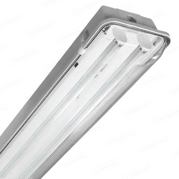
I'm planning to put a bank of three switches just left of the living room man door on the chimney to control the 15 ceiling 4' twin-tubes (yellow rectangles) on a new 15A circuit.
The receptacles would be on two 20A circuits (one existing, one new). I'm still contemplating how many receptacles will be double duplex or single duplex. How many is too many? I have three now on the one existing circuit.
I'm changing from old-school garage doors with horizontal springs and chain drives to ALL NEW torsion spring doors with jack shaft openers (later). Wiring to be done now, doors will come later in the year. One new 15A circuit for these.
I'm planning to put some outlets inside the cabinets so I can run LED strip lighting on the toe kicks for some "under-car" lighting.
I spend most of my time in the lower right quadrant of this garage near the utility sink. The racecar lives on this side and gets more attention than my other Mustangs, the truck, trailer, and the wife's car combined.
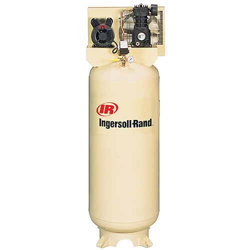
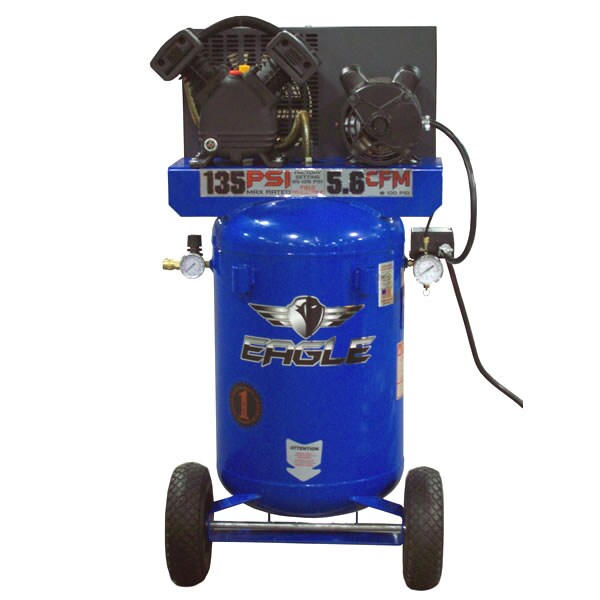
Air compressor is a horizontal 110V Craftsman and will likely go under a custom cabinet. Also, in the plan but not on the drawings, is a mini-split AC/heat pump that will go over the exterior man door. Receptacle is on the drawing.
Here's a 3D sketchup:
Here's what one framed wall looks like. Note the exterior man door and electric panel.
Primary purpose of garage is for car work of all kinds. I own three Mustangs (one road race car, one '65 street car, one '94 DD.) Again, I do everything myself.
I just finished the framing and I'm getting ready to start the electrical.
I've read a bunch on here so I am planning to put the outlets at 52". The existing (green dots) ceiling lights are standard single bulb CFLs on 3-way switches at the two man doors. I was planning to leave these as-is. Suggestions? They share a circuit with other things in the house. One switch is just inside the exterior door at left and the other is inside the living room at bottom.
I'm planning to put a bank of three switches just left of the living room man door on the chimney to control the 15 ceiling 4' twin-tubes (yellow rectangles) on a new 15A circuit.
The receptacles would be on two 20A circuits (one existing, one new). I'm still contemplating how many receptacles will be double duplex or single duplex. How many is too many? I have three now on the one existing circuit.
I'm changing from old-school garage doors with horizontal springs and chain drives to ALL NEW torsion spring doors with jack shaft openers (later). Wiring to be done now, doors will come later in the year. One new 15A circuit for these.
I'm planning to put some outlets inside the cabinets so I can run LED strip lighting on the toe kicks for some "under-car" lighting.
I spend most of my time in the lower right quadrant of this garage near the utility sink. The racecar lives on this side and gets more attention than my other Mustangs, the truck, trailer, and the wife's car combined.
Air compressor is a horizontal 110V Craftsman and will likely go under a custom cabinet. Also, in the plan but not on the drawings, is a mini-split AC/heat pump that will go over the exterior man door. Receptacle is on the drawing.
Last edited: