To avoid these ads, REGISTER NOW!

Does outlet next to panel have to be its own, dedicated circuit?

Quijote

Well-known member
Joined
Feb 27, 2013
Messages
179
Location
Greater Boston
I was planning on leaving it alone (it was installed by electrician that ran underground power to garage), but my neighbor (electrician who pulled permit for me) rolled his eyes and said I should just tie the next several outlets to that circuit.

I don't see what the big deal is, but he feels pretty strongly about it. I rather leave it alone (it has a short 12-2 run and a 15A GFCI outlet) and have my 20A circuit (with it's own 20A GFCI outlet) separately.

It's almost more work to do it his way.

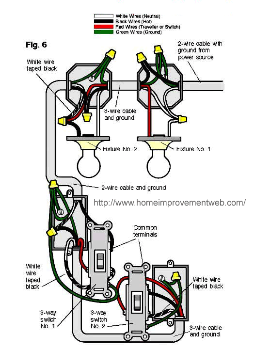
He also spent 15 minutes arguing with me that doing what's shown below was wrong - even as I am showing him the image below printed in color and telling him all the wiring was already done. Eventually he said he had never done it that way but "I guess it works."
wiring6l.gif
 
To avoid these ads, REGISTER NOW!

Charles (in GA)

Well-known member
Joined
Jan 11, 2006
Messages
12,489
Location
50 mi south of Atlanta
With some things, there is more than one way to "skin a cat". As far at the diagram above, that is perfectly fine. Not sure what his issue is. Was it with the white wires being taped black? or with the use of the red wire? Biggest problem NOW is that the illustration you show does not have a neutral at the switches, it stops at the fixtures, which is fine, and workable, but current NEC (2014) now requires a neutral in every switch box, due to the proliferation of electronic light controllers and timers, which need the neutral to function. So even if you are using standard snap switches, you are supposed to carry the neutral to the box and cap it off, so its there if needed.

As far at the number of circuits, again, what does it matter? Your electrician is in the businessman mentality of saving money by using less breakers and less wire. Fact is, the breaker is about $4 including tax at Home Depot, and the wire is already there. Nothing worth saving is really being accomplished by doing it his way. Having extra circuits is good, you can work on one, replacing a receptacle or whatever, without killing everything in the shop, leaving you one for a work light, drill, etc.

I would just tell him if its a money issue, you don't care if you spend a couple of bucks extra, and if its a code issue, to say so, otherwise you are just going to run the additional circuit and keep on.

If tries to tell you its a code issue because its a "single" 15 amp GFCI on a 12 gauge wire and 20 amp breaker, politely remind him to look at the definition of single and multiple receptacles and the table located at 210.21(B)(3) in the code. Your duplex receptacle counts as TWO receptacles and is acceptable by code to be installed on a 20 amp circuit by itself.

Charles
 
OP
Q

Quijote

Well-known member
Joined
Feb 27, 2013
Messages
179
Location
Greater Boston
That's what I figured, thanks. He just didn't seem to get why putting both switches at the end. He said I was using 14-3 needlessly when 14-2 would have done the job between fixtures if wired differently.

I do know about the grounding. This is all for the rough-in, so nothing's been connected to devices yet.
 
Last edited:

Mustang51js

Well-known member
Joined
Jan 24, 2014
Messages
1,734
Location
Haskell nj
Well in a way you are wasting money using the three wire through the lights instead of just running a two wire to one switch. The other thing is he prob figures your never going to max out that circuit as a single outlet. I'm sure if you start filling up the panel you will end up putting that outlet on with something else later. But overall I don't see anything wrong. Grounding needs to be connected and crimped together for inspection, if metal boxes are used they need a green ground screw also for inspection.
 

Cmreschke

Well-known member
Joined
Feb 15, 2014
Messages
775
Location
North of Detroit
^ debatable, it all depends on the switch location in relation to the panel. If the switch is closer to the panel than the light then yes I agree, but if the lights are closer than the switch is, well he's possibly cheaper this way.
 
To avoid these ads, REGISTER NOW!

sberry

Banned
Joined
Jun 18, 2005
Messages
35,747
Location
Brethren, Michigan
While I will be the first to argue agasinst cost and waste and preparing for load that never comes I am also a fan of having a single device circuit available. If you need the space use it, if not and its easier to go to the panel by all means leave the thing. Ever want to connect motor temp motor load or turn off other circuits can hang a light yet. You might want to extend it later as an outlet circuit.

As far at the number of circuits, again, what does it matter? Your electrician is in the businessman mentality of saving money by using less breakers and less wire. Fact is, the breaker is about $4 including tax at Home Depot, and the wire is already there. Nothing worth saving is really being accomplished by doing it his way. Having extra circuits is good, you can work on one, replacing a receptacle or whatever, without killing everything in the shop, leaving you one for a work light, drill, etc.
Yes,,, I respond then read thread.
 
Last edited:

TheEquineFencer

Well-known member
Joined
Jan 15, 2009
Messages
9,278
Location
Farmville, NC 27828
With some things, there is more than one way to "skin a cat". As far at the diagram above, that is perfectly fine. Not sure what his issue is. Was it with the white wires being taped black? or with the use of the red wire? Biggest problem NOW is that the illustration you show does not have a neutral at the switches, it stops at the fixtures, which is fine, and workable, but current NEC (2014) now requires a neutral in every switch box, due to the proliferation of electronic light controllers and timers, which need the neutral to function. So even if you are using standard snap switches, you are supposed to carry the neutral to the box and cap it off, so its there if needed.

As far at the number of circuits, again, what does it matter? Your electrician is in the businessman mentality of saving money by using less breakers and less wire. Fact is, the breaker is about $4 including tax at Home Depot, and the wire is already there. Nothing worth saving is really being accomplished by doing it his way. Having extra circuits is good, you can work on one, replacing a receptacle or whatever, without killing everything in the shop, leaving you one for a work light, drill, etc.

I would just tell him if its a money issue, you don't care if you spend a couple of bucks extra, and if its a code issue, to say so, otherwise you are just going to run the additional circuit and keep on.

If tries to tell you its a code issue because its a "single" 15 amp GFCI on a 12 gauge wire and 20 amp breaker, politely remind him to look at the definition of single and multiple receptacles and the table located at 210.21(B)(3) in the code. Your duplex receptacle counts as TWO receptacles and is acceptable by code to be installed on a 20 amp circuit by itself.

Charles

I'm not doubting what you are saying about "current NEC (2014) now requires a neutral in every switch box, due to the proliferation of electronic light controllers and timers, which need the neutral to function. So even if you are using standard snap switches, you are supposed to carry the neutral to the box and cap it off, so its there if needed." Can you give me the code section for that? PM or post, either one.
 

Stuff

Well-known member
Joined
Aug 31, 2013
Messages
572
New in 2011 - section 404
(C) Switches Controlling Lighting Loads. Where switches
control lighting loads supplied by a grounded general purpose
branch circuit, the grounded circuit conductor for the controlled
lighting circuit shall be provided at the switch location.

Exception: The grounded circuit conductor shall be permitted
to be omitted from the switch enclosure where either
of the following conditions in (1) or (2) apply:

(1) Conductors for switches controlling lighting loads enter
the box through a raceway. The raceway shall have
suffıcient cross-sectional area to accommodate the extension
of the grounded circuit conductor of the lighting
circuit to the switch location whether or not the
conductors in the raceway are required to be increased
in size to comply with 310.15(B)(3)(a).
(2) Cable assemblies for switches controlling lighting
loads enter the box through a framing cavity that is
open at the top or bottom on the same floor level, or
through a wall, floor, or ceiling that is unfinished on
one side.


Informational Note: The provision for a (future) grounded
conductor is to complete a circuit path for electronic lighting
control devices.
 

Stuff

Well-known member
Joined
Aug 31, 2013
Messages
572
Also see the diagram is outdated in another way - the taped wire (re-identified conductor) should not be feeding the light.

Added to 2011 NEC - 200.7:

If used for single-pole,
3-way or 4-way switch loops, the reidentified conductor
with white or gray insulation or three continuous
white stripes shall be used only for the supply to the
switch, but not as a return conductor from the switch to
the outlet.
 
To avoid these ads, REGISTER NOW!
Top Bottom