To avoid these ads, REGISTER NOW!

16' Diamond plate car hauler [ A Kiwi approach ]

kerrynzl

Well-known member
Joined
Nov 8, 2013
Messages
5,054
Location
Tauranga, New Zealand
OK guys, seeing that I’ve been opinionated [or over opinionated] about trailer building I’ve decided to “throw myself to the wolves” and do a build thread.

I have a few parameters to meet.

1: I want it lightweight [target weight is 650 kg or 1360 lbs]
2: it has to be user friendly ,so only 1 person is needed to load a car onto it
3: I have had enough of spray painting ,so it needs to be pre-finished [ 1 rattle can of paint is all I want to use ][I hate painting]
4: I want to use modern construction techniques [some will be “outside the box”] no heat buckling
5: It needs to meet NZ legal requirements
6: It must look like a well made American style trailer.


To meet the paint requirements I’ve decided to use Aussie “Duragal” RHS. I’ll touch up the welding with a rattle can zinc paint ,but the idea is to keep most of the welding hidden underneath

First thing I needed is a catalogue of available sizes of steel and scribble up some plans accordingly. It is easier to modify my drawings than it is to modify a half built trailer.
So I spent a couple of hours scribbling [ruling] up a couple of drawings on a desk pad [excuse the ballpoint pen drawings ,but the important thing here is the math]
 

Attachments

  • DSC04351.JPG
    DSC04351.JPG
    141.1 KB · Views: 227
  • DSC04352.JPG
    DSC04352.JPG
    141.4 KB · Views: 209
Last edited:
To avoid these ads, REGISTER NOW!
OP
K

kerrynzl

Well-known member
Joined
Nov 8, 2013
Messages
5,054
Location
Tauranga, New Zealand
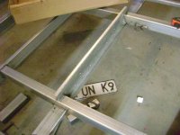
Now I am going to construct this trailer exactly opposite to how I normally construct them. I am going to construct the frame first ,then install the diamond plate later.

Normally I spot weld the floor together first, then stitch weld the cross members to the floor.
After that the main rails are welded to the floor cross-member assembly, this guarantees the frame is perfectly square to the floor [provided the floor pieces are guillotined correctly]
I normally never need to diagonally adjust the frame because it always fits perfectly.

see photos of how I used to do it.
 

Attachments

  • DSC04200.JPG
    DSC04200.JPG
    142.3 KB · Views: 334
  • DSC04209.JPG
    DSC04209.JPG
    140.8 KB · Views: 328
Last edited:
OP
K

kerrynzl

Well-known member
Joined
Nov 8, 2013
Messages
5,054
Location
Tauranga, New Zealand
So I made a simple Jig from scraps to substitute for the floor to help get the frame square to the floor and get the shape correct.
Please note the floor will sit 25mm lower than the frame inside the outer perimeter ,so this is necessary for fitment.
 

Attachments

  • DSC04353.JPG
    DSC04353.JPG
    131.8 KB · Views: 231
OP
K

kerrynzl

Well-known member
Joined
Nov 8, 2013
Messages
5,054
Location
Tauranga, New Zealand
I made these simple spacer/braces to clamp the main frame rails.

This keeps the frame rails parallel and also square [ vertical ] .

The main frame will be 100 x 50 x 3mm wall [ 4 x 2 x 1/8"] which is plenty strong enough.
 

Attachments

  • 1.JPG
    1.JPG
    138.7 KB · Views: 123
OP
K

kerrynzl

Well-known member
Joined
Nov 8, 2013
Messages
5,054
Location
Tauranga, New Zealand
I got all the steel cut and pre-drilled. My drill press has been modified with a cross-slide table so I can bolt 2 vices to it [1 vice is used to clamp a “stopper” to speed up the process]

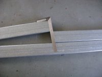
To cut the angle for the dovetail which has a 100mm drop [4”] , I cut the dovetail 1m long and square.
Then this piece was place on top of the main frame rail and I used a square to mark the angle.

Normally I cut the frame square and the dovetail on an angle, but this time it was opposite because there will be a cross-member on the dovetail side of this join [ to get better cross-member spacing]
A cross-member is not needed at this point because a correctly folded piece of diamond plate is strong enough without it. With this trailer there will be slide out “Ramp Drawers” that need to be attached to this cross-member
 

Attachments

  • 1...JPG
    1...JPG
    142.7 KB · Views: 168
  • 1..JPG
    1..JPG
    141.2 KB · Views: 181
  • 2.JPG
    2.JPG
    136.7 KB · Views: 184
  • 2..JPG
    2..JPG
    143.9 KB · Views: 195
OP
K

kerrynzl

Well-known member
Joined
Nov 8, 2013
Messages
5,054
Location
Tauranga, New Zealand
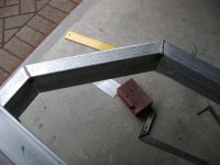
Next stage is to weld up the main frame rails on the inside only [because there is a cross-member that covers this weld] The other 3 welds are done when everything else as tack welded together.
To weld theses rails, I grind a V then the weld is ground level afterwards.

The main rails are clamped on top of the steel used for the tongue to get it all straight.
Once it was welded , it was flipped over then the opposite side gets the same treatment.

They were clamped together to get the angles as a matched pair

Both left and right rails are shown side by side.
 

Attachments

  • 6.JPG
    6.JPG
    141.2 KB · Views: 127
  • 5.JPG
    5.JPG
    140.6 KB · Views: 134
  • 4.JPG
    4.JPG
    133.9 KB · Views: 141
  • 3.JPG
    3.JPG
    139.8 KB · Views: 152
  • 3..JPG
    3..JPG
    139 KB · Views: 155
OP
K

kerrynzl

Well-known member
Joined
Nov 8, 2013
Messages
5,054
Location
Tauranga, New Zealand
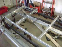
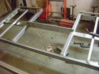
Now it is time to start piecing it all together.

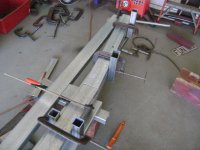
I used 4 blocks of wood and laid across them some steel [I later used this steel for the tongue], then shimmed up the corners to get both pieces level.
Then the main frame rails were clamped to these pieces using the spacer/braces [from post # 4]

The frame rails are 100 x 50 and the cross-members are 75 x 50 spaced evenly at 400mm centres for 1200 wide sheets of diamond plate.
The cross-members will be flush with the underside to give the deck a 25 mm recess on the top [ less the thickness of the deck ]

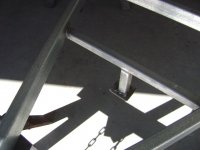
The 3rd cross-member in front of the dovetail [above the rear axle] is drilled to run wires inside for the electric brakes.
I threaded some curtain wire inside before it is welded in [ the curtain wire is used to draw the wire through when finished ]

2 pieces of steel are clamped lengthways to get the front piece of the outer frame level. Then the corner pieces were tacked in place.
I used the jig from posting #3 for trial fitment , a slight massaging of 1 corner piece was required then it was all tacked together
 

Attachments

  • 8.JPG
    8.JPG
    144.2 KB · Views: 158
  • 7.JPG
    7.JPG
    141.5 KB · Views: 157
  • 6.JPG
    6.JPG
    143.1 KB · Views: 160
  • 4.JPG
    4.JPG
    145 KB · Views: 176
  • 3.JPG
    3.JPG
    143.1 KB · Views: 175
  • 2.JPG
    2.JPG
    139.1 KB · Views: 149
  • 1.JPG
    1.JPG
    137 KB · Views: 155

toofart

Well-known member
Joined
Sep 27, 2013
Messages
280
Location
Qc
Good to see you posting up a build :)

Now I am going to construct this trailer exactly opposite to how I normally construct them. I am going to construct the frame first ,then install the diamond plate later.

If your technique works well for you, why are you changing for this build?
 
OP
K

kerrynzl

Well-known member
Joined
Nov 8, 2013
Messages
5,054
Location
Tauranga, New Zealand
Good to see you posting up a build :)


If your technique works well for you, why are you changing for this build?

I'm going to glue the diamond plate in after the frame is built.
The last time I got a trailer "hot dip galv'd" they destroyed it with heat warpage.

This way I can built the frame from Duragal and install the deck afterwards

This trailer is a 1 off experiment.[that I am building for a client]
 
Last edited:
OP
K

kerrynzl

Well-known member
Joined
Nov 8, 2013
Messages
5,054
Location
Tauranga, New Zealand
The rear dovetail is getting finished here.
I got a piece of 3mm [1/8”] folded in a pressbrake for the license plate bracket. The wiring needs to run across the front this section and the plate bolts on behind .
It is pre-drilled for the license plate and the lights.

The Ramp drawers can be made for diamond plate ramps up to 540mm width .
If you look closely at the 75mm x 25mm [3”x 1”]cross-members in the ramp drawers there is some curtain wire inside them, so that the wiring can cross over from 1 taillight to the other and also pick up the license plate lights

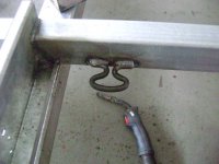
While the trailer is upside down 2 lasing loops [tie-downs] are welded underneath inside the split dovetail. These loops are a marine item, they’re great for shackles and ratchet tie downs but also a rope with loops can loop over them [ no moving parts to fail ]
 

Attachments

  • 3..JPG
    3..JPG
    121.1 KB · Views: 132
  • 3...JPG
    3...JPG
    123 KB · Views: 141
  • 2....JPG
    2....JPG
    109.5 KB · Views: 131
  • 1.JPG
    1.JPG
    107.4 KB · Views: 110
  • 2..JPG
    2..JPG
    109.1 KB · Views: 109
  • 2...JPG
    2...JPG
    115.9 KB · Views: 116
OP
K

kerrynzl

Well-known member
Joined
Nov 8, 2013
Messages
5,054
Location
Tauranga, New Zealand
How much weight do you think this trailer will be able to haul?


“Able to Haul” and “Legal to Haul” are different.

I will rate the trailer to 2500 kg GVW [5500 lbs] , by keeping it under this weight limit has advantages meeting our legal requirements.

So if I can get close to target weight it should be able to haul a 4000-4100 lb payload when towed behind a Jap pickup.

Vehicle trailers are easy, because the 4 x footprints are out by the frame rails [ that's why we can build open centre trailers]
And if the trailer is designed to be balanced correctly these footprints are within 1m of the end suspension load points of the trailer.
Add to that, a correctly designed fender back will contribute a lot to the beaming strength of the trailer [near the centre where the load forces are greatest ]

I’ve built a similar trailer for a friend who has a “different interpretation” of our towing laws.
He regularly tows heavy weights around. He once showed me a photo and a weighbridge docket with 6900 kgs all up weight [ 15200 lbs ]
So engineering wise , they are plenty strong enough
 

koditten

Well-known member
Joined
Apr 10, 2008
Messages
5,528
Location
Midland, Michigan
So if I can get close to target weight it should be able to haul a 4000-4100 lb payload when towed behind a Jap pickup.

Just curious here. Is that last phrase common vernacular in your part of the globe? Around here, some thin skinned people might take offense.

And...about time you did a build:)

I'm in.

KO
 
OP
K

kerrynzl

Well-known member
Joined
Nov 8, 2013
Messages
5,054
Location
Tauranga, New Zealand
Just curious here. Is that last phrase common vernacular in your part of the globe? Around here, some thin skinned people might take offense.

And...about time you did a build:)

I'm in.

KO

Haha!

About time you chimed in Kirk!

The correct phrase is "Jap Ute" ,we don't use the term "pickup" downunder
The beloved UTE is an abbreviation of "Coupe Utility" but that term was only used in the 1940's as a product launch

90% plus tow vehicles in NZ [and Aus ] are Hilux's, Navara's, L200's, and Courier/Rangers [ plus a few SUV's like Landcruisers and Patrols ]
And the beloved Falcon and Holden Ute

Any modern USA pickup needs to be converted to RHD for our roads [this adds $12k + to the price]
 

Thumper68

Well-known member
Joined
May 16, 2013
Messages
5,134
Location
Duluth MN
My cousin and her husband live in NZ he's a native and she's a transplant, he so much wants me to take apart and ship him a complete mid '70's GMC pick-up like my K20.

He liked that fact that I can with a trailer load up all my tools and equipment and the supplies for a 24x24 garage in one load, the summer he was here working with me we did seven or eight of them.

He has two hilux's now and hates them.

I love the direction your trailer is taking, looks like a lot of thought and skill went into the design
 
OP
K

kerrynzl

Well-known member
Joined
Nov 8, 2013
Messages
5,054
Location
Tauranga, New Zealand
He liked that fact that I can with a trailer load up all my tools and equipment and the supplies for a 24x24 garage in one load, the summer he was here working with me we did seven or eight of them.

He has two hilux's now and hates them.

I love the direction your trailer is taking, looks like a lot of thought and skill went into the design

That is the very reason I like smaller trailers, the supplies from a 24x24 garage don't get loaded and unloaded by themselves :D
Spending most of my life around racing has taught me this, we need to leave **** at home and learn to enjoy the sport.

My skills are mediocre, the most difficult part is the "thought". I always believe quality is an Attitude [ it really takes no more effort to do things properly ]
 

Thumper68

Well-known member
Joined
May 16, 2013
Messages
5,134
Location
Duluth MN
That is the very reason I like smaller trailers, the supplies from a 24x24 garage don't get loaded and unloaded by themselves :D
Spending most of my life around racing has taught me this, we need to leave **** at home and learn to enjoy the sport.

My skills are mediocre, the most difficult part is the "thought". I always believe quality is an Attitude [ it really takes no more effort to do things properly ]

:lol: I wasn't talking about all stuff from in a garage I was talking about everything needed to build one.

It's kind of nice when building out in the sticks and you can bring everything in one load. Of course back then I had a 20k rated goose neck, that was built in my driveway.
 
OP
K

kerrynzl

Well-known member
Joined
Nov 8, 2013
Messages
5,054
Location
Tauranga, New Zealand
:lol: I wasn't talking about all stuff from in a garage I was talking about everything needed to build one.
.

I've probably been exposed to too much Avgas, to spot that!

But in my defence , I've seen some builders that could build a complete garage from the materials carried in the back of a Ute.[ before our present building codes came into force :D ]
 
OP
K

kerrynzl

Well-known member
Joined
Nov 8, 2013
Messages
5,054
Location
Tauranga, New Zealand
Now is time for the tedious part.

I needed to attach around the inside edge of the frame rails something to support the sides of the deck.

I cut sections of 30mm x 3mm Angle then glued them to the the sides and welded a few spots to hold them in place until the glue sets.
These pieces of angle need to be at the same level on the top side as the cross-members.

I clamped pieces of steel along the cross-members to get them all level.

It would have been easier to simply attach the deck directly on top of the rails, but this was done purely for cosmetic reasons [“**** factor” is the Kiwi term]

While the trailer is still upside down I welded the support rails at the rear for the pull out ramps.
 

Attachments

  • 5.JPG
    5.JPG
    122.8 KB · Views: 89
  • 4.JPG
    4.JPG
    127.6 KB · Views: 90
  • 3.JPG
    3.JPG
    142.4 KB · Views: 89
  • 2.JPG
    2.JPG
    141.4 KB · Views: 87
  • 1.JPG
    1.JPG
    143.3 KB · Views: 96
To avoid these ads, REGISTER NOW!
OP
K

kerrynzl

Well-known member
Joined
Nov 8, 2013
Messages
5,054
Location
Tauranga, New Zealand
Here is the Tongue [called the Drawbar in NZ] getting mocked up.
Note the string line used to centreline everything, this is vital if you want the trailer to handle nicely.

I use a bit of math [actually an online calculator] to figure out the pie cuts.
I posted how to do this on toofart’s thread http://www.garagejournal.com/forum/showthread.php?t=265528 [free plug here for you mate!]

This trailer is also going to be a tilt trailer, so I deliberately make the cutback style tongue 5mm each side narrower than the frame. [1/4”]
This actually looks good when the trailer is upright, but terrible from the underside.

I do this to give the tilt tongue clearance behind the fenders, and it stops dirt / water stains running from the frame to the tongue.
I calculate the pie cuts so the rear is 12mm [overall] wider , this is to allow for shrinkage when the cuts are welded.
If a mistake is made here, the tongue can simply be shortened under the coupler to correct the angle for the cut back sides [so far my calculations have been pretty good ]

Once this is done, the suspension is mocked up. The end hangers are important as they dictate the wheelbase.
I clamp a bar across the springs to get them perpendicular. I’ve come across springs before with the eyes rolled incorrectly so this allows for that [ the springs are also marked for their particular position ]
 

Attachments

  • 7.JPG
    7.JPG
    136.2 KB · Views: 138
  • 6.JPG
    6.JPG
    127 KB · Views: 131
  • 5.JPG
    5.JPG
    121.5 KB · Views: 131
  • 4.JPG
    4.JPG
    142.7 KB · Views: 132
  • 3.JPG
    3.JPG
    142.4 KB · Views: 157
  • 2.JPG
    2.JPG
    141 KB · Views: 141
  • 1.JPG
    1.JPG
    142.6 KB · Views: 156
OP
K

kerrynzl

Well-known member
Joined
Nov 8, 2013
Messages
5,054
Location
Tauranga, New Zealand
I forgot to photograph the pivots for the tongue being built ,so I’ve taken some photos afterwards to give you all the general idea.

It was surprisingly simple.

I found a bracket used for rollers on a boat trailer the fitted neatly over the outside of the existing spring hanger.
It had the same bolt hole and the same width, so I can use the same “lock tab” with a slightly longer bolt.
When I mocked up the suspension , I bolted this in and welded it horizontally to the rear of the tongue.
[best of all, it was cheap and off the shelf]
 

Attachments

  • 9.JPG
    9.JPG
    137.3 KB · Views: 117
  • 8.JPG
    8.JPG
    139 KB · Views: 105

toofart

Well-known member
Joined
Sep 27, 2013
Messages
280
Location
Qc
Nice work! So far it's looking very North American, so your #6 requirement is met.

I like the usage of a string to center up the hitch with the trailer. I used a long piece of tube, but I think your usage of the string is more accurate as the tube can have a crown to it.

Thanks for the plug :beer:
 

William Payne

Well-known member
Joined
Mar 15, 2010
Messages
8,090
Location
Wanganui, New Zealand
I’ve built a similar trailer for a friend who has a “different interpretation” of our towing laws.
He regularly tows heavy weights around. He once showed me a photo and a weighbridge docket with 6900 kgs all up weight [ 15200 lbs ]
So engineering wise , they are plenty strong enough

You wouldn't happen to be able to share his name would you. I know someone who matches that discription.
 
OP
K

kerrynzl

Well-known member
Joined
Nov 8, 2013
Messages
5,054
Location
Tauranga, New Zealand
You wouldn't happen to be able to share his name would you. I know someone who matches that discription.

All I will say is "Glenn"
Here is a photo showing a 4ton payload on one of these trailers. He had to cut the frame rail on the truck .[total weight here is over 10,000lbs]

I have a few more photos but they all show the plate numbers of his vehicle [I won't identify him on a public forum ]
 

Attachments

  • 1..JPG
    1..JPG
    146.3 KB · Views: 297
Last edited:
OP
K

kerrynzl

Well-known member
Joined
Nov 8, 2013
Messages
5,054
Location
Tauranga, New Zealand
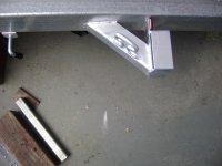
I made a few components up. The pieces of square tube and the plates [with holes] make up taillight brackets. The 2 triangle pieces pictured are latch receivers for the tilt when using spring bolts

The trailer buyer contacted me an wanted a few changes made [ which might affect the target weight ]
He wanted to opt for wooden ramps, because they are a cheap replaceable component that gets a lot of abuse.

I needed to modify the ramp drawers for a narrower 12 x 2 wooden ramp. It is also designed so when the ramp is fully extended it can be shifted sideways [for narrow track widths ]

Once these modifications were completed, and the latch receivers were welded in place the trailer frame is then flipped over so I can weld the topside.
The trailer frame is quite lightweight at this stage, me and my neighbour simply lifted it up by hand and flipped it over.

Shown is a photo of the latch receivers welded in place.
Now that the trailer frame is upright, I use a straightedge across the rear to weld the taillight brackets on [ they need to look level when following from behind]

The trailer buyer also wanted a cross-member added to the tongue for a detachable electric boat winch. He also wanted to upgrade from fibreglass fenders to steel teardrop fenders.
I have a plug for making fibreglass teardrop fenders with the backs already as part of them [they are very lightweight]

Why am I playing around with fibreglass? It is a filthy habit I picked up from owning Corvettes

Well I guess I’ll have to glue up some steel fenders.
 

Attachments

  • 7.JPG
    7.JPG
    140.7 KB · Views: 87
  • 6.JPG
    6.JPG
    142.4 KB · Views: 80
  • 5.JPG
    5.JPG
    143.3 KB · Views: 89
  • 4.JPG
    4.JPG
    143.5 KB · Views: 83
  • 3.JPG
    3.JPG
    145.5 KB · Views: 89
  • 2.JPG
    2.JPG
    110.8 KB · Views: 94
  • 1.JPG
    1.JPG
    135.9 KB · Views: 83
OP
K

kerrynzl

Well-known member
Joined
Nov 8, 2013
Messages
5,054
Location
Tauranga, New Zealand
Here's a couple of photos of the tongue with the welding all finished
[ showing the cross-member for the detachable winch ]
 

Attachments

  • 8.JPG
    8.JPG
    139.6 KB · Views: 110
  • 9.JPG
    9.JPG
    141.4 KB · Views: 101
OP
K

kerrynzl

Well-known member
Joined
Nov 8, 2013
Messages
5,054
Location
Tauranga, New Zealand
Now the fun part.......Installing the diamond plate deck.

The Diamond plate is 5mm thickness Aluminium.
After pricing Hot Dip Galvanizing of Steel [ or Lucky Dip Galvanising ] Aluminium was a more attractive alternative.

One very important thing to consider when using Aluminium. Steel and Aluminium are not very good “Bed Partners” , they should never touch each other or there will be corrosion.

The Deck was Guillotined 1.5mm [1/16”] smaller around the whole outside then dropped in for trial fitment.
A couple of adjustments were made with a “flap disc” on a grinder where the corner welds were. But overall it was a good fit.

I went around the whole trailer and dabbed pieces of 2 sided tape at approx 300mm [12”] intervals. The purpose of the tape is to provide clearance between the Frame and the Aluminium.
Then I started from the front and worked my way towards the rear pouring on the glue.

I masked along the edges of the Aluminium where the joins are . Any excess glue that squeezed out was wiped flat with my finger and the tape was peeled off.

In a job like this, you cannot have enough clamps , I used a few pieces of steel and some clamps to lightly clamp the joins to keep them at the same level .
The fold in the dovetail required the most time. I was very careful not to over tighten the clamps.

All up this particular job took 3 hours.
The most difficult part was ,having to walk away from it [ and keeping my fingers off it, while it cures ]
 

Attachments

  • 7.JPG
    7.JPG
    140.8 KB · Views: 133
  • 6.JPG
    6.JPG
    139.4 KB · Views: 169
  • 5.jpg
    5.jpg
    27.3 KB · Views: 141
  • 4.JPG
    4.JPG
    143.4 KB · Views: 142
  • 3.JPG
    3.JPG
    142.6 KB · Views: 139
  • 2.JPG
    2.JPG
    141.2 KB · Views: 142
  • 1.JPG
    1.JPG
    142.5 KB · Views: 142
OP
K

kerrynzl

Well-known member
Joined
Nov 8, 2013
Messages
5,054
Location
Tauranga, New Zealand
What is the glue you use?

I use a Bostik product called “Simson ISR 70-03”

To give you an idea of it’s tension strength , I got small 2 pieces of 2”x 2” steel tube and masked off 1 square inch then glued them together.
After a week of curing , I passed a chain through one of the pieces and hung a 44 lb [20 kg] barbell plate off it.
It could have easily held more ,but i only had one barbell plate.

I decided to do another test to see if it would hold on a painted surface.
So I glued together 2 pieces of offcut steel that have been powder coated.
Again after a week of curing , I put one piece in my vice and used a pry bar to separate them.

If you look closely at the photo, the glue literally pulled the powder coating off the steel

So I can safely say “It sticks like **** too a blanket” [the correct Kiwi term]


To put it into perspective, there is 2150in² of surface that is glued on this trailer [ each cross-member is 152in² ] so if we multiply that by the known 44 lbs
There is enough glue to support 94600 lbs under tension
 

Attachments

  • 1.JPG
    1.JPG
    144.4 KB · Views: 110
Last edited:

Thumper68

Well-known member
Joined
May 16, 2013
Messages
5,134
Location
Duluth MN
I'm very impressed so far, am I seeing this right and it's a single axel?

I'm working up plans for a twin axel low deck 5x8 dump with removable sides, right now it's more of a excersize to figure out cost/materials it might get built someday.

Gluing a AL deck to the steel frame would be a great option for me.
 
OP
K

kerrynzl

Well-known member
Joined
Nov 8, 2013
Messages
5,054
Location
Tauranga, New Zealand
I'm very impressed so far, am I seeing this right and it's a single axel?

I'm working up plans for a twin axel low deck 5x8 dump with removable sides, right now it's more of a excersize to figure out cost/materials it might get built someday.

Gluing a AL deck to the steel frame would be a great option for me.

It is tandem [ look at post #29 ,the 4th & 6th photo ]
I don't waste my time with single axle trailers because it brings all the cheapskates out of nowhere. They expect them for 1/2 price.

The cost of some heavy load rated tyres for a single can be more than the cost of an idler axle and springs

A dump trailer with removable sides [L & R] or Ends [Fr & Rr] ?

Removable sides has no advantage unless you raise the deck to clear the top of the wheels [ platform trailer ]

In NZ we always have removable [or drop down] front and rear tailgates
 

toofart

Well-known member
Joined
Sep 27, 2013
Messages
280
Location
Qc
Does the sealant provide sufficient separation between steel an AL to prevent corrosion?
 
OP
K

kerrynzl

Well-known member
Joined
Nov 8, 2013
Messages
5,054
Location
Tauranga, New Zealand
Does the sealant provide sufficient separation between steel an AL to prevent corrosion?

Thanks for those specs [ I'll glue my race car together now I know this :D ]

The separation only needs to be tiny, but 1mm [40 thou] is the target amount
to allow some flexibility.

I used 2 sided tape [double backed tape] to create some separation.
A coachbuilder told me that trick.

I've seen matchsticks used, and also pieces of plastic cord from a line trimmer.

The interesting thing about using glue is IF the deck flexes from too much weight, it will spring back to shape.
Whereas if it was welded ,the deck will crease over the frame underneath.
 
OP
K

kerrynzl

Well-known member
Joined
Nov 8, 2013
Messages
5,054
Location
Tauranga, New Zealand
After the glue has set for 24 hours the deck can be walked/jumped on.
Because the deck has 1.5mm [1/16”] clearance around the outside it needs to be sealed. [ the gap looks terrible ]

So the deck was masked 2mm from the edge, and the frame was also masked about the same distance.
I had to be patient and get the masking straight.

I needed to push the masking tape really hard into the tread patterns on the edge of the deck.
Then I ran a bead of glue around the edge of the trailer [ it makes a good sealer and is paintable too ]

Then I dipped my finger into some “wax and grease remover” and ran my finger around the edge.
Wax and grease remover is the best solvent for removing this glue if you get it on something.

I leave the glue for about 2-3 minutes then pull the tape off [don’t let the glue set or it goes rubbery ]

When I was finished with this, I banged some plastic cap onto the ends of the frame rails. [ These were left open to thread the wiring inside the frame rails ]
 

Attachments

  • 7.JPG
    7.JPG
    141.2 KB · Views: 145
  • 6.JPG
    6.JPG
    146 KB · Views: 122
  • 5.JPG
    5.JPG
    142.4 KB · Views: 109
  • 4.JPG
    4.JPG
    143.9 KB · Views: 107
  • 3.JPG
    3.JPG
    140.4 KB · Views: 109
  • 2.JPG
    2.JPG
    141.3 KB · Views: 134
  • 1.JPG
    1.JPG
    141.2 KB · Views: 113

SLYDIT

Well-known member
Joined
Mar 28, 2014
Messages
195
Looks great. might see it being towed down cameron road!
cheers. Glenn. ( no not that one)
 
OP
K

kerrynzl

Well-known member
Joined
Nov 8, 2013
Messages
5,054
Location
Tauranga, New Zealand
While the glue was curing on the deck, I prepared some steel fenders by gluing the steel fender backs into the fenders.

I get the fenders rolled into a slightly tighter radius to suit the wheelbase of the suspension kits available in NZ.
So afterwards I have to trim off the bottom edges and radius the corners so the fenders don’t look like vintage motorcycle fenders.

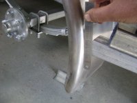
The fenders are mocked up using clecos, so I can fabricate some “nerf bars” because the buyer also wanted these added.
Setting up the fenders requires a straight edge along the top, plus the backs needed to be vertical.
I also set the top of the fenders at a height of 8” above the deck so car doors can open above them.

After I have fabricated the nerf bars, the fenders will be removed and painted separately [ this I hadn’t planned on, I was hoping to pre-finish the fenders in Gel-coat ]
 

Attachments

  • 7.JPG
    7.JPG
    137 KB · Views: 94
  • 6.JPG
    6.JPG
    143.5 KB · Views: 93
  • 5.JPG
    5.JPG
    141.6 KB · Views: 121
  • 4.JPG
    4.JPG
    142 KB · Views: 111
  • 3.JPG
    3.JPG
    145.4 KB · Views: 98
  • 2.JPG
    2.JPG
    142.8 KB · Views: 103
  • 1.JPG
    1.JPG
    142.1 KB · Views: 101
OP
K

kerrynzl

Well-known member
Joined
Nov 8, 2013
Messages
5,054
Location
Tauranga, New Zealand
The nerf bars need to be trial fitted to each fender in place.

I measure a suitable length and width and mark these measurements onto a builders square.
Then I clamp a piece of Angle to the square and scribe the cuts [ this method is simple and doesn’t require any math ] One must be inverted to be the opposite side.
These pieces are then clamped to the trailer using a straight edge across the top to keep them level. Then I use a ruler to scribe the angle [curvature] of the fender.

Once these are cut the nerf bar can slid closer to the fender for a snug fit.
I also drill a hole in the side brackets for a rivet to the fender ,hidden under the angle

The whole nerf bar assembly is clamped and cleco’d into place and spot welded [I also spray a coat of anti-splatter on the fender]
The fender is then removed and the nerf bar is fully welded.

Once the welds have cooled I reassemble the fenders with cleco’s ,then mark and drill the fenders for clearance lights [a legal requirement in NZ]

Then the fenders are removed for painting. Three cheers for cleco’s for all the times I had to fit and remove the fenders.
 

Attachments

  • 6.JPG
    6.JPG
    142.8 KB · Views: 76
  • 5.JPG
    5.JPG
    144.3 KB · Views: 75
  • 4.JPG
    4.JPG
    143.4 KB · Views: 70
  • 3.JPG
    3.JPG
    143.5 KB · Views: 70
  • 2.JPG
    2.JPG
    140.8 KB · Views: 68
  • 1.JPG
    1.JPG
    136.3 KB · Views: 69
  • 7.JPG
    7.JPG
    141.4 KB · Views: 83
To avoid these ads, REGISTER NOW!
Top Bottom