To avoid these ads, REGISTER NOW!

BIG Trencher vs Cat 308 for digging through "forested" area

To avoid these ads, REGISTER NOW!

theoldwizard1

Well-known member
Joined
Feb 22, 2011
Messages
43,233
Location
SE MI
Next year i'm planning a dam to build a big "water battery" which will store ~30 days power :)

Now that is a project I would like to follow with lots of pictures !

I would also like to see your turbine/generator and battery/charger/inverter setup !
 
OP
E

Ebenbayer

Member
Joined
Dec 18, 2014
Messages
13
Location
Upstate NY
you got it OldWizard-- small amounts of continuous power compounding over time-- far out performs our much larger solar array (which "Peaks" at 3,000 watts at noon, but seems to be a pretty poor performer at 3 am )

Here are a few shots of the generator its self:

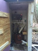
*Looking at the 4'x4' insulted building (needs to get leveled and moved another 30 ft down the hill.

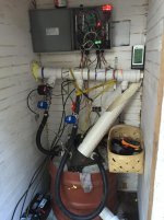
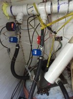
*Looking into the building; manifold of PVC; 3x 3/4" 12 V DC electrically actuated ball valves.

*Pressure gauge showing current pressure

*Temp gauge showing current water temp (very important!!!)

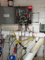
*there is a micro controller in the center that communicates with a local cell tower. Essentially I can "text" this unit and say things like "valve 1 on" and it will turn on, etc. Saves me a half mile hike when I need to change out-put based on demand or stream flow.

Its a bit messier then i would like but always a balance of doing the job right and getting the unit operational :)
+ leaves options for future projects!!

Water temp was 35 Degrees today w/ air temp at 17 F. tomorrow will measure incoming water temp and determine loss over length of pipe. May need to still shut down this winter if things get much closer to the magic 32 F!
 

Attachments

  • Gen Distance.jpg
    Gen Distance.jpg
    152.3 KB · Views: 24
  • Gen House1.jpg
    Gen House1.jpg
    150.2 KB · Views: 26
  • geninterior.jpg
    geninterior.jpg
    140.9 KB · Views: 27
  • geninterior2.jpg
    geninterior2.jpg
    139.7 KB · Views: 29
  • Valve Close up.jpg
    Valve Close up.jpg
    140.6 KB · Views: 28
  • Water Temp.jpg
    Water Temp.jpg
    143.2 KB · Views: 26

theoldwizard1

Well-known member
Joined
Feb 22, 2011
Messages
43,233
Location
SE MI
you got it OldWizard-- small amounts of continuous power compounding over time-- far out performs our much larger solar array (which "Peaks" at 3,000 watts at noon, but seems to be a pretty poor performer at 3 am )

Here are a few shots of the generator its self:

*Looking at the 4'x4' insulted building (needs to get leveled and moved another 30 ft down the hill.

*Looking into the building; manifold of PVC; 3x 3/4" 12 V DC electrically actuated ball valves.

*Pressure gauge showing current pressure

*Temp gauge showing current water temp (very important!!!)
I would think this would not be too much of an issue with constant flow. How many GPM ?

*there is a micro controller in the center that communicates with a local cell tower. Essentially I can "text" this unit and say things like "valve 1 on" and it will turn on, etc. Saves me a half mile hike when I need to change out-put based on demand or stream flow.
Very cool !

Is that your "battery bank" ?

1/2 mile is a lot of wire but I assume it is high voltage AC, correct ?
 
To avoid these ads, REGISTER NOW!
OP
E

Ebenbayer

Member
Joined
Dec 18, 2014
Messages
13
Location
Upstate NY
I have an 48 V fork truck battery bank that I got out of a scrap unit. I've worked it back into good condition, but basically idea is to use the hydro for most of what a "battery" would do off grid.

I ran 2500 ft of 6 gauge three strand direct burial AL. Its currently running @ 120 V DC (w/ two wires tied together on - side). The hydro produces "wild" three phase AC which is rectified at site. I could send the wild three phase up the hill and rectify right before the charge controller. I don't think this buys me anything, though. Charge controller at charging shed takes sets the power point (105 VDC, 15 VDC is lost to resistance up the hill) and then charges the battery bank.

A 3.6KW inverter feeds everything else.

This is version 6 or 7 and is starting to work pretty well. (Version 1.0 was 12 V, very basic short hydro, and a car style square wave inverter).

I have water resource (at least this time of year) to make double power (1.2 KW) at the generator head. But to need to increase pipe diameter and run a second wire to overcome various efficiency losses (head loss, resistive loss). so may or or may not happen :) (The 4" PVC mainline I buried can carry way more water, only 1% power lost due to flow loss in that section!)

I'm flowing ~ 40 GPM right now; I also thought it wouldn't freeze,but last winter when it dropped beneath 0 F something froze... and then it backed up and everything froze splitting 800' ft of 3" PVC pipe (!!! ).

I have 1/3 of the line buried now ( w/ 1" insulation on top of line). the other 1/3" is 2" pipe so the water is moving faster, and its fingers crossed for the last 400' ft of pipe :)
 

theoldwizard1

Well-known member
Joined
Feb 22, 2011
Messages
43,233
Location
SE MI
I ran 2500 ft of 6 gauge three strand direct burial AL.
$$$$ :shocking:

Its currently running @ 120 V DC (w/ two wires tied together on - side). The hydro produces "wild" three phase AC which is rectified at site. I could send the wild three phase up the hill and rectify right before the charge controller. I don't think this buys me anything, though. Charge controller at charging shed takes sets the power point (105 VDC, 15 VDC is lost to resistance up the hill) and then charges the battery bank.
I'm not EE, but wouldn't there be less loss with AC over long distances and rectifying it "up the hill" ? (This was the big argument between Edison and Tesla.)

A 3.6KW inverter feeds everything else.

This is version 6 or 7 and is starting to work pretty well. (Version 1.0 was 12 V, very basic short hydro, and a car style square wave inverter).
What brand and model of turbine, generator and inverter are you running ?

I'm flowing ~ 40 GPM right now; I also thought it wouldn't freeze,but last winter when it dropped beneath 0 F something froze... and then it backed up and everything froze splitting 800' ft of 3" PVC pipe (!!! ).

I have 1/3 of the line buried now ( w/ 1" insulation on top of line). the other 1/3" is 2" pipe so the water is moving faster, and its fingers crossed for the last 400' ft of pipe :)

Ouch, on the split pipe ! :( Plans to go 4" all the way ?

What your total head ? Any issues with discharge ?
 
Last edited:

theoldwizard1

Well-known member
Joined
Feb 22, 2011
Messages
43,233
Location
SE MI
I am not an expert or even a beginner.

I thought originally AC and DC power was distributed in the US. AC won because there was less power loss than DC.
TRUE !

Edison wanted DC, but it would require power station every 1-5 (?) miles.

There are a few special cases where high power DC is a better fit.
 
To avoid these ads, REGISTER NOW!
Top Bottom