freshintulsa
Active member
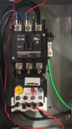
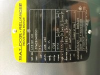
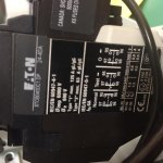
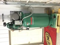
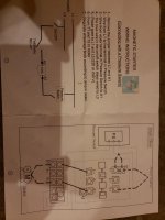
Hello all. I recently got my new compressor and am a little confused on hooking up my input power. This is 230volts SINGLE phase. My confusion is in the contactor/starter. It has 3 legs and I thought at first that they sent me the wrong one. I looked it up and it is good for single and 3 phase. It is an Eaton C25DNF340 contactor.
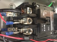
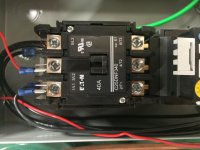
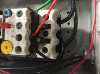
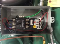
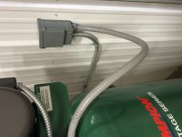
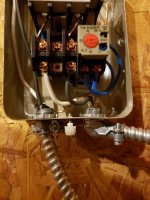
The two hot legs from the motor are coming into the bottom of the contactor/starter assembly. They are in the T1 and T3 terminals. Pictures to follow at the end.
The T2 terminal jumps up to the L3 terminal. I believe my two hot legs should tie into the L1 and L2 terminals and obviously my ground will go to the grounding lug in the box.
I'm no electrical expert, but have wired up my share of machines in the past, but I just thought I would ask the collective group here, who many of are geniuses!
Also, I was going to use an inline disconnect to turn off power to the compressor, but a buddy of mine at work said he used a simple switch that he wired in his box on the compressor. Has anyone done this? Any suggestions on a switch to use that can handle 60 amps?
Thanks again!
Doug