To avoid these ads, REGISTER NOW!

Looking for some advice on how to layout a custom accessory bracket

superskaterxes

Well-known member
Joined
Jul 31, 2013
Messages
418
Location
Maryland
Hey guys,

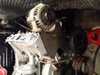
so i am starting on my first LS engine build and i have lots of previous fabrication experience for making custom parts but i am just starting out on a project where i need to relocate some of my accessories using a custom bracket. Lots of companies make different accessory relocation kits but they tend to be expensive and i havent found one that fits exactly what i want to do.

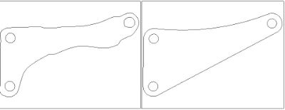
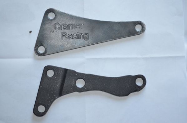
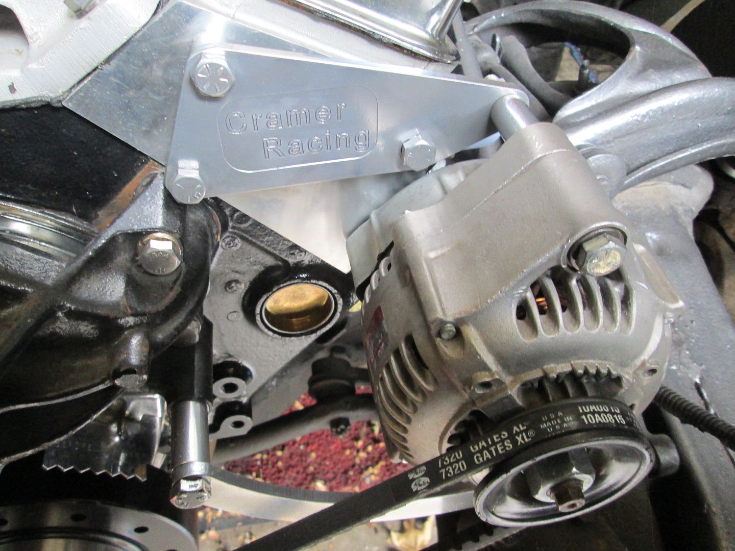
Here is an example of one for those of you who dont know:

drives+high+ps+1.jpg


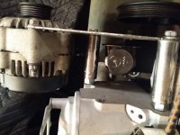
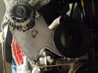
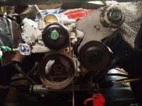
anyway what i am not sure about is figuring out how to locate the bolt pattern/spacing of the block/head so i can at-least get something bolted to the engine.

Are there any tricks to doing this? I figured i could measure from a central point or even trace the bolt pattern onto a piece of paper using the side of a pencil (think kids fossil rubbing/tracing at the zoo) but i was looking for some suggestion from some more experienced members.
 
To avoid these ads, REGISTER NOW!

jimgood

Well-known member
Joined
Aug 4, 2014
Messages
2,394
Location
Marshall, VA
I've never done it before but I don't think paper tracing will work because you have mounting holes in different planes.

I'd probably make a template by using small pieces of 1" flat bar. I'd start with the holes that are in the same plane by measuring the distance between the two and drilling holes in a piece of flat bar at that distance. Find or make spacers for the top bar to move it out so it's on the same plane as the bottom two holes. Bolt the top on with the spacers under it. Bolt the bottom bar on. The cut two pieces of bar to join them and tack weld it. There's your template. See my crude modifications to your pic.

Again, I've never done it so there's probably an easier way. If you're lucky, it will be reversible for the other side.
 

Attachments

  • template.jpg
    template.jpg
    96.7 KB · Views: 46

rockwithjason

Well-known member
Joined
Jan 8, 2006
Messages
2,633
Location
Las Vegas
use some cardboard cut roughly to the shape you have in mind then trim and fit about a billion times until you have it. you can use transfer punches to mark the holes or some short sections of all thread in the holes and punch thru
 
OP
S

superskaterxes

Well-known member
Joined
Jul 31, 2013
Messages
418
Location
Maryland
I've never done it before but I don't think paper tracing will work because you have mounting holes in different planes.

I'd probably make a template by using small pieces of 1" flat bar. I'd start with the holes that are in the same plane by measuring the distance between the two and drilling holes in a piece of flat bar at that distance. Find or make spacers for the top bar to move it out so it's on the same plane as the bottom two holes. Bolt the top on with the spacers under it. Bolt the bottom bar on. The cut two pieces of bar to join them and tack weld it. There's your template. See my crude modifications to your pic.

Again, I've never done it so there's probably an easier way.

this is the process i have begun doing with some of this:

perforated_angle_flag_bracket_angle_bracket_garage.jpg


but it just seems tedious and im not sure how i will transfer that over to paper when im done.
 

fnieto

Well-known member
Joined
Aug 27, 2013
Messages
1,401
Location
Tucson,Arizona
If you could locate some transfer screws the correct size, this would help locating the holes onto a cardboard template. Otherwise, careful repeated measuring is the only way I can see it done. Also, do you have access to a lathe (spacers).
 
OP
S

superskaterxes

Well-known member
Joined
Jul 31, 2013
Messages
418
Location
Maryland
If you could locate some transfer screws the correct size, this would help locating the holes onto a cardboard template. Otherwise, careful repeated measuring is the only way I can see it done. Also, do you have access to a lathe (spacers).

no lathe access but i was just going to buy some aluminum tube thats the correct ID and cut spacers out as i went along.
 

kkroger

Well-known member
Joined
Apr 21, 2013
Messages
1,143
Typically if you have the OEM bracket you can easily copy the bolt pattern where it attaches to the engine/head/whathaveyou. Use Cardboard or Masonite... Or even just a piece of paper.

I had to do one for my brother in law's drag car for an alternator bracket. I used the trace capability on my plasma table to do it. If someone brings me a pile of cardboard templates I can scan them and make parts...

Bracket_zps31ef15e1.jpg


DSC_0414_zps8615e1f1.jpg


I opened the trace in CAD and changed it a bit to make it a better stronger design. Cut the new one on the plasma table and then engraved it for him. We are on REV 2 of the design now that I was able to see it on the vehicle, I made a complete set of much better quality than what he had cobbled together to "Make it work" All items in the same plane and thicker material. it used to wobble and bounce a lot I had never actually seen it running I repaired his old bracket several times before I decided to make a new one.
I could use the CNC MILL and make the bracket from Aluminum too.
IMG_0526_zpsawhhrfma.jpg

IMG_0527_zpssvzspwtj.jpg

IMG_0528_zpsx0glbilt.jpg
 

TauntDevil

Well-known member
Joined
Mar 19, 2014
Messages
194
Location
Mesa, AZ
^ We use the same process. Also a good way to get the bolt locations is to just measure like we do. Use a caliper and measure from hole to hole. Do a rough sketch onto a piece of paper of the holes you want to use adn as you measure them, write down what lengths they are from each other. Then put it into a 3d cad software, type in the measurements, and get it plasma cut, or you can print it, test fit with thick paper, and then trace/cut with an angle grinder... you know, whatever you have available. We have a plasma table
 
OP
S

superskaterxes

Well-known member
Joined
Jul 31, 2013
Messages
418
Location
Maryland
^ We use the same process. Also a good way to get the bolt locations is to just measure like we do. Use a caliper and measure from hole to hole. Do a rough sketch onto a piece of paper of the holes you want to use adn as you measure them, write down what lengths they are from each other. Then put it into a 3d cad software, type in the measurements, and get it plasma cut, or you can print it, test fit with thick paper, and then trace/cut with an angle grinder... you know, whatever you have available. We have a plasma table

this sounds like the best method. Ill go with this and see where it takes me.

thanks!
 

ilovevocs

Well-known member
Joined
Jun 26, 2009
Messages
1,966
Location
Toledo, Ohio
If you could locate some transfer screws the correct size, this would help locating the holes onto a cardboard template. Otherwise, careful repeated measuring is the only way I can see it done. Also, do you have access to a lathe (spacers).

Transfer screws have been my approach in the past. The only time its a struggle is when the holes are not coplanar. Even if you don't use the transfer screws to transfer a witness mark to material it will still assist in measuring because you can measure CL to CL with out guessing or doing a ton of math.

I typically get my dimensions down than build the first prototype out of wood to confirm that the measuring was accurate and the part is functional before I take the time to make it out of AL.

If you can use a cad application lay the part out in cad and print it out and use spray adhesive to stick it to the wood / al. It will save you time in layout and make adjustments between the prototype and the final part simple.

I also find that when I making a one off part that I rarely get the part / process correct on the first go round. Prototyping in wood is fast and cheap.
 
OP
S

superskaterxes

Well-known member
Joined
Jul 31, 2013
Messages
418
Location
Maryland
i am very good in autocad, limited ability in solidworks, and i have plenty of measuring tools, plasma cutter, welder, etc at home so im not too worried i just wanted some good direction on where to start.
 

ilovevocs

Well-known member
Joined
Jun 26, 2009
Messages
1,966
Location
Toledo, Ohio
A bandsaw and a drill press will get most of the work done. If the mounting holes are not coplanar a Lathe to make spacers.

You don't have one you can drill round stock but it's allot more work for a similar result. Just easy to face, drill, and part with the lathe.
 

A_Pmech

Well-known member
Joined
May 8, 2007
Messages
8,002
Location
IL
Easy...

Use a caliper to measure the distance between hole walls. Then add the hole diameter to each measurement. Solve the trig as needed to work out the cartesian coordinates.
 

kazlx

Well-known member
Joined
Oct 30, 2012
Messages
2,851
Location
Tustin, CA
Just start with two co-planar holes and go from there. Measure like AP Mech said and start laying out holes. You can also use bolts/all-thread tapered to a point to project the hole centers out to the rest of the plane and then measure back. Bolt holes in brackets are relatively sloppy from the factory, because it doesn't really matter in that direction. You just need to make sure the bracket sits flush with the face of the motor.
 
To avoid these ads, REGISTER NOW!

TauntDevil

Well-known member
Joined
Mar 19, 2014
Messages
194
Location
Mesa, AZ
Radius is center to edge.
Diameter is edge to edge.

2in diameter hole has a 1in radius.
Circle.png


But he has the correct idea. Closest edge to closest edge and then add the diameter of the hole to get the correct distance from each other.
Or to not do the math just measure from the inner edge of one hole to the outer edge of the other as long as they are the same size.
 
Last edited:

joe49

Well-known member
Joined
Sep 25, 2009
Messages
1,883
Location
Tonica, Il
...or you could just measure from the same side on both holes and not need to add anything. Assuming same diameter holes.
 
OP
S

superskaterxes

Well-known member
Joined
Jul 31, 2013
Messages
418
Location
Maryland
well guys i diddent do half bad. I basically traced the stock bracket onto a piece of paper the best i could and then transferred it into CAD. i then printed it out and using carbon paper copied it onto some thin sheet metal and cut it out with the plasma cutter. I needed to make a few revisions so i basically repeated the same process and got it right on my second try. @kazlx has offered to CNC cut the final versions for me so im really excited to see how they come out. I will update this thread with the final product.

thanks,
 

Attachments

  • 20150922_210421.jpg
    20150922_210421.jpg
    135.4 KB · Views: 36
  • 20150922_210433.jpg
    20150922_210433.jpg
    135.8 KB · Views: 34
  • 20150922_210440.jpg
    20150922_210440.jpg
    133.7 KB · Views: 31
  • 20150922_210447.jpg
    20150922_210447.jpg
    135 KB · Views: 33
  • 20150922_211355.jpg
    20150922_211355.jpg
    125.5 KB · Views: 30

E.rodz

Well-known member
Joined
Nov 11, 2009
Messages
2,434
Location
st.paul MN.
here is a easy way to help you in your mission. use some 5/8 plywood you can carve and shape it by just sawing and sanding it drill and modify the bolt pattern and you can even bolt your accessories up to make sure you can get a belt the right size first.here is what i did on my 63 belair.


Jo Diesel

Well-known member
Joined
Aug 26, 2015
Messages
402
Location
St. Johns MI
superskater I love your spacers. If you got them from HF they would be cheap enough to use.
E.rodz Did you use 5/8 aluminum for your brackets? I would think 3/8 would be strong enough but I could be wrong. 1/2 would be easier to find in wood and aluminum.
 

thetool

Well-known member
Joined
Mar 5, 2014
Messages
133
Location
seatac wa.
ive used clear lexan and cut the rough shape and hold it up and mark the holes and transfer it to metal.
 

dr.bonkers

New member
Joined
Aug 15, 2012
Messages
1
Hi, I'll throw in my grain of salt since I've already done something similar with good results.

What I did was cut 1'' or so round tubing into 2'' or 3'' lengths and welded a flat washer to one end. That way I can easily bolt the tubes onto the engine in the desired fixation points.

Once the tubes are bolted in place, i cut some lengths of 1/4'' round rod and bent them in a way that would represent the wanted outline of my bracket. Then I proceeded to tack weld them onto the 2'' round tubing, joining them all together.

Then I removed unbolted the assembly I just made and had a ''3D'' version of my future bracket.

I bolted the lowest 2'' tube to my table so that i could measure the elevation (z) between holes as well as distance (x,y) between them.

I've also in the past used this method not to make the ''3D'' model, but to make the bracket/support itself. It turned out very nice with minimal tools required.

Here are some pictures i found on google, not very good representation, but it give you a little idea of what i'm talking about.

https://shufti.files.wordpress.com/2015/04/img_0480.jpg?w=620
http://i277.photobucket.com/albums/kk51/johnshenry/DSCN5531.jpg

Good luck with your project!
 
To avoid these ads, REGISTER NOW!
Top Bottom