

You are using an out of date browser. It may not display this or other websites correctly.
You should upgrade or use an alternative browser.
You should upgrade or use an alternative browser.
2 post lift n cracking concrete
- Thread starter xxBotelloxx
- Start date
OP
xxBotelloxx
Active member
- Joined
- Oct 31, 2014
- Messages
- 43
He said he has done shops with lifts I thought he would have known what needed to be done because I didn't /dontwas he also instructed to pour high tensile strength concrete?
Sent from my SM-G920T using Tapatalk
OP
xxBotelloxx
Active member
- Joined
- Oct 31, 2014
- Messages
- 43
The pdf wouldn't open, can u email it
Sent from my SM-G920T using Tapatalk
Sent from my SM-G920T using Tapatalk
OP
xxBotelloxx
Active member
- Joined
- Oct 31, 2014
- Messages
- 43
Something I was worried about going that route now that I need a repair is settling and having to deal with un level surface when pulling transmissions**, like this...rebar is at two "elevations in the slab. This slab spec I used for for a 7000lb Mohawk asym. So you'd need to reference the pdf I linked to.
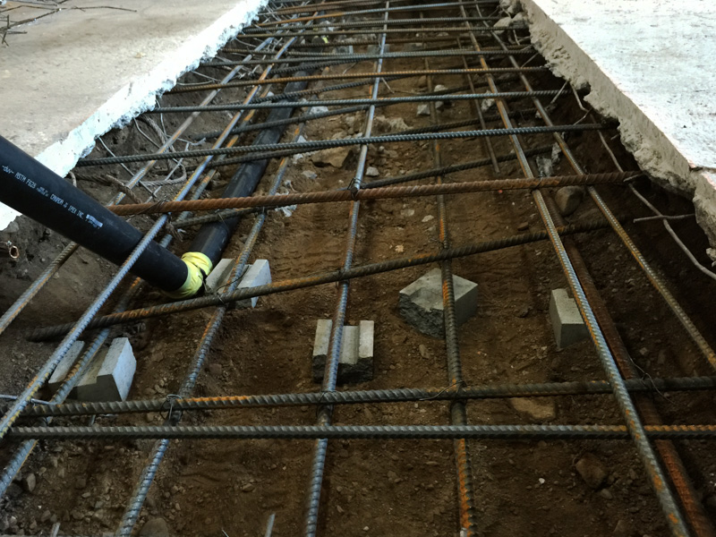
I used the Mohawk guide combined with a spec provided by the engineer at the local rebar supplier. I used epoxy anchors due to all the issues folks have had with the wedge type. The black ABS was to route hydraulic lines under.

Sent from my SM-G920T using Tapatalk
OP
xxBotelloxx
Active member
- Joined
- Oct 31, 2014
- Messages
- 43
Did u drill holes afterwards? Thought about making plate and having it set in concrete but would be a pain if it's not square**, like this...rebar is at two "elevations in the slab. This slab spec I used for for a 7000lb Mohawk asym. So you'd need to reference the pdf I linked to.
I used the Mohawk guide combined with a spec provided by the engineer at the local rebar supplier. I used epoxy anchors due to all the issues folks have had with the wedge type. The black ABS was to route hydraulic lines under.
Sent from my SM-G920T using Tapatalk
OP
xxBotelloxx
Active member
- Joined
- Oct 31, 2014
- Messages
- 43
Concrete poured 12-10-14another factor is how long did you allow the concrete to cure before installing the lift
Lift installed 01-16-15
Sent from my SM-G920T using Tapatalk
laser3kw
Well-known member
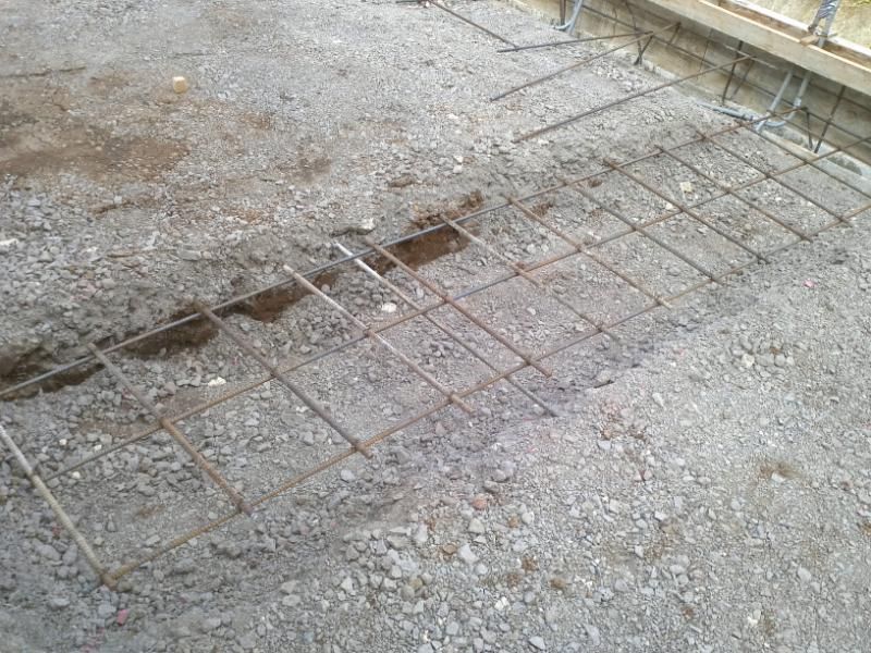
take note of Denwoods install. There are a lot of details such as rebar running in three directions (90º & at angles) and the way the dirt is removed to undercut the original slab. Also take note of the bottom of the original slab. That shows how inconsistent the slab thickness can be.
That a good retro slab modification.
That a good retro slab modification.
Last edited:
David C
Well-known member
The cross section detail in Mowhawks recommended pad footing shows clearance of the bottom bar to soil as 3/4" to 1-1/4". ACI requires 3" clear of bars to soil for cast in place concrete.
The ACI document is adopted by all of the building codes I am familiar with. The Mowhawk detail does not comply with code.
Denwood's photo shows the bars in the reinforcement matts embed or touching soil. The bar ends must comply with the same 3" clearance to soil as well, per code.
I don't know why Mowhawk would show only the one matt of reinforcing. When the lift is used there is a bending moment applied to the concrete footing creating tension at the top of the footing on one side (of the column), and tension on the bottom of the footing on the other. Denwood was wise to place two matts of reinforcing. In the future, when placing bar, he should consult the bar clearances required by code.
Note that the Mowhawk recommended wedge anchor bolt has an ESR report and the minimum depth of embedment is less than the minimum slab or footing thickness. Not also that the Wejit 3/4" AB would not work (comply with code) in the OP's thin slab, same as all other AB's.
xxBotell- If you are afraid that tightening your anchor bolt will do more damage; what do you think will happen when your lift puts a tension force on the same AB, with you under the elevated vehicle?
Denwood
Well-known member
Thanks laser ") My own retro slab was very much overkill for the Maxjax, however I like a margin of safety when it comes to working under s vehicle
My own retro slab was very much overkill for the Maxjax, however I like a margin of safety when it comes to working under s vehicle
**, I drilled after. Nice thing about a retro slab is that you can plan and make sure rebar is outside of the hole locations. Much easier/faster than plates. If you wait a few days after, the holes go quick. I waited 2 wks before installing the epoxy anchors.
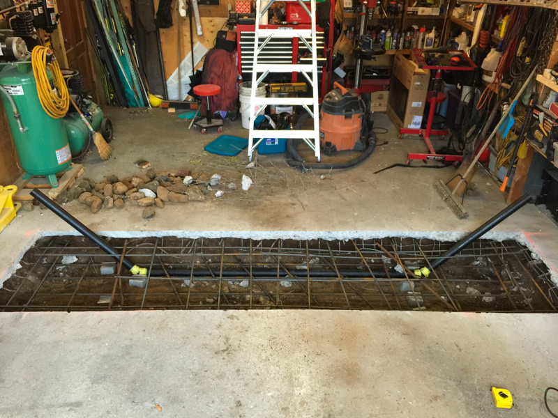
On the settling issue, don't worry about it unless you are disturbing soil below the retro slab level. My retro slab section is about 6000lbs. A year later after a brutal winter (temps below -35C) with slab temps below zero (shop only heated when in use), zero cracks and zero settling. You can pin your retro into existing, or do the 6" undercut like I did.
From my slab pour thread: http://www.garagejournal.com/forum/showthread.php?t=265806
David, the bottom layer of reinforcement was elevated 3.5 inches using the concrete stand off blocks spec'd for this purpose. These bits were advised by the engineer at Harris rebar. They spec'd and precut everything for me.
My own retro slab was very much overkill for the Maxjax, however I like a margin of safety when it comes to working under s vehicle **, I drilled after. Nice thing about a retro slab is that you can plan and make sure rebar is outside of the hole locations. Much easier/faster than plates. If you wait a few days after, the holes go quick. I waited 2 wks before installing the epoxy anchors.
On the settling issue, don't worry about it unless you are disturbing soil below the retro slab level. My retro slab section is about 6000lbs. A year later after a brutal winter (temps below -35C) with slab temps below zero (shop only heated when in use), zero cracks and zero settling. You can pin your retro into existing, or do the 6" undercut like I did.
From my slab pour thread: http://www.garagejournal.com/forum/showthread.php?t=265806
..soil estimate (undisturbed is 1500lbs/square foot...
...
Bob, I used the A7 lift retrofit spec. for a few reasons:
1. It is a 72" lift vs the MaxJax at 48". The lever forces would likely be up to 50% more than the MaxJax.
2. The A7 is asymmetric, with max load 7000lbs, so would need to withstand much more forward loading than the Maxjax.
The slab I'm about to pour (144"x48"x14") requires 1.9 cubic yards of concrete, with a weight of ~6960 lbs. I've cut a 36" wide slot, but the slab will actually be 48" wide with the key-in. The soil underneath is undisturbed, and consists of fist sized boulders and compact earth...it's a beast to dig up. Bob is telling me 1500lbs/square foot would be a typical number to calculate support for this soil type. With a slab, just sitting there (no key in to existing), it would require upwards of 3480 lbs (half the slab weight) to tilt the slab. With the MaxJax columns in the middle of the slab, (assuming a simple lever) it would require an imbalance of 994lbs, 7ft away, to tilt the slab. In other words, if I balanced a car on the hoist, then hung 1000lbs from on one bumper, I'd just tip my slab...assuming zero key under existing. Given the 6" key in, and 4x4 mesh reinforcing at the edges that I'll be tying into, I'd have to estimate several thousand pounds to break out the reinforced edge, maybe more. I'd be pretty confident saying that it would take over 2000lbs, 7ft away to tilt the slab with key in.
Feel free to check my math...just did some simple calcs
David, the bottom layer of reinforcement was elevated 3.5 inches using the concrete stand off blocks spec'd for this purpose. These bits were advised by the engineer at Harris rebar. They spec'd and precut everything for me.
Last edited:
OP
xxBotelloxx
Active member
- Joined
- Oct 31, 2014
- Messages
- 43
Talked with concrete contractor today, he gonna come look at it and said concrete will need to be cut out and reinforced, kind of seems like he is blaming me without saying so directly. He said concrete was not reinforced because I said it would be about center of shop. Well after measuring it is center where the footing (if that's right term for cross in middle) is supposed to be.
Sent from my SM-G920T using Tapatalk
Sent from my SM-G920T using Tapatalk
OP
xxBotelloxx
Active member
- Joined
- Oct 31, 2014
- Messages
- 43
Kind of lost on what needs to be done. I'm guessing 4 x 12 cut out 12 inches deep. Rebar 3 inches off dirt with another layer of Rebar somewhere above tie in to existing slab?
Does top n Bottom Rebar sections need to be tied together?
Does it help to add gravel? Sorry for my ignorance I don't have a clue What's best and don't wanna get jerked around after dropping 30k on shop.
Sent from my SM-G920T using Tapatalk
Does top n Bottom Rebar sections need to be tied together?
Does it help to add gravel? Sorry for my ignorance I don't have a clue What's best and don't wanna get jerked around after dropping 30k on shop.
Sent from my SM-G920T using Tapatalk
OP
xxBotelloxx
Active member
- Joined
- Oct 31, 2014
- Messages
- 43
Would I be able to reuse the 3/4 anchors if I can get them out of busted concrete
Sent from my SM-G920T using Tapatalk
Sent from my SM-G920T using Tapatalk
OP
xxBotelloxx
Active member
- Joined
- Oct 31, 2014
- Messages
- 43
Increase what to 4000 or 5000
Sent from my SM-G920T using Tapatalk
Sent from my SM-G920T using Tapatalk
motofool33
Well-known member
The concrete psi rating
Sent from my SAMSUNG-SM-G900A using Tapatalk
Sent from my SAMSUNG-SM-G900A using Tapatalk
OP
xxBotelloxx
Active member
- Joined
- Oct 31, 2014
- Messages
- 43
How is that figured I know lift required 3000 or 3500
Sent from my SM-G920T using Tapatalk
Sent from my SM-G920T using Tapatalk
motofool33
Well-known member
As I understand it's the composition of the concrete ordered/mixed that way to achieve the strength
Sent from my SAMSUNG-SM-G900A using Tapatalk
Sent from my SAMSUNG-SM-G900A using Tapatalk
OP
xxBotelloxx
Active member
- Joined
- Oct 31, 2014
- Messages
- 43
Well I be glad to get it covered under warranty. If I gotta pay then I will have do it the best way
Sent from my SM-G920T using Tapatalk
Sent from my SM-G920T using Tapatalk
laser3kw
Well-known member
take a look at this post:
GJ post about concrete link
Has some interesting facts about concrete strength and water addition.
FYI, just some good reading about how concrete develops strength.
GJ post about concrete link
Has some interesting facts about concrete strength and water addition.
FYI, just some good reading about how concrete develops strength.
lakeroadster
Well-known member
So you called the guy that poured the concrete, and he said replace it without even looking at it? Yeah.. that's not surprising.
I'd suggest you get a second opinion, from somebody that doesn't have skin in the game. Like a structural engineer, somebody with credentials that designs based on what the actual conditions are now, and what the actual loading is based on your application.
As for the link that was posted for a retrofit slab, that's great information. However it doesn't apply to your current installation. Apples and Oranges.
You may find you can redrill the one bad AB hole and install one epoxy anchor, install grouting under the columns and be done.
Last edited:
David C
Well-known member
OP
Talked with concrete contractor today, he gonna come look at it and said concrete will need to be cut out and reinforced, kind of seems like he is blaming me without saying so directly.
Blaming someone else is typical, a universal contractor reaction to problems. With that said you are probably going to have to spend more of your own money. If you want to get into the argument business, not recommended, you can measure your slab thickness, after it is saw cut, and show him where it deviates from what you specified.
Kind of lost on what needs to be done. I'm guessing 4 x 12 cut out 12 inches deep. Rebar 3 inches off dirt with another layer of Rebar somewhere above tie in to existing slab?
Does top n Bottom Rebar sections need to be tied together?
Does it help to add gravel? Sorry for my ignorance I don't have a clue What's best and don't wanna get jerked around after dropping 30k on shop.
You need to get professional advice. They way I have designed footings below lifts is to obtain the specific lift design. Calculate the maximum forces on the pad footing by assuming the max allowed vehicle weight, extended at the max allowed arm distance, and impose any code specified lateral loads on the suspended vehicle and lift. This determines the footing loads. Then use a the code min soil bearing (sometimes 1000PSF) or a higher value from a geotechnical report, to calculate the footing size, thickness, reinforcing, and anchor bolt attachments.
You probably will not need shear reinforcing so you do not need to connect top and bottom reinforcing matts, however comply with the requirements of your design. When placing the specified reinforcing maintain required bar clearance to soil, and to the top of the slab; these are different distances.
Do not let your bars touch soil as shown in Dennis's photos. Do not place bars at angles to each other (bars should be perpendicular) as this will create a weaker footing, in one loading axis.
Obtain and place the concrete with the compressive strength specified by your designer. It is not neccessary to create a design that uses higher compressive stength concrete, such as 4ksi or 5ksi. Codes very on how these higher values must be verified. Just because you order 5ksi concrete does not mean that you will get 5ksi concrete. If your design is based upon the higher strength, and you don't get it, you have a weaker footing.
You footings should be cast into undisturbed soil, or compacted aggregate. Get this recommendation, soil vs agg, from your designer. Compacted aggregate is sometimes used, in conjunction with a heavy visqueen layer, to prevent water wicking up into the slab.
lakeroadster
Well-known member
Repost of Link: Simpson strong-tie ® strong-bolt ® wedge anchor
Bad link.. here is the link http://www.icc-es.org/reports/pdf_files//ESR-1771.pdf
Lots of great data in the link.... my head hurts a bit.
Note the required concrete thickness based on anchor length, as David C eluded to previously. A 3/4" anchor with a 4-1/8" embedded anchor depth requires a 6-3/4" min. slab thickness.

..... See ESR 1771 http://http://www.icc-es.org/Reports/pdf_files/ESR-1771.pdf... My sole intent is to educate a few people, that ones that are going to install a new lift, to give their installation serious thought. Be safe out there.
Bad link.. here is the link http://www.icc-es.org/reports/pdf_files//ESR-1771.pdf
Lots of great data in the link.... my head hurts a bit.
Note the required concrete thickness based on anchor length, as David C eluded to previously. A 3/4" anchor with a 4-1/8" embedded anchor depth requires a 6-3/4" min. slab thickness.

Last edited:
wssix99
Well-known member
To be honest all I know is the contractor was informed I would be installing a lift, he had to follow criteria from city inspector. I've had lifts installed in buildings I've rented I've also worked in older and newer shops with lifts and never had this issue.
It is possible that you are in serious trouble here and your lift is in a dangerous situation right now. I would not let your contractor touch your building again until you know what is going on. I would also certainly not put any loads up on your lift.
Your rental installs probably went well because you didn't have the opportunity for a contractor to get confused about a new slab pour. That "cross" in your slab is most likely what is causing the crack and is creating the weakness. (Depending on where your lift is cited currently, it could roll over with a load on it.)
Confirming if you have a post-tensioned slab is important. If so, you should go no further until consulting the engineer who designed it. The cross you have in your slab looks like grade beams that would be associated with such a thing. However; it seems that you may not have a post-tensioned slab. In that case:
Kind of lost on what needs to be done. I'm guessing 4 x 12 cut out 12 inches deep. Rebar 3 inches off dirt with another layer of Rebar somewhere above tie in to existing slab?
Does top n Bottom Rebar sections need to be tied together?
Does it help to add gravel? Sorry for my ignorance I don't have a clue What's best and don't wanna get jerked around after dropping 30k on shop.
All one needs to do is follow the instructions....
For a new pad install, the manufacturers will call for a totally flat slab. No "footer," no reinforcing for strength -> nothing special. This is likely what you had in your rental units. Easy.
When people don't understand the mechanics of reinforced concrete and/or slabs, it is common to overthink the situation and assume that a "footer" is needed for something like this.
^ If your contractor assumed this, then they should go back and read the instructions. The repair will fall on them.
^ If the city inspector assumed this and called for it, then you and your contractor should get a lawyer and the inspector should be fired.
If you don't have a post-tensioned slab, then that "cross" structure, coupled with the reinforcing you do have, would create differential stresses along the "cross," which will cause shrinkage cracks to form - exactly where you do not want them. The fix would be to cut out the slab and retrofit.
The retrofit application is different. The retrofit will go as Denwood instructs, with extra depth, rebar, and either pinning or keying in to the old slab. You will also want to cut out any sections of the cross that remain in the path of your retrofit. (BTW - This retrofit looks like a "footer," but technically isn't.)
readhead
Well-known member
We really don't have enough information. It appears to be a metal building from what I could see in the pictures. If that is the case there may be rebar ties at the column piers in thickened concrete. The lift column is near the edge which may already be very thick if it is a mono pour. Do we actually know what the concrete thickness is? That would be a good place to start. Once that is known an anchor plan can be developed. Cutting out concrete at this point would be premature.
wssix99
Well-known member
The cross section detail in Mowhawks recommended pad footing shows clearance of the bottom bar to soil as 3/4" to 1-1/4". ACI requires 3" clear of bars to soil for cast in place concrete.
If you want to read ACI on this, you should look at ACI-360R. I'm not sure if the documents you are looking at are for structural members, or not, but slabs on grade are different.
In thin slabs, reinforced for crack control, it would be impossible to keep 3" clear of the soil.
The ACI document is adopted by all of the building codes I am familiar with.
Which document are you looking at? I have yet to see anything in building codes prescribing anything for garage slabs other than slope.
Reinforcing for slabs-on-grade is ONLY used for crack control. It isn't needed for strength or bending resistance except in extreme industrial applications. ACI-360R will detail this. Since the slab is continuously supported by the ground, the tensile forces from bending are greatly reduced. (Unlike an elevated beam or a grade beam seeing more concentrated loads.)
Mohawk's spec is fine.
I don't know why Mowhawk would show only the one matt of reinforcing. When the lift is used there is a bending moment applied to the concrete footing creating tension at the top of the footing on one side (of the column), and tension on the bottom of the footing on the other. Denwood was wise to place two matts of reinforcing.
Mohawk's spec (and Denwood's application) has reinforcing in place for crack control, which in these situations would (obviously) be a bad thing. It serves no structural purpose since the retrofit slab is keyed to the larger slab and the bending movements are carried by the larger slab-on-grade system.
xxBotell- If you are afraid that tightening your anchor bolt will do more damage; what do you think will happen when your lift puts a tension force on the same AB, with you under the elevated vehicle?
Right. At the point that the surface is spalling, the concrete around the anchor bolt has failed and it will never hold, unless you can put in a new bolt that will hold strong below the failure. (At a 4" thickness, I don't see that this would be possible.) I expect that this hole failed because it's so close to the crack.
Epoxy, etc. may help get the bolt up to torque, but that's no guarantee that the next layer of concrete in that area won't spall off the next time it sees a larger load.
Strouty
Well-known member
Most lift manufacturers have minimum distances that you need to keep from edges and from any seams as well.
David C
Well-known member
WSSIX, I notice from your posts that you are a nice guy so I will take a minute to respond to your comments. I can't always do this as it simply takes to much time to explain structural design, code requirements and interpretations, and the nuances of the profession.
f you want to read ACI on this, you should look at ACI-360R. I'm not sure if the documents you are looking at are for structural members, or not, but slabs on grade are different.
In thin slabs, reinforced for crack control, it would be impossible to keep 3" clear of the soil.
I've read the code more times than you have looked at the cover. ACI-318 section 7 lists bar cover requirements and for cast in place concrete it is 3" when cast against and permanently exposed to weather. What you are referring to is that for certain thin slabs on grade there is an exception. What was being discussed was the reinforcing in the detail Dennis showed and his photographs which were for pad footings. There simply is not enough time to discuss all the exceptions and permutations to structural design and codes.
Which document are you looking at? I have yet to see anything in building codes prescribing anything for garage slabs other than slope.
There is nothing in any code that says for garage slabs that have a lift you must use such and such reinforcing. What the code will say is something like this "Building, structures and parts thereof shall be designed and constructed in accordance with strength design, allowable stress design, ...etc.
ASCE 7-10 says "This standard provides minimum load requirements for the design of buildings and other structures that are subject to building code requirements.
In my own words; all structures, including the OP's garage must be designed in accordance with the specified loadings (ASCE 7-10) and rational structural methods.
I don't have time to walk you through the IBC and various state amendments, the reference in these codes to ACI-318 and ASCE 7-10, or for that matter the reference to AISC for steel, and the NDS for wood design. If you don't believe me you will have to research this on your own.
Mohawk's spec is fine.
You might be correct but that's kind of big statement there. In your structural designs for the Mowhawk lift did you account for overturning forces from eccentric column loading and seismic loads?
Mohawk's spec (and Denwood's application) has reinforcing in place for crack control, which in these situations would (obviously) be a bad thing.
I don't understand this. From what I could see he added a reinforcing mat to the top of his footing which would make his installation stronger. What he should have corrected was burying his bar ends into soil and not placing his reinforcing at 90 deg. I don't see a "bad thing".
What you may not have read in previous posts is that Mowhawk, Bendpak, and all the other lift mfgs state, unequivocally, that you must comply with local codes. Current local codes for most, if not all, of the US require specific slab or pad footing thicknesses that will accept a 3/4" anchor bolt. This concrete thickness is always greater than 5". A lightly reinforced 4" slab on grade is probably not sufficient to support and brace a loaded lift.
I don't have the time to research it but I believe there are code requirements for designing footings under point loads and column loads. A 4" slab on grade is not a footing.
If you have a failure because you installed a lift on a 4" slab with 3/4" wedge anchors, even though the mfg said it was OK, their attorneys will say that you did not follow requirements which is to comply with current codes.
The lift mfg's are (way) behind current codes. In my view they are at risk for showing designs that do not comply with the codes in the US.
If the OP slops some epoxy into his enlargened hole, in his thin concrete, he will not have complied with code. Epoxy may not provide the required connection design strength. No one should be suggesting that he do this.
ltusler
Well-known member
Its a symmetric lift. The weight will travel to the base assuming a equal balance of the load. I would take off the nut pound the anchor through the slab(assuming it was drilled through), install a proper epoxy anchor. You have 9 other good anchors, if you wanted to take extra precautions brace it at the top to the building structure so it can't tip. But that's just my opinion.
Commendatore
Well-known member
Brace it to the top of the building so it can't tip? Did you mean to suggest he should attach the top of the lift to the roof framing so that in the event the lift overturns the entire building comes down?
Denwood
Well-known member
The reason I ended up using Mohawk's guide is that it was one of the few I could find online from lift manufacturer.. If you check it out, there are full slab and retro pour specs for most of their lifts across the weight ranges. What I posted was only the spec for their 7000lb
http://www.mohawklifts.com/library/manuals/Slab_Require_Recommend_11_07.pdf
Maxjax posted a few calcs on their lift with respect to bolt loads: http://www.maxjaxusa.com/maxjax-how-safe
The manufacturers are suggesting 4" is ok, but as it has been pointed out, you need more depth if you work from the anchor bolt specs. The minimum depth for the Epoxy anchors I used is 6 1/4" (for a 5/8 11 thread insert with 26100 lbs tensile) . Most residential garage slabs are less than this.
http://www.toggler.com/wejit/techspecs_power_sert.html
Last edited:
lakeroadster
Well-known member
.....
There is nothing in any code that says for garage slabs that have a lift you must use such and such reinforcing. ....
What you may not have read in previous posts is that Mowhawk, Bendpak, and all the other lift mfgs state, unequivocally, that you must comply with local codes. Current local codes for most, if not all, of the US require specific slab or pad footing thicknesses that will accept a 3/4" anchor bolt. This concrete thickness is always greater than 5". A lightly reinforced 4" slab on grade is probably not sufficient to support and brace a loaded lift.
......
If you have a failure because you installed a lift on a 4" slab with 3/4" wedge anchors, even though the mfg said it was OK, their attorneys will say that you did not follow requirements which is to comply with current codes.
The lift mfg's are (way) behind current codes. In my view they are at risk for showing designs that do not comply with the codes in the US.
If the OP slops some epoxy into his enlargened hole, in his thin concrete, he will not have complied with code. Epoxy may not provide the required connection design strength. No one should be suggesting that he do this.
I just received a permit yesterday, and it instructs the inspector to ensure that the manufacturers specifications are followed.
So if that is the case with the OP, and I bet it is, then it was installed "per the code."
For a guy installing a lift in his garage most folks won't hire a designer for the slab. They'll do what the manufacturer specifies.
As for attorneys.... even God couldn't design them out of the equation.
_____
John
Last edited:
David C
Well-known member
I just received a permit yesterday, and it instructs the inspector to ensure that the manufacturers specifications are followed.
You have made an erroneous assumption.
So if that is the case with the OP, and I bet it is, then it was installed "per the code."
Not true, his AB's are not installed correctly. His slab is not thick enough. Possibly his slab structural design is not sufficient.
For a guy installing a lift in his garage most folks won't hire a designer for the slab. They'll do what the manufacturer specifies.
I agree. Which is why I have spent the time to explain why this might not be a good idea. Note that Mowhawk provides the pad footing detail shown in one of Dennis's posts. In my view the other lift mfg's are at risk.
As for attorneys.... even God couldn't design them out of the equation.
Can't be argued but what I would add is you neglected to consider the client. Attack dogs wouldn't exist if no one wanted them.
lakeroadster
Well-known member
I just received a permit yesterday, and it instructs the inspector to ensure that the manufacturers specifications are followed.
You have made an erroneous assumption.
So if that is the case with the OP, and I bet it is, then it was installed "per the code."
Not true, his AB's are not installed correctly. His slab is not thick enough. Possibly his slab structural design is not sufficient.
.
What "erroneous assumption" have I made?
Your assumption is the OP used anchor bolts (AB) that match the specification you referred to.
3/4 anchors where included with my lift instructions state torque to 130 ft lbs which I did few weeks ago after seeing someone drop a truck.
You are introducing specifications (The Simpson AB Evaluation Data) into this discussion that may or may not be applicable.
An Inspector is tasked with inspecting per the applicable code of construction.
_____
John
Last edited:
I believe it is a matter of implied precedence...a "nuance" as David has stated. The building code does not cover lift installation, thus permitting can invoke the manufacturer's requirements <specific to the lift>. But the manufacturers also defer to the building code as applicable, since it would be too much work to certify their instructions meet all local building codes (can you imagine what that would cost, even if it were possible?).
If 2 requirements are different, you must meet the more stringent one. If they directly conflict with one another, I would make a judgement call. In most cases, I'm guessing I would side with the building code. Drilling holes all the way through the slab is a perfect example. I understand they might be recommended by the manufacturer, as they are convenient for removal, but there are very good reasons why you shouldn't do this (as the code states) which trump convenience.
If 2 requirements are different, you must meet the more stringent one. If they directly conflict with one another, I would make a judgement call. In most cases, I'm guessing I would side with the building code. Drilling holes all the way through the slab is a perfect example. I understand they might be recommended by the manufacturer, as they are convenient for removal, but there are very good reasons why you shouldn't do this (as the code states) which trump convenience.
wssix99
Well-known member
The lift mfg's are (way) behind current codes. In my view they are at risk for showing designs that do not comply with the codes in the US.
It seems that all of the lift manufacturers' engineers have you outnumbered on this topic. To keep insisting that your posts on this topic are correct in the face of such overwhelming evidence to the contrary are dangerously arrogant, bordering on troll-like.
I don't have the time to research it but I believe there are code requirements for designing footings under point loads and column loads. A 4" slab on grade is not a footing.
If you don't have time to research what you are posting about, particularly if you are going to make statements calling out every equipment manufacturer as being non-compliant with code, putting those opinions out there may not be such a good idea.
If you want to change course, take a step back, and reflect on this more you should re-frame your thinking of the situation:
A lift post is not a structural column. It is a piece of equipment, made by an equipment manufacturer, governed by codes relating to the install of equipment, made with an over-sized baseplate typical of a piece of equipment, (not a column) and light enough that a footer isn't even close to being useful or required. (The math to figure this out is really really simple.)
INTMD8
Well-known member
If you have a failure because you installed a lift on a 4" slab with 3/4" wedge anchors, even though the mfg said it was OK, their attorneys will say that you did not follow requirements which is to comply with current codes.
I may have missed it, but do you know the reason why 4" is not thick enough for a 3/4 anchor? (I see that's what their chart says, just curious of the technical explanation).
When I installed mine I broke through in a few holes at 4". 3/4 anchor tapped in, torqued to 110ft/lbs and didn't pull up at all. (maybe 2 threads showing above the nut).
Even with a deeper hole/thicker concrete (as it was on the post opposite) it would have torqued to the same relative position in terms of the top of the anchor to the top surface of the concrete so why is more thickness a requirement?
David C
Well-known member
Lakeroadster
I don't like being argumentative, so I am apologizing in advance for using your email to explain some concepts that don't seem to be readily understood.
I thought your assumption was that because a permit was obtained, and a building dept inspection was performed, that the design and installation conformed to code. If I made an incorrect assumption about what you were saying, I apologize, again.
Think of it this way:
If you robbed a bank and the police didn't catch you, you would have still broken the law.
If you didn't comply with code, and the building dept didn't catch you, you would still have broken the law.
When you sign your building permit you are taking responsibility for your design and that it complies with code. If your design professional signs the plans then they are responsible for the design complying with code. The building department is never, legally, responsible for code compliance.
Daedalus did a better job than I did of explaining one of my points. Thanks for that.
Mr. Wssix,
Please consider the following response:
It seems that all of the lift manufacturers' engineers have you outnumbered on this topic.
Did you see any engineering stamps on the lift mfgs recommendations? They may have me outnumbered but unless they are legally an engineer and put their license on the line, I believe they have little legitimate standing in this argument. If these engineers would state in writing that their design complies with (any) code, and stamp their design, then you would have a point. When they say that the installation has to comply with code they are opting out of the discussion.
To keep insisting that your posts on this topic are correct in the face of such overwhelming evidence to the contrary are dangerously arrogant, bordering on troll-like.
Are you saying I am a troll because I don't agree with you? I gave you the codes, I listed some of the reasons why the lift mfgs designs don't comply with codes. What's troll like in this? Wssix, I backed everything I said with references, why wouldn't you do the same
If you don't have time to research what you are posting about
I thought I did explain about the anchor bolts with a lot of references. Maybe you didn't read it. Paraphrasing you; why don't you read ACI-318 appendix D regarding concrete anchor bolts. (appendix D is appox 30 pages of complex analysis and code requirement,; read that, with comprehension, and then we can discuss this further). I'll scan it for you but I am pretty sure you won't take the time read it, let alone understand it. Really, ask me to scan it, give me a place to email the scan.
What I don't have time for is explaining to you the code, and what the processes of structural engineering are. I also think you are being hypocritical in your accusation. If you have a legitimate disagreement, post the code or it's reference, state why you disagree. SE's do this all the time when discussing design and codes, what we don't do is accuse each other of being trolls or arrogant.
David C
Well-known member
INTMD8
I may have missed it, but do you know the reason why 4" is not thick enough for a 3/4 anchor? (I see that's what their chart says, just curious of the technical explanation).
I don't have a definitive answer for your question. I have asked several AB mfgs, and the following is a shortened version of what I got from the mfg's engineers combined with information I have gotten from other sources.
Two code cycles ago the IBC, and all related codes, referenced ACI-318 appendix D for concrete AB design. This appendix is too complicated to go into and I wouldn't do it service anyway, but in short Appendix D, and it's requirements, were intended to address deficiencies in previous concrete AB design. Additionally the code required ESR reports for individual types of mfg'd AB's. Cast in place headed anchor bolt design had to comply with design procedures described in App D. The mfg'd AB had to comply with App D and add'l testing requirements which are reported in ESR reports.
The testing requirements are rigorous and comprehensive and they had to include many considerations such as edge distance, end distance to conc, C to C spacing, concrete compressive strength, AB steel strength. reinforcing under AB's and other factors. This is a lot of combinations and permutations; and expense.
For this reason (time and expense) they probably did not test every conceivable depth or situation. Or maybe they felt that the 4" - failure cone size (tension capacity) was not of sufficient magnitude to bother testing 3/4" AB's in 4" concrete when a 3/8" AB would suffice. I do not know this, it is just my opinion per what I said above.
It has long been considered in the profession that punched through holes for AB's do not, in general, provide adequate and repeatable performance. Punched through holes make it difficult to set the wedge in the AB during installation. It is important that the wedge be set (fixed) near the bottom of the hole. If it is set at mid depth you would get considerably less AB capacity. In the bottomless hole the wedge depth would be altered by the installer to get it to grip.
For chemical anchors It can't be certain that the chemical would not drain out the bottom of the hole. Again fixity is important at the max depth below the surface. (more on this later).
The mfgs, I think, did not bother testing for the drilled through condition and thus it is precluded from application.
To go further with your inquiry would require a long (or many long) conversations with someone in these companies that makes the decisions and was instrumental in the testing. I am not that guy.
For what it is worth, a lot of AB's have been installed in punched through holes, when the special inspector wasn't looking, and they have not, that I am aware of, had a high rate of failure however these connections may not provide full design capacity for the reasons noted below.
Even with a deeper hole/thicker concrete (as it was on the post opposite) it would have torqued to the same relative position in terms of the top of the anchor to the top surface of the concrete so why is more thickness a requirement?
You may not be understanding how the wedge anchors work. With the AB in tension the embeded wedge applies a force to the concrete below the surface. The strength of the connection (for a single AB) is based upon the depth of this fixity to concrete. The failure mode is typically thought of as an inverted cone with the apex at the wedge and the larger dia at the surface. The capacity of the connection is based upon the cone surface area. In your minds eye can you picture the wedge close to the surface and "see" a small inverted cone?
The capacity of the AB is not based upon the dimension you suggested, but the depth of the wedge fixity below the concrete surface. To explain the complexity of AB design consider the failure cone truncated by proximity to a concrete edge or a slab construction joint, a thiner section of slab, or other AB's. There is more but I edited it out.
With that said I will add to the mix that these tables are published with the caveat that they are provided for reference only and not to be used when designing AB connections. The actual design requirements are almost too much for hand calculations and the mfg's provide proprietary computer programs. This is the only way to design post installed AB's.
You can use the tables, the ones I have referenced, but their use does not comply with code. Generally within the profession, at least in my experience, for light loads, say attaching light wt equipment to slabs it is generally accepted, that the tables can be used. For larger loads such as the design of non building, cantilever column structures, such as these lifts, I am not sure that the tables should be used. It might also be that the actual computer calculations would not accept a 3/4" AB in a 4-3/4" thick slab even though it is listed in the table. A deeper EMB would likely be required. In summary using the published tables, in the ESR report is not approved by the mfg. And while a table value might show adequate capacity the actual computer calculation might not.
If you read in an above post WSSIX does not agree with the use of term "column" when describing these lifts, but he must be unaware of ASCE 7-05 non building structures, and also not understand what a cantilevered column is. The reason I even bring this up is that these lift columns, with their more substantial loads, and potential harm from failure probably should be designed with the mfg's computer programs and include a pad footing. I have never been able to get anything but a 3/8' (or 1/4") dia post installed AB to calculate in a 4" slab on grade; wedge, epoxy, acrylic.
Hope that helps
Last edited:
OP
xxBotelloxx
Active member
- Joined
- Oct 31, 2014
- Messages
- 43
All my bolts torqued fine.I may have missed it, but do you know the reason why 4" is not thick enough for a 3/4 anchor? (I see that's what their chart says, just curious of the technical explanation).
When I installed mine I broke through in a few holes at 4". 3/4 anchor tapped in, torqued to 110ft/lbs and didn't pull up at all. (maybe 2 threads showing above the nut).
Even with a deeper hole/thicker concrete (as it was on the post opposite) it would have torqued to the same relative position in terms of the top of the anchor to the top surface of the concrete so why is more thickness a requirement?
Not all bolts went thru conctete I don't remember exactly but pretty sure I marked bit at 4 or 4.5 inches and maybe 2 or 3 went into sand
Sent from my SM-G920T using Tapatalk