To avoid these ads, REGISTER NOW!

Wiring new Champion Compressor

Crank1

Well-known member
Joined
Jul 20, 2007
Messages
277
Hello everyone,

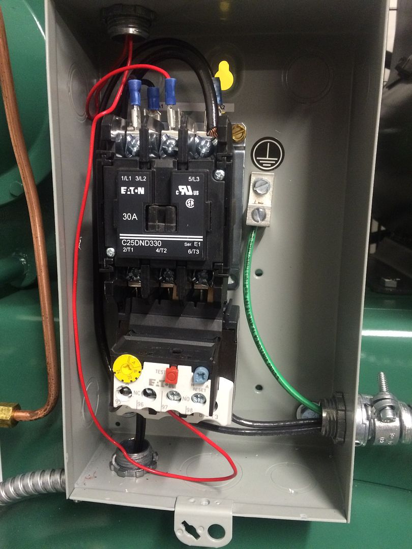
I just bought a new 80 gallon vertical compressor for Champion, I have an older one I was going to rebuild but I took the easy way out. So now I have this thing leveled, and isolated and located in its resting place, I just have to wire it up to make her hum. Here is where I am requesting help, the motor is a 5 hp Baldor single phase, with an Eaton mag starter, and it is wired to the plug with 10-2 wire I believe. I'm fairly sure I just hook the red and black wires to L1 and L2 for power?

http://www.mile-x.com/champion-vr5-8adv-3-ac-5-hp-3-phase-vertical-tank-air-compressor-w-air-cooled-aftercooler/

Also, I intend to run a ON/OFF Switch, its a pretty heavy duty switch, and my thought is to break the red wire running off of the pressure switch, it's a low gauge wire so I'd guess it doesn't pass much current? Any help doing that is also appreciated!


To avoid these ads, REGISTER NOW!

matt_i

Well-known member
Joined
Mar 14, 2008
Messages
10,737
Location
SE Michigan
Can't see the whole thing, what's the ********* wire going into L3 go to on the bottom side?

Also is the motor hooked to T1 and T2?

Be careful of running 220vac thru an operator station, despite the small gauge wire. Personally I try to avoid it, I'd almost rather have a neutral wire so there is free 110vac for controls...but that involves another relay, etc, etc. Make sure all metal parts of the operator switch are well grounded so there is no way it can get electrified without a dead short being developed before you become the shorting conductor.
 
OP
C

Crank1

Well-known member
Joined
Jul 20, 2007
Messages
277
By operator station are you referring to the switch? My understanding of the small gauge wire from the pressure switch is what actually closes to make the 230V circuit close?

I'll get a better pic when I leave work, but yes I believe the motor is hooked to T1 and T2
 

redmondjp

Well-known member
Joined
Nov 25, 2014
Messages
2,318
Location
Redmond, WA
Can't see the whole thing, what's the ********* wire going into L3 go to on the bottom side?

Also is the motor hooked to T1 and T2?

Be careful of running 220vac thru an operator station, despite the small gauge wire. Personally I try to avoid it, I'd almost rather have a neutral wire so there is free 110vac for controls...but that involves another relay, etc, etc. Make sure all metal parts of the operator switch are well grounded so there is no way it can get electrified without a dead short being developed before you become the shorting conductor.

Why are you saying this? There is absolutely no additional danger from 220V control voltages (actually 230-240V typical) over 120V, as the potential from either L1 or L2 to ground is the same: 120VAC.
 

matt_i

Well-known member
Joined
Mar 14, 2008
Messages
10,737
Location
SE Michigan
Its a good point but if you make a mistake and get between the hot legs you can die pretty fast. 110vac will obviously shock you and hurt you but likely not stop your heart unless you get to the point where your muscles can't fire because of the overtrumping AC.

There's a whole set of industrial electrical rules that govern voltages greater than 50v (ac or dc) for such reasons. You don't have to be compliant in your own garage but the standards and rules are put there for reasons and not for idle whim.
 

Tim65GT

Active member
Joined
Mar 26, 2015
Messages
40
The link you posted is for a 3 phase motor??? The switch you want to use should work. You will only use one pole of it to interrupt the Pressure Switch circuit (small red wire).
 

gregtwojeeps

Well-known member
Joined
Jul 30, 2013
Messages
5,096
Location
Ky
From the looks of what I can make out on the starter wiring, and if I am seeing the conductors correctly the larger conductors being the motor wires are entering the starter box from the bottom right side...and the incoming main power wires are entering the box in on the bottom left of the box .....

I hope he does not try to run the motor the way it is wired. I see no motor leads running through adjustable trip current sensing heater block . There are wires on top of the starter it appears to me though, are they the main power ? It is a 3 phase starter yet the OP states his unit is a single phase. Single phase connections will work on a single phase starter but power in needs to be on L1 and L2 and motor leads needs to be on T1 and T2. Maybe I am just seeing it all wrong though ? . JMO
 
Last edited:

LS6 Tommy

Well-known member
Joined
Dec 27, 2013
Messages
26,162
Location
Northern NJ
Its a good point but if you make a mistake and get between the hot legs you can die pretty fast. 110vac will obviously shock you and hurt you but likely not stop your heart unless you get to the point where your muscles can't fire because of the overtrumping AC.

There's a whole set of industrial electrical rules that govern voltages greater than 50v (ac or dc) for such reasons. You don't have to be compliant in your own garage but the standards and rules are put there for reasons and not for idle whim.


The difference in the chance of being killed by 120VAC or 230VAC is very little. As long as the potential is enough to overcome the resistance of your skin, current is what kills you. 1/10A will stop your heart if it's applied directly. If you grab both hot and neutral on a 120V circuit or both hots on a 230V circuit, you have pretty much the same chance of getting dead. The reason high voltages (600 or more) are more dangerous is because the higher voltage breaks down the skin resistance and allows greater current flow. It also is much more likely to cause extensive tissue damage, so even if you don't go into cardiac arrest, you're chances of survival are reduced.


Tommy
 

LS6 Tommy

Well-known member
Joined
Dec 27, 2013
Messages
26,162
Location
Northern NJ
Crank, the link you posted specs out for a 3 phase unit. I hope that's just a mistake. Can you post some more pics of the starter & the motor diagram label? From what I can see, if the motor and starter came wired from the factory, you should be good to go by bringing your feeds to L1 and L2 on the starter.

Tommy
 
OP
C

Crank1

Well-known member
Joined
Jul 20, 2007
Messages
277
I managed to get the compressor wired to power and have been using it. Kinda just went for it with the little I know.

So just looking, the small gauge red wire, looks to be the low oil shut off switch, and this smaller black 12 gauge wire goes over to the pressure switch; I was hoping I could just break this wire using the switch I have. Would it matter which side of the pressure switch I install the switch on?


myredracer

Well-known member
Joined
Nov 1, 2015
Messages
557
Location
Langley, BC
Why is there a neutral wire in there and why is it being run through the contactor? Or it's not a neutral and you are using the 3rd pole to control something? Only getting partial glimpses of the overall picture it seems.
 
Last edited:
OP
C

Crank1

Well-known member
Joined
Jul 20, 2007
Messages
277
Are you talking about the large gauge black wire? I believe it's fed from the T2 and back around to the L3

The 2 wires I'm questioning whether I can install the switch on enter the box from the pressure switch, where you see my finger, then connect on the spade terminals at A1 and A2
 
To avoid these ads, REGISTER NOW!

52wrench

Well-known member
Joined
Dec 20, 2015
Messages
69
Location
western NYS, land of taxes
" Why is there a neutral wire in there and why is it being run through the contactor??? Only getting partial glimpses of the overall picture it seems"

x2. Three pole contactor used for 230 single phase is fine but where does that white wire connect at the breaker box??? How many wires did you run from the box, should be two hots and a ground. Re. the switch, you usually install any disconnects before any other devices.
 

52wrench

Well-known member
Joined
Dec 20, 2015
Messages
69
Location
western NYS, land of taxes
Looks like he used a white wire for a hot, that is not good, should be two blacks and a ground. It will work fine but has the potential to kill someone later on who mistakes it for a neutral if they don't check it first.
 
OP
C

Crank1

Well-known member
Joined
Jul 20, 2007
Messages
277
I believe the white and black are both hot and the green is ground. The panel is only 15 feet from the compressor. I'm not necessarily looking to isolate power for security and maintenance, but to keep the compressor from kicking on in the middle of the night. My understanding is that the pressure switch wire is what controls the contractor, so if I break that with a switch, I can keep it from kicking on. I don't want to flip a breaker every time.
 

Norcal

Well-known member
Joined
Mar 16, 2008
Messages
13,767
Looks like he used a white wire for a hot, that is not good, should be two blacks and a ground. It will work fine but has the potential to kill someone later on who mistakes it for a neutral if they don't check it first.

IF it is part of a cable assembly such as MC cable, it is permitted to re-identify a white conductor, but can't be done with single conductors in conduit.
 
OP
C

Crank1

Well-known member
Joined
Jul 20, 2007
Messages
277
It was a pre-wired piece of conduit. I suppose that is the MC cable?
 

52wrench

Well-known member
Joined
Dec 20, 2015
Messages
69
Location
western NYS, land of taxes
IF it is part of a cable assembly such as MC cable, it is permitted to re-identify a white conductor, but can't be done with single conductors in conduit.


Agree, just question now many of these set ups gets reidentified correctly? Anyone knowing what they are doing is going to check it first but the guy who is not familiar may just assume it's neutral.
 

matt_i

Well-known member
Joined
Mar 14, 2008
Messages
10,737
Location
SE Michigan
The A1 - A2 is the coil that operates the contacts associated with L1,L2,L3. You break into that circuit, you inhibit the contactor (iow coil circuit cannot be completed to energize & close the contacts) or allow the pressure switch to make decisions (iow allow coil circuit to be completed by normal means, the pressure switch and motor overload are the elements which can inhibit the coil).
 
OP
C

Crank1

Well-known member
Joined
Jul 20, 2007
Messages
277
Re-identify how? I am the only one working on my stuff and I know(barely) enough to isolate power before working.
 
OP
C

Crank1

Well-known member
Joined
Jul 20, 2007
Messages
277
The A1 - A2 is the coil that operates the contacts associated with L1,L2,L3. You break into that circuit, you inhibit the contactor or allow the pressure switch to make decisions.

Thanks for this! This was my thought and just wanted a little backup!
 

52wrench

Well-known member
Joined
Dec 20, 2015
Messages
69
Location
western NYS, land of taxes
Take a black sharpie and color the white black at the contactor and the breaker. If you're going to do your own electrical at least get a good book and read about the practices, theory, codes, etc.
 
To avoid these ads, REGISTER NOW!
Top Bottom