To avoid these ads, REGISTER NOW!

A Watts linkage alternative

Techie1961

Well-known member
Joined
Feb 18, 2014
Messages
1,520
Location
Pickering Ontario Canada
Many years ago I built a pickup truck into a Pro Street version. I wanted a 4 Link at the time but couldn't manage the cost at the time so I picked up a pair of Competition Engineering ladder bars and built the rest of the suspension myself. Part of what I wanted was Koni coilovers as well and when you do that, you need a Watts linkage or single cross link.

I didn't like those since both have issues. A cross link will cause the rear end to move in a radius and not track straight. A Watts linkage is much better but during cornering, it will try to centre itself height wise.

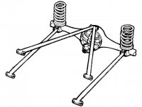
I designed and built this system for the truck and had it on the road for quite a few years and raced it as well. I had quite a few hours on highways and drove to shows and races in the USA. I don't know if it's something that anyone can use but feel free to go ahead if it serves your purposes.

You can kind of see it in this shot. There are two bars with Heim ends at each end that are attached to the outer portion of the rear end and the other ends meet in the centre that is about 3 feet back. They are attached to a swinging shackle that raises and lowers with the suspension. Since it fully triangulates the rear end and moves up and down with it, it is very stable on the highway.
3081427884_f921f1c1e8_b.jpg


In this photo, you can see the shackle that I built. It's riding on needle bearings.
3081411700_033aa04cfa_b.jpg
 
To avoid these ads, REGISTER NOW!

kerrynzl

Well-known member
Joined
Nov 8, 2013
Messages
5,054
Location
Tauranga, New Zealand
A Watts linkage is much better but during cornering, it will try to centre itself height wise.

Explain your theory on this..

A watts doesn't alter ride height during lateral acceleration, that is usually the function of roll centre height in relation to centre of gravity height'

Are you still running the parallel ladder bars on the street?
 

astroracer

Well-known member
Joined
Jun 22, 2005
Messages
3,001
Location
Mid_Michigan
Boy... I guess I'll have to take you at your word on how it handles but, to me, that is scary.
Panhard bars work well but you have to make them as long as possible to keep housing migration to a minimum during jounce/rebound. They also work well to locate the housing side to side in the vehicle as they create a straight line link from the housing to the frame rail.
What you have built here really does nothing to control the axle in the cross car direction. That long reach to the back actually creates a huge swing arm. The center of the swing is at the shackle you built and the outer radius goes through the hiem ends on your ladder bar mounts.
The only factor that keeps your housing "centered" in the truck is binding of the four link joints and your locator bar.
I would really like to do a suspension study on what you have there. Can/Would you give me dimensions for the ladder bar mounts, ride height and the rear track bar points? Dimensions for your shackle will be needed also. pivot point, length, etc.
I am curious as to what the suspension articulation looks like in a side view. The housing will pivot forward around the front ladder bar mounts but what is the rear locator doing while the housing is pivoting forward? if you lay out two circles, one centered on the front bar mounts and the other centered on the rear shackle pivot point what does that intersection point look like?
Mark
 

kerrynzl

Well-known member
Joined
Nov 8, 2013
Messages
5,054
Location
Tauranga, New Zealand
^^^^ A triangulated link works successfully at controlling lateral movement. Lotus did this on the Mk1 Cortina.
The reason the OP used a shackle is there is 2 arcs opposing each other [the ladder bars forward & the triangulated link rearward.]

My biggest concern with this rear end is not the triangulated link [ that will work OK ] but the use of ladder bars.
There is no compliance in ladder bars during body roll because the rear end housing cannot twist.

With ladder bars you can simply weld 2 x diagonal braces to them and turn the rear suspension into a giant hinge [which is how they pivot anyway]
 

Attachments

  • 3 link suspension.jpg
    3 link suspension.jpg
    41.9 KB · Views: 38
OP
T

Techie1961

Well-known member
Joined
Feb 18, 2014
Messages
1,520
Location
Pickering Ontario Canada
Let's be clear here. This is not a sports car suspension; it's a way of keep a rear end centred when running either a 4-link or ladder bars. Bot of those restrain the rear end from any longitudinal rotation. The only question after that is how to keep the rear end from falling over or laterally positioned. This applies only to coilovers and some coil spring applications.

With the system that I used, there is full travel of the suspension vertically with absolutely no binding. Since there is very little rotation longitudinally (due to ladder bars or 4-links), the Heim ends will not bind. Considering leverage, the rearward placement of the shackle provides excellent centreing of the rear end housing.

I no longer have this truck since it was sold nearly 20 years ago. For a Pro Street type application, it was fantastic.
 

E.rodz

Well-known member
Joined
Nov 11, 2009
Messages
2,435
Location
st.paul MN.
please don't take this the wrong way but i think you missed the true function of a watts link or panhard bar? the whole point of a watts link or a panhard bar is to keep the rear end centered during side loads and or turning a watts link keeps the rear centered with no migration of the rear in either direction typicaly used in a road race car that requires as wide of stance as possible with no tire rubbing either way. a panhard bar does the same thing but works on an arc so the longer the bar is the lesser amount of rear migration. my Belair runs a panhard and air ride full lift the tires rub on passenger side all air dumped the rub on drivers side. but both cases the bars run parallel to the rear axle because this is where the tube or bar has the most strength. yours has the bars running with a huge leaver arm that will flex big time under hard side loads.typical in a pro street application you never have the huge side load because your not running it in a auto cross a flying through cloverleafs. will it work? obviously yes . for you application it will. however if you decided to go road racing or auto crossing and your tires were really close to you inner wheel wells you would be in trouble! a 4,500# truck could easily deflect that wish bone to the point of tire shedding. a diagonal link is all you would have needed to do the same thing. we all learn new things are whole lives and thanks for sharing your ideas and designs. don't let the response stop you from posting . keep up the fabrication and the willing desire to be different.:thumbup:
 
OP
T

Techie1961

Well-known member
Joined
Feb 18, 2014
Messages
1,520
Location
Pickering Ontario Canada
Thanks for all of the replies but please remember, I dove this for a long time and it works. I'm not sure where some of you think the sideways movement comes from and the rear end stayed centred extremely well even with reasonably aggressive cornering.

The ladder bars or 4-link create a parallelogram with the rear end and forward frame mounts. The rear end can move side to side but will always be parallel to the vehicle's transverse direction. This linkage design creates a triangle that is extremely rigid and very strong. There is no way that there will be any transverse movement of the rear end.

For there to be any movement off axis, either the front frame mounts would have to shift forward or rearward (i.e. bent or broken frame), the ladder bars or 4-links would have to compress or stretch, the triangular rear linkage would have to compress or stretch, or the shackle mount would have to tear off of the frame.

Also as a note, I had huge tires under the truck with almost no clearance and it never rubbed on the fenders or the tubs.
 
Last edited:

mustange70

Well-known member
Joined
Jul 6, 2015
Messages
121
A wishbone setup does exactly what you want (may be what you are describing, but your pictures aren't showing).
 

mustange70

Well-known member
Joined
Jul 6, 2015
Messages
121
Yep, wishbone setup, nothing new about that. Typically the double end is at the frame in front of the axle , opposite to yours, and solid mounted and only single lower links. Turns it into a nice simple 3 link.
 
To avoid these ads, REGISTER NOW!
OP
T

Techie1961

Well-known member
Joined
Feb 18, 2014
Messages
1,520
Location
Pickering Ontario Canada
Yep, wishbone setup, nothing new about that. Typically the double end is at the frame in front of the axle , opposite to yours, and solid mounted and only single lower links. Turns it into a nice simple 3 link.

I just was hoping to share it if it helped anyone and I didn't expect all of the criticism that came out. It was about mid 80s when I did it and hadn't seen it before.
 

C_F

ALLIANCE MEMBER
Joined
Jan 21, 2005
Messages
9,675
Location
Utah...SNOW BLOWS!
Well, I for one think it's a cool design. I've seen something similar used on the front end of rock crawler vehicles lately, but for me anyway, I haven't seen it used on a rear suspension. Maybe I should get out more? LOL

I also like your alternator placement. :) Got any engine bay shots of that truck?
 

Fcvapor05

Well-known member
Joined
May 4, 2014
Messages
1,079
Let's be clear here. This is not a sports car suspension; it's a way of keep a rear end centred when running either a 4-link or ladder bars. Bot of those restrain the rear end from any longitudinal rotation. The only question after that is how to keep the rear end from falling over or laterally positioned. This applies only to coilovers and some coil spring applications.

I just was hoping to share it if it helped anyone and I didn't expect all of the criticism that came out. It was about mid 80s when I did it and hadn't seen it before.

You're catching flak because the way you did this is, let's say, not ideal.

I don't doubt that the truck drove fine and handled ok- as someone else said, this concept isn't completely new.

Where you fell a little short is just the placement of pickup points. The way that your linkage is designed, the wishbone has widely space pickup points on the axle, and a single pickup point on the chassis- but the forces running through that wishbone are much greater on the chassis and than at the axle. The truck probably handled fine, but if you ever clipped a curb with it mid-corner, I suspect it would not have held up very well. The system would have been much stiffer and stronger if you'd flipped the wishbone 180 degrees and used a single point on the pumpkin and two points on the chassis. Notice that in the drawing of the Mk 1 Cortina suspension the upper wishbone is mounted to the chassis in two widely spaced locations and to the axle in one location in the center.
 
OP
T

Techie1961

Well-known member
Joined
Feb 18, 2014
Messages
1,520
Location
Pickering Ontario Canada
Well, I for one think it's a cool design. I've seen something similar used on the front end of rock crawler vehicles lately, but for me anyway, I haven't seen it used on a rear suspension. Maybe I should get out more? LOL

I also like your alternator placement. :) Got any engine bay shots of that truck?

Thanks! Here's the best shots that I had. It got a few small changes after the magazine shoots such as ConvoPro CenterLines and bigger tires as well as a different exhaust.
19512262704_e19a008f02_h.jpg
 
To avoid these ads, REGISTER NOW!
Top Bottom