To avoid these ads, REGISTER NOW!

the MODIFICATION of the air compressor

vandalthree

Member
Joined
Jul 29, 2016
Messages
23
You are correct. I would want a hose good to at least 350 deg F. Look up Eaton aeroquip hose. I forgot where I ordered mine from but I am using that hose for a compressor discharge - it's one of the applications listed in the specs for this hose. It's extruded teflon with stainless steel braid. They have hose good to 450 and 500 deg F and well beyond any pressure they would ever see.

I remember seeing places where you could have your hose made to order with crimped on fittings. There also compression type, reusable fittings, you can install yourself, swivel and diy crimp fittings.

ETA: http://www.hosewarehouse.com/aeroquip
http://hosewarehouse.com/Hydraulic/...C807-16-Aeroquip-PTFE-Hose?mfp=68-application[Hot%20Air]

How long of a run do you think you'll need to make? You don't want too much volume of hose/tube between the compressor discharge and check valve or else pump performance will suffer.
 
Last edited:
To avoid these ads, REGISTER NOW!
OP
S

sweetk30

Well-known member
Joined
Jan 2, 2011
Messages
2,306
Location
finger lakes area upstate ,ny
looking at newer units the pump/motor side to side swap is the ticket .

and as to hose discharge length trying as short as possible. prob gona be around 3ft .

new check valve is pipe thread inlet . so I would just need pipe thread ends on both of the hose and prob swivel for 1 to make install possible.

but if I spin the tank 180* and reset the pump and motor as they are I could do a straight down dump to the valve as I will be using the side port on the tank that's 3/4 thread for the check valve I purchased . the original on top of the tank is a bit small on the body to I think safely tap to 3/4 from the 1/2" pipe it is .

the top port will become my new outlet and jump directly to 3/4 to rehook back to all my shop hard lines .

unless you guys got any other idea's to toss by me .

would love to just swap out that bung up top from 1/2" to a 1" bung so I can later swap on the 10hp motor and make here the BIG pig she should be . I trust my self welding lots of stuff and have a big Lincoln power mig 216 to burn it in . but every man has his limits of what he feels safe doing . . . . and I think welding on a tank at this point is still past my safe work limits.
 
Last edited:

vandalthree

Member
Joined
Jul 29, 2016
Messages
23
..... but every man has his limits of what he feels safe doing . . . . and I think welding on a tank at this point is still past my safe work limits.

Smart thinking. No one should modify the structure of any pressure vessel - patching holes, moving/modifying bungs etc. In the the early 1900's many people were killed by exploding boilers and other pressure vessels due to a lack of engineering knowledge and data on good design for them. Even if you follow the welding codes outlined for pressure vessels by ASME there are still other factors to analyze.

In case you didn't see it the largest hose in my link, the S-16TW, has a minimum bend radius of 9 inches. Just some info for you to think about the routing.

If your drive ratio and motor selection are going to deliver in the 16-27 cfm range as mentioned I would suggest the S-12TW with an ID of 0.640", minimum bend radius of 7.5"
 
Last edited:
OP
S

sweetk30

Well-known member
Joined
Jan 2, 2011
Messages
2,306
Location
finger lakes area upstate ,ny
pumps 1" outlet and check valve is 3/4"

as it sits now outlet is pump left up top on head .

if I spun the tank 180* and put the side port directly under the outlet it could almost drop straight down in with a elbo on both out/inlets .
 

md21722

Well-known member
Joined
Nov 30, 2015
Messages
1,840
Location
Mt Juliet, TN
I would try plumbing it with what you have on the tank. 1/2" black iron will flow something like 100 CFM. Yeah the pump pulses. Sometimes they just use standard parts to save machining costs. Champion has used 3/4" for 1-7.5HP pumps since at least the 1940's. At 10 HP no pump will make more 40 CFM. Put the reducer at the tank. Keep it simple. A 5 HP draws around 110 amps at startup, a 7.5 HP draws around 180 amps at startup, and a 10 HP draws around 210 amps at startup. I hope your electrical and the transformer at the pole is up to your future plans.
 
Last edited:
OP
S

sweetk30

Well-known member
Joined
Jan 2, 2011
Messages
2,306
Location
finger lakes area upstate ,ny
got my check valves and pop off valves yesterday .

3/4" 30cfm check valve for big unit . and 1/2" 360cfm pop off valve :eek:

1/2" 20cfm check valve for little unit. and 1/8" 80cfm pop off valve .

also got my top plates today .

1/4" plate cut on flow jet . should give me the room I need to mount both better than tight package they are now.
 

Attachments

  • 0804161234a.jpg
    0804161234a.jpg
    132.3 KB · Views: 32
  • 0805161317a.jpg
    0805161317a.jpg
    130.7 KB · Views: 23

vandalthree

Member
Joined
Jul 29, 2016
Messages
23
Md do you have sources for your values on startup current? They seem high to me so I'm curious.

Locked rotor current, or startup current, is going to vary based on motor design. I have generally seen a 60 amp breaker recommended for 5 hp compressors and an 80 amp recommended for 7.5 hp. If the values were as high as you suggest I would think you have tripping issues.
 

Finky198

Well-known member
Joined
Feb 25, 2014
Messages
2,120
Location
North East
I am currently running a 50 amp for our 7.5 hp we have a 60 amp sitting on the shelf, but I see no need as it has tripped once ... our welder thats another story...

I was told you could use a breaker no higher then 150% of the motors rated load.??.
or the Mag starter?? I'm not familiar with so I can't comment.

I'm no electrician, but I would think its similar to jump packs and peak amps or Air guns and nut busting torque. its a millisecond surge of power whether electrical or mechanical... and that has to been factored into the engineering...
 
Last edited:

md21722

Well-known member
Joined
Nov 30, 2015
Messages
1,840
Location
Mt Juliet, TN
Md do you have sources for your values on startup current? They seem high to me so I'm curious.

Locked rotor current, or startup current, is going to vary based on motor design. I have generally seen a 60 amp breaker recommended for 5 hp compressors and an 80 amp recommended for 7.5 hp. If the values were as high as you suggest I would think you have tripping issues.

They are from Baldor spec sheets. Normal breakers allow the extra current for the milliseconds it takes for the pump to come up to speed. I run my 5HP's on 30A breakers without any issue, but 28A X 250% = 70A is allowed by code if everything else is right. Some compressor manufacturers will tell you to use 80A breakers for 7.5HP and 100A breakers for 10HP. I suspect to prevent customer calls about nuisance tripping in some situations.
 
Last edited:

vandalthree

Member
Joined
Jul 29, 2016
Messages
23
Thanks, md

Finky, there is no hard and fast rule for breaker size on motor operated circuits. There is a section of the NEC that lays out guidelines and parameters for how much you can upsize a breaker for a given motor. Any additional local codes I cannot speak to. My municipality follows the NEC and nothing more.
 

md21722

Well-known member
Joined
Nov 30, 2015
Messages
1,840
Location
Mt Juliet, TN
The code is pretty clear on wire size & circuit breakers for motor circuits. Wire is sized to 125% of FLC and breakers can be a maximum of 250% of FLC if the motor has thermal protection either internally or by way of a magnetic starter. The catch is that FLC is only available in the NEC tables. Basically you look at the data plate of the motor only for the HP and then look at the NEC charts.

For single phase 230V,
HP, FLC, NM-b (Romex) wire size, THHN (in conduit) wire size, Max breaker allowed
5, 28, 8, 10, 70
7.5, 40, 6, 8, 100
10, 50, 4, 6, 125

I think its pretty common to use 30-60A breakers for 5HP, 40-80A breakers for 7.5, and 60-100A breakers for 10HP
 
Last edited:
OP
S

sweetk30

Well-known member
Joined
Jan 2, 2011
Messages
2,306
Location
finger lakes area upstate ,ny
good info and specs guys thanks .

today we got a bit more done .

smaller 234 is what is getting more of my time since I know it was a good working pump / motor on each own last tanks.

this unit was NOT running a unloader line anywere on it . should I get a newer pressure switch with one and plumb it from my check valve port ? the pump was a 1.5hp or 3hp back in the day . I have a 5hp motor on it cause its what I had on hand .

I did swap side to side the pump / motor . I like it better this way I think .

pic of the setup with new top plate out of 1/4" steel . the spacing is a lot better I think . also setup the pump for the mounting bolts to weld to the top plate . then cut the old rock quarry conveyor belting I had for anti squeak / rattle pads for the pump . still got to do the motor pads yet . ( question in a few posts down yet. )

also scanning my local craigslist I found this pair of pics of how my older 234 would have looked back in the day . . . :D
 

Attachments

  • 0806161720a.jpg
    0806161720a.jpg
    129.2 KB · Views: 46
  • 00202_c4Y823tvlkB_600x450.jpg
    00202_c4Y823tvlkB_600x450.jpg
    37 KB · Views: 44
  • 01111_jLayfCj8Xyq_600x450.jpg
    01111_jLayfCj8Xyq_600x450.jpg
    36.7 KB · Views: 39
Last edited:
OP
S

sweetk30

Well-known member
Joined
Jan 2, 2011
Messages
2,306
Location
finger lakes area upstate ,ny
also today I got the old 80gal tank out of the corner and cut the screwed up :headscrat 
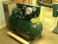
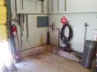
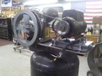
mounting bolts off flush with the floor .

cleaned out the old mix-n-match of outlet line to dryer / filter ( nothing in its case :scared: ) and this let me turn the tank 90* and set it back in a bit more to open up a LOT more floor space .

the new top plate on this one also helped a lot . spacing is a lot better now.

and I let the blood out of the old pump . . . she was gray and black with clean oil on top :headscrat . . . but turn by hand bench test pin pointed the problem why it was so hot / wouldn't get over 120psi the blow by in to the crank case was so bad it was almost ready to pop the filter out of the vent / fill port . :scared: ........ so glad I didn't waste money on parts for that pump . :bounce:
 

Attachments

  • 0806161416a.jpg
    0806161416a.jpg
    130.7 KB · Views: 37
  • 0806161709a.jpg
    0806161709a.jpg
    128.8 KB · Views: 42
  • 0806161901a.jpg
    0806161901a.jpg
    130.2 KB · Views: 43
OP
S

sweetk30

Well-known member
Joined
Jan 2, 2011
Messages
2,306
Location
finger lakes area upstate ,ny
so my major question of the day . . .

how to mount the motors to the plates and make them easy to adjust for belt tension . ? ?

I was looking at these on ebay http://www.ebay.com/itm/adjustable-...629461?hash=item1a168f2495:g:XrMAAOSwwo1XetQ1

for 30 bucks each shipped I think its almost a no brainer unless you guys got other ideas .

my 2 motors share the same bolt pattern . but the frame # on the tags is different ? ??

front / shaft to back is 4.5"-5.5" slotted . then side to side is fixed 7.5" wide.

so would the frame I linked work ? I didn't see specs in the linked one or others .

I figure this keeps it simple stupid and easy mount to top plate with rubber under the 4 bolts to plate . then adjust the motor with 1 bolt in/out for belt.
 

Attachments

  • s-l1600.jpg
    s-l1600.jpg
    41.9 KB · Views: 24

redmondjp

Well-known member
Joined
Nov 25, 2014
Messages
2,318
Location
Redmond, WA
I think your idea above about using the pre-fabricated motor mount is most excellent. I have a couple of compressors that were built with that tensioner setup built into the base plate, albeit without any rubber isolation.

For that price, heck yes, it's a no-brainer. Thanks for posting that, as I was unaware that you could even buy such a part.
 

PSYKO_Inc

Well-known member
Joined
Oct 23, 2010
Messages
565
Location
Fairfield, CA
I've had a couple compressors with the sliding motor plates like those, they work well. Bummer about the blow by, sounds like new rings are in order. Are you planning on rebuilding it or just looking for another pump?
 
OP
S

sweetk30

Well-known member
Joined
Jan 2, 2011
Messages
2,306
Location
finger lakes area upstate ,ny
I've had a couple compressors with the sliding motor plates like those, they work well. Bummer about the blow by, sounds like new rings are in order. Are you planning on rebuilding it or just looking for another pump?

that was the old original 2 stage pump from the 80gal .

the new to me pump to replace it is the IR 2545 unit that I got for the price of a rebuild kit for the crappy pump .
 

md21722

Well-known member
Joined
Nov 30, 2015
Messages
1,840
Location
Mt Juliet, TN
You are correct. I would want a hose good to at least 350 deg F. Look up Eaton aeroquip hose. I forgot where I ordered mine from but I am using that hose for a compressor discharge - it's one of the applications listed in the specs for this hose. It's extruded teflon with stainless steel braid. They have hose good to 450 and 500 deg F and well beyond any pressure they would ever see.

I remember seeing places where you could have your hose made to order with crimped on fittings. There also compression type, reusable fittings, you can install yourself, swivel and diy crimp fittings.

ETA: http://www.hosewarehouse.com/aeroquip
http://hosewarehouse.com/Hydraulic/...C807-16-Aeroquip-PTFE-Hose?mfp=68-application[Hot%20Air]

How long of a run do you think you'll need to make? You don't want too much volume of hose/tube between the compressor discharge and check valve or else pump performance will suffer.

I'm not 100% with this information. I use stainless steel braided available from my local compressor shop or Grainger/Zoro. These types of hoses come with a NPT union for easy assembly and disassembly. Copper discharge hose with compression fittings is another way to go. I fail to see how volume of hose/tube between compressor and check valve would cause performance to suffer. By the time folks add after coolers and other plumbing, the length goes up. In industry compressors are not even mounted to a receiver. Compressors may be mounted on a large frame with a large receiver a bit away.
 

md21722

Well-known member
Joined
Nov 30, 2015
Messages
1,840
Location
Mt Juliet, TN
my 2 motors share the same bolt pattern . but the frame # on the tags is different ? ??

front / shaft to back is 4.5"-5.5" slotted . then side to side is fixed 7.5" wide.

so would the frame I linked work ? I didn't see specs in the linked one or others .

I figure this keeps it simple stupid and easy mount to top plate with rubber under the 4 bolts to plate . then adjust the motor with 1 bolt in/out for belt.

Just because the motor frame is different doesn't mean the bolting pattern is completely different.

The "length" between mounting holes is usually the most critical,
184 and 213 are both 5-1/2" long
215 is 7" long

The "width" isn't as important because tank top plates are usually slotted to allow the motor to slide to set belt tension
184 is 7.5" wide
213 and 215 are 8.5" wide

5HP, 1725 RPM motors are available as 184, 213 frame
7.HP and 10HP, 1725 RPM motors are available as 215 frame
 
Last edited:
To avoid these ads, REGISTER NOW!

md21722

Well-known member
Joined
Nov 30, 2015
Messages
1,840
Location
Mt Juliet, TN
I'm not clear on your question. If you have a 184 frame motor then you'd want a 184 adjustable steel motor mounting base as linked on eBay. Just make sure your top plate is large enough for it. These typically work on top plates that are 13" W or larger.
 

md21722

Well-known member
Joined
Nov 30, 2015
Messages
1,840
Location
Mt Juliet, TN
There is one other thing I wanted to say. You typically do NOT want to take air from the TOP of the tank. Take it from a lower point. Heat rises. Put the compressor discharge in the top and take out from the lower side point to your air distribution system.
 
OP
S

sweetk30

Well-known member
Joined
Jan 2, 2011
Messages
2,306
Location
finger lakes area upstate ,ny
I'm not clear on your question. If you have a 184 frame motor then you'd want a 184 adjustable steel motor mounting base as linked on eBay. Just make sure your top plate is large enough for it. These typically work on top plates that are 13" W or larger.

ya just wanted to make sure the 184 pattern size was good for my motors since the 1 shows the other style not even close to a 184 even tho it measures out the same pattern.
 
OP
S

sweetk30

Well-known member
Joined
Jan 2, 2011
Messages
2,306
Location
finger lakes area upstate ,ny
There is one other thing I wanted to say. You typically do NOT want to take air from the TOP of the tank. Take it from a lower point. Heat rises. Put the compressor discharge in the top and take out from the lower side point to your air distribution system.

kind of limited hear I guess . the top port is just a 1/2" welded in bung . and my newer BIG pump is 3/4" outlet . and if I ever went bigger motor I would be over the 20cfm spec of the 1/2" check valve .

for now I guess I could go back to top load side exit for the air tank . . . . but when I plumb it to the shop lines and I ever change it I will be redoing it all again .
 

md21722

Well-known member
Joined
Nov 30, 2015
Messages
1,840
Location
Mt Juliet, TN
I would say tank discharge in the top and change it later if you go to a bigger motor. Who knows by then you may get a larger tank or a different compressor entirely.
 
OP
S

sweetk30

Well-known member
Joined
Jan 2, 2011
Messages
2,306
Location
finger lakes area upstate ,ny
also I could just get a inline check valve style and reduce it to 1/2" to drop in the tank top for now . then later on I would be ready for upgrade as I could reuse the inline check valve and remove the reducer . ? ?

p.s. thanks for working with me.
 

md21722

Well-known member
Joined
Nov 30, 2015
Messages
1,840
Location
Mt Juliet, TN
The style you bought and attached a picture in post #46 is what I would use. I would do it the cheapest way possible, that may mean buying another 1/2" check valve. The reason I suggest this is that the top of my 60 gallon horizontal tank get to 145F by the discharge inlet and the other side of the tank where it goes into my air system is around 100-110F. That's a 30-40F difference. The cooler the air, the more chance you have of getting water out of it. Hot wet air will pass straight through the filter and regulators and condense in your tools. This is why you should never put a filter regulator right on your tank, unless maybe you have an after cooler that cools to ambient or very close to it. You could do it your initial way and change it later if needed.
 

vandalthree

Member
Joined
Jul 29, 2016
Messages
23
An after cooler is a great way to go. You can make one from just about any automotive AC condenser. My compressor is set up with one from an old cadillac. Air goes in hot, comes out cool. No water issues at all even on the most humid of days.
 
OP
S

sweetk30

Well-known member
Joined
Jan 2, 2011
Messages
2,306
Location
finger lakes area upstate ,ny
I don't have a problem buying the inline style check valve . and it would be more universal for me later on . will keep the reg style for later use .

I see using a a/c condenser on some smaller units . but with the cfm this will pump I am not sure it would flow the cfm I need or could produce.

I don't think on average I will be pulling this much air . but if I do later on this is my system to build that will be able to handle it already .
 

md21722

Well-known member
Joined
Nov 30, 2015
Messages
1,840
Location
Mt Juliet, TN
The aftercooler is sized to pump output not air demand. Aftercoolers are plumbed between pump and tank. I would get the highest flowing 1/2" check valve and drop it in the tank and work upwards towards the pump and be done with it. Like I said Champion among others uses 3/4" NPT from 2 to 7.5 and maybe 10HP. At some point the line size is generic to standardize parts. As an example you could plumb in some 3/4" NPT pipe fittings off the pump and go into a 3/4" flex hose to a reducer and pipe ****** to the check valve. Ever see old Quincys QR that were black iron to the tank? It isn't that big of a deal.
 
Last edited:
OP
S

sweetk30

Well-known member
Joined
Jan 2, 2011
Messages
2,306
Location
finger lakes area upstate ,ny
o.k. I get your points . ( not sounding mean )

and average car a/c condensers up in front of a radiator are around 3/8" line size . so to me stuffing the 3/4" outlet to 3/8" and back up is a massive choke point for this size compressor .

now maybe the other smaller pump/cfm units will be fine this way . ? ? ?

I know the evaporator ( in the dash ) has bigger tubes on it . but not sure what psi it could handle on a regular use for the high side of bigger 2 stage pumps.
 
Last edited:

md21722

Well-known member
Joined
Nov 30, 2015
Messages
1,840
Location
Mt Juliet, TN
Modern air compressor after coolers are usually around 3/4" - 1" up to 75 CFM that are designed for this purpose. Again, what's the points of having 1" NPT for 20 CFM up to 99 CFM? They are just standardizing that at that wide a spread. I just got a 1996 Champion VR5-12 yesterday. It is clearly a custom spec tank. Drilled for 5, 7.5, and 10HP motors. 3/4" inlet and outlet, and a bottom drain and a side siphon drain plus ports for the pressure switch and pressure gauge. Drilled for both the Champion R-15 and R-30 pumps and belt guards for each configuration. Point being, the manufacturers are standardizing parts to keep fewer parts in inventory...
 
Last edited:

Finky198

Well-known member
Joined
Feb 25, 2014
Messages
2,120
Location
North East
^^
^^

This is the same reason I never did the after cooler its not easy or Affordable to find a properly sized cooler for a bigger compressor, and I have yet to see any serious moisture issues...
 
OP
S

sweetk30

Well-known member
Joined
Jan 2, 2011
Messages
2,306
Location
finger lakes area upstate ,ny
ya if I wind up with a problem then I will prob just buy a real aftercooler .

no since on the BIG pump trying to home brew it and have a huge BOOM with chunks flying around .
 
OP
S

sweetk30

Well-known member
Joined
Jan 2, 2011
Messages
2,306
Location
finger lakes area upstate ,ny
stopped in to the local hose shop today .

said they can make me a steel braided hose that's used a lot for air hose off compressors to tank . said its fine in the 300 to 400 range temps.

I saw the hose and its a kind of whiteish/clear plastic inside with the s.s. braid on the outside .

does this sound correct ? ? ? I didn't happen to get brand/part# specs yet I forgot.
 

redmondjp

Well-known member
Joined
Nov 25, 2014
Messages
2,318
Location
Redmond, WA
stopped in to the local hose shop today .

said they can make me a steel braided hose that's used a lot for air hose off compressors to tank . said its fine in the 300 to 400 range temps.

I saw the hose and its a kind of whiteish/clear plastic inside with the s.s. braid on the outside .

does this sound correct ? ? ? I didn't happen to get brand/part# specs yet I forgot.

Sound good to me - they are the experts. A lot of people have used hydraulic hoses for the same purpose - yes, overkill on the pressure rating but temperature rating is OK as well.
 

md21722

Well-known member
Joined
Nov 30, 2015
Messages
1,840
Location
Mt Juliet, TN
stopped in to the local hose shop today .

said they can make me a steel braided hose that's used a lot for air hose off compressors to tank . said its fine in the 300 to 400 range temps.

I saw the hose and its a kind of whiteish/clear plastic inside with the s.s. braid on the outside .

does this sound correct ? ? ? I didn't happen to get brand/part# specs yet I forgot.

Sounds fine to me. What price are they asking? My local compressor shop sells 3/4" 24" long for $45. It seems Chinese made. Better quality made in U.S.A. from Zoro is around $70. 3/4" copper refrigerant line is another option if you feel like bending it. There is little risk in using black iron with a short piece of flex, the temps are high enough out of the pump rust is a non issue. I have seen black iron used 40-60 years old and looks new.
 
Last edited:
OP
S

sweetk30

Well-known member
Joined
Jan 2, 2011
Messages
2,306
Location
finger lakes area upstate ,ny
o. . . m . . . g . . . :shocking:

so last sunday night placed order with amazon 2 adjustable electric motor plate mounts . clicked the prime trial with 2 day free ship . . . . . .

showed more than 4 in-stock and sold by amazon . took them 3 business days to ship them out . and as said 2 to get to me . W.T.F :wtf:

so the box showed up today TRASHED 1lb extra tape ( thanks fedex ) so I take pics of the box before I open it . the bottom has some of the mounting studs blown out of it . :scared: and I open it to find no extra beefy anti blow threw packing . just 1 wrap of tiny bubbles wrap on 1 then other set on top and the shipping air filled bags and all of them popped ! ! !

the bottom one was set in the box with no chance ever of making it here with no damage as it was set in studs down = the bottom blow out .

well I get them both out and the threads on both units studs are boogered to the point they all need cleaned up BIG time but I said no when I found 1 of them that was on the bottom unit that went threw the box was bent more than 20* off its 90* from plate spec.

so I called them up and they said we can ship you a new set next day shipping for sat delivery no charge . . . . . we will see just how this plays out .

-----------------------------------------------------

but on a good note I did get the 1 small unit all done today with using 1 of the mounts for all my layout work as a template . so when the new show up in better condition I hope it should be bolt on / tighten belt / plug in / fire up .

ahhhhhhhhhhh I hate it when people don't do what they say they can do or will do .

and I did get a new power switch for the smaller unit with a unloader valve port to add in to the system since it didn't have one before on the old setup mix-n-match it was .

got her all rubber mounted also . rubber between old/new top plates . rubber between pump/motor & new top plate . will even be doing it between the floor to tank mount feet .
 
OP
S

sweetk30

Well-known member
Joined
Jan 2, 2011
Messages
2,306
Location
finger lakes area upstate ,ny
few box pics of packaging short falls .

and 2 of the small unit ready for a TEST FIRE :3gears:

sat we be digging out the BIG boy and get him all done up .
 

Attachments

  • 0812161213a.jpg
    0812161213a.jpg
    127.6 KB · Views: 22
  • 0812161213c.jpg
    0812161213c.jpg
    127.7 KB · Views: 19
  • 0812161214a.jpg
    0812161214a.jpg
    129.3 KB · Views: 20
  • 0812161215a.jpg
    0812161215a.jpg
    111.3 KB · Views: 24
  • 0812161216a.jpg
    0812161216a.jpg
    149.1 KB · Views: 26
  • 0812162120a.jpg
    0812162120a.jpg
    133.5 KB · Views: 38
  • 0812162120b.jpg
    0812162120b.jpg
    134.1 KB · Views: 41
To avoid these ads, REGISTER NOW!
Top Bottom