To avoid these ads, REGISTER NOW!

Atlas 1020 drill press refresh, keep or replace this old electra motor

shannonw

Well-known member
Joined
Jun 18, 2010
Messages
660
Location
Florida
Been awhile since been here, been busy with other **** and got an urge to clean something up as my China drill press *****.

Whatya think? it’s more of a looks question as opposed to functionality.

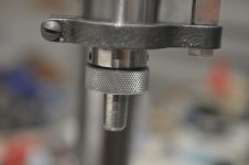
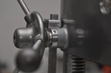
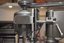
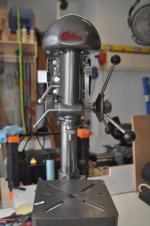
It runs! This was the press when i picked it up, holy smokes 30 years florida humidity in a shed i think. it’s currently stripped down most of the paint and rust removed. This is an ‘electra' made in cali 1/3 horse motor....i got it torn down too. Kind of a unique looking motor but a weightly sob for 1/3 horse and large...this thing is probably at least 3 times the size of my 1/3 horse cheapie Chinese junk press motor.

On one hand it looks kinda cool, on the other it’s going to add some significant weight and depth to the whole thing and is pretty big. I’d have to splice the wires where they go to the box as they’re in sad shape there, clean everything, it has a capacitor so i’d replace that, then there’s what i guess is a centrifugal switch i still need to look over good.
 

Attachments

  • 01111_fcFjmmSI9rS_1200x900.jpg
    01111_fcFjmmSI9rS_1200x900.jpg
    146.3 KB · Views: 154
  • 00808_eFaEPA1jxqR_1200x900.jpg
    00808_eFaEPA1jxqR_1200x900.jpg
    145.5 KB · Views: 142
To avoid these ads, REGISTER NOW!
OP
S

shannonw

Well-known member
Joined
Jun 18, 2010
Messages
660
Location
Florida
few in progress pics...waiting to get some time to degrease, remove rest of paint and rust then paint
 

Attachments

  • IMG_1091.jpg
    IMG_1091.jpg
    138.4 KB · Views: 105
  • IMG_1092.jpg
    IMG_1092.jpg
    136.8 KB · Views: 98

schor

Well-known member
Joined
Apr 16, 2013
Messages
531
Location
Ajax, Ontario
Are there bearings in the motor or just bushings? Replace the bearings and check the wiring, some paint and you should be good with that motor if it runs now.

Here's a pic of my atlas 42b. I have some vids on it on my youtube channel.

diAb87aB5GBR3PCCLsaQ7Q4Mt2bfZkMYiW2AlyvXPGe_M46IQtJ_uQfWu_IVI2SleLj-hxfvoFrsQLBANxHt5ajBe42l7rnVH6eq9y_zwFX0GRAS9s-lbFtN_i7hEjsPzoLXnl2GtK7Kx--b4lRrTm0ZZmNVUitbEGWZTu16BZ6spdT_zw71vLkMW3o9v6yhTT-SYKvwyNjE5b3jdS_9Q4lnh_GpwuP0FHUQ8MHgKbCbqLLUOGP7ZCtC-Qk7Rv8eiarueRZdO5vRGKEUducYl0TozDhBcbpFLsKPf1uyiF_9PPJ4HYSlE7acz7rMfgcm7HNCPIFYCmOJSIuArf92PEWZzXhrGtBWkQArQ49r3kkWMsuTIiRjsHrgq0f0dn6y_ehmOWhNA3YntW86uOoTU7JlF3jRYZxJ2PtjvKuBKtMK7wexJmYk_6sVg8CjSSHskl3cJEbT_CEykxpQHorgQQ6ycY1FXaO1KpvNA3APm-M7RsbMrJ_nwJgufgPmAunECbmijcEaiZgYOQG1g_4zXGso8m1WYuHl4YIVy7fIYNbJARaReJ40sG3JObDc3ftBk5bDGhIx1rZYaqyDBrdLr0msRpgPvDA=s875-no
 

Davefr

Well-known member
Joined
Jan 7, 2010
Messages
11,826
Location
OR
Keep the original motor. They're really easy to rebuild.

- Disassembly and clean
- Flush and relube or replace the bearings
- Ensure all wiring is in good shape.
- Polish the centrifical contacts
- Strip and paint the case
- Test the cap, if it tests good re-use it.
 
OP
S

shannonw

Well-known member
Joined
Jun 18, 2010
Messages
660
Location
Florida
Yes there’s bearings, 2 up front look sealed and seem smooth (whole motor rides off the front bearings) but probably worth replacing while it's apart since i have them out.

i’ll inspect the wiring,centrifical and capacitor tonight.

Steve yes i’ve seen your drill press test which got me looking for an older press...on a whim this popped up. Bit rougher than i was looking for and was looking for older with the older body style, but this was close by, 50 bucks (didn’t feel like haggling) and looks complete including chuck key. Only thing i note missing is the return spring and return spring cover...2” electrical box knockout cover fits for now and i’ve ordered a spring i hope fits...maybe just picked a spring of amazon that was close to the dimensions and for a 12-15” press...if you know one that does work it may come in handy, should arrive tomorrow.

Few chips on the top motor pulley step but instead of trying to hunt a pulley i think that’s minor enough jb weld and some filing ,sanding can handle.

What kind of paint are you using? Some grey like that is what i’m looking for.
 
OP
S

shannonw

Well-known member
Joined
Jun 18, 2010
Messages
660
Location
Florida
Got degreased and rest of paint removed this morning. Then I realized...

I take it I should punch these split cotters out? and lube and clean this area? Not familiar with them, they’re in there solid, not sure if they’re supposed to have some play or not? i’d think so as looks like they close and open around the column with the levers..they’re going no where as is.

There’s one in the main casting and another in the assembly that holds the table on, the one by the quill fell out (which is what made me realize these others are frozen in).

Should i only knock out the non lever side?
 

Attachments

  • IMG_1100.jpg
    IMG_1100.jpg
    142.2 KB · Views: 79
  • IMG_1099.jpg
    IMG_1099.jpg
    144.9 KB · Views: 85
Last edited:

schor

Well-known member
Joined
Apr 16, 2013
Messages
531
Location
Ajax, Ontario
Yes there’s bearings, 2 up front look sealed and seem smooth (whole motor rides off the front bearings) but probably worth replacing while it's apart since i have them out.

i’ll inspect the wiring,centrifical and capacitor tonight.

Steve yes i’ve seen your drill press test which got me looking for an older press...on a whim this popped up. Bit rougher than i was looking for and was looking for older with the older body style, but this was close by, 50 bucks (didn’t feel like haggling) and looks complete including chuck key. Only thing i note missing is the return spring and return spring cover...2” electrical box knockout cover fits for now and i’ve ordered a spring i hope fits...maybe just picked a spring of amazon that was close to the dimensions and for a 12-15” press...if you know one that does work it may come in handy, should arrive tomorrow.

Few chips on the top motor pulley step but instead of trying to hunt a pulley i think that’s minor enough jb weld and some filing ,sanding can handle.

What kind of paint are you using? Some grey like that is what i’m looking for.

The paint is duplicolor wheel paint graphite color. Holds up great, I tested it on my lathe cross slide cover and put cutting oil, coolant, etc and nothing eats it.

http://duplicolor.com/product/wheel-coating
 

schor

Well-known member
Joined
Apr 16, 2013
Messages
531
Location
Ajax, Ontario
Got degreased and rest of paint removed this morning. Then I realized...

I take it I should punch these split cotters out? and lube and clean this area? Not familiar with them, they’re in there solid, not sure if they’re supposed to have some play or not? i’d think so as looks like they close and open around the column with the levers..they’re going no where as is.

There’s one in the main casting and another in the assembly that holds the table on, the one by the quill fell out (which is what made me realize these others are frozen in).

Should i only knock out the non lever side?

Do you have the parts diagram? Check vintagemachinery.org for it. Yes they should come out easily.
 

FrankLee

Well-known member
Joined
Sep 13, 2010
Messages
3,590
Location
seMI, 48317
Got degreased and rest of paint removed this morning. Then I realized...

I take it I should punch these split cotters out? and lube and clean this area? Not familiar with them, they’re in there solid, not sure if they’re supposed to have some play or not? i’d think so as looks like they close and open around the column with the levers..they’re going no where as is.

There’s one in the main casting and another in the assembly that holds the table on, the one by the quill fell out (which is what made me realize these others are frozen in).

Should i only knock out the non lever side?

Do you have the parts diagram? Check vintagemachinery.org for it. Yes they should come out easily.

Yes, take them out and clean them. They should free-float.

More info on those locks here:
http://www.garagejournal.com/forum/showthread.php?p=5443008#post5443008
 
OP
S

shannonw

Well-known member
Joined
Jun 18, 2010
Messages
660
Location
Florida
Thanks. That’s what i thought. These soaked for couple days in pb blaster, using a punch they just split apart. I shouldn’t have hit them as hard as i did (i put a washer down under the punch to spread the load) but i doubt they were coming out anyways. I think the salt air welded them to the cast iron, they’re some kind of cast pot metal, that stuff welds itself in florida.

No saving these, I’ll have to think, been googling but doesn’t seem there any sort of generic split collars you can buy that i can find?. Machining one may be problematic with no lathe, if i could find some brass stock drilled through already i could probably cobble the notch somehow.
 

FrankLee

Well-known member
Joined
Sep 13, 2010
Messages
3,590
Location
seMI, 48317
Thanks. That’s what i thought. These soaked for couple days in pb blaster, using a punch they just split apart. I shouldn’t have hit them as hard as i did (i put a washer down under the punch to spread the load) but i doubt they were coming out anyways. I think the salt air welded them to the cast iron, they’re some kind of cast pot metal, that stuff welds itself in florida.

No saving these, I’ll have to think, been googling but doesn’t seem there any sort of generic split collars you can buy that i can find?. Machining one may be problematic with no lathe, if i could find some brass stock drilled through already i could probably cobble the notch somehow.

I'm fairly certain that the lock cylinder diameter is common among several brands. Length could be the limiting factor. Here's a Craftsman head frame lock set on ebay right now for a reasonable BIN price (not mine):
http://www.ebay.com/itm/Craftsman-1...006519?hash=item33bcfca6f7:g:EuQAAOSwZVlXlWhj

What dimensions do you need?
 
Last edited:
OP
S

shannonw

Well-known member
Joined
Jun 18, 2010
Messages
660
Location
Florida
That’s an option too, forgot atlas made the craftsmen models not 100% sure which are similar. I’ll have to measure tonight, i’ll need 2 sets as these things are welded in and i’ll have to drill them out
 
OP
S

shannonw

Well-known member
Joined
Jun 18, 2010
Messages
660
Location
Florida
All 4 are 1 inch long, 1 1/4 thick...so that gives me something to email the sellers about.

just got done drilling them then knocking them out they were in there good i suppose they had expanded at some point maybe. In hindsight a large punch on the outside may have worked i dunno, the nut side just cracked, and i thought I was going to break the casting. But spilled milk now they’re out. Time to find replacements.
 

FrankLee

Well-known member
Joined
Sep 13, 2010
Messages
3,590
Location
seMI, 48317
The set in that auction is a head frame lock for a craftsman 150. Those cylinders are about 1-9/16" long. That will work for you but will stick out each side about 1/2".
I'll check my spare parts stash.
 
OP
S

shannonw

Well-known member
Joined
Jun 18, 2010
Messages
660
Location
Florida
Hi Frank,

indeed the sellers for the 100 series i’m seeing are all saying 1” X 1 1/2. May have to do that. Looking at vintagemachinery i’m seeing Atlas 62 , 63 , 64 , 72 , 73, 74 may have the same part number as the 1020 (still looking but they’re matching so far) and those correspond to craftsmen 101 possibly (not sure other craftsmen numbers yet) and a 101 handle lock cylinders on ebay looks noticeably shorter (but more expensive too). I’ll probably use whatever cheapest I can find that will work for now.

CAP was not looking good, ordered a new cap and 2 bearings for the motor, cut the frayed wires back so ready to tie into those. Was hoping to wrap this up this weekend but these column locks are going to delay that. The front one by the spindle i see now goes in and out easy, one of these column ones i did knock out OK...won’t go in at all i’d have to sand it. Who knows with the column rust, getting the head and table off could have been anything...no wonder the head and column were so !@#!@! hard to get off, pb blaster, heat, hours of banging, cleaning the column around them...finally 20 ton bottle jack took them off in 2 minutes. With those out everything slides on the column easily i see now lol.

Steve yeah I did my air compressor pump and baldor motor with duplicolor engine paint I had laying around, seems to do ok with incidental oil.

http://www.garagejournal.com/forum/showthread.php?t=219581

Thanks for the info, probably go that route again with wheel or engine paint.
 
OP
S

shannonw

Well-known member
Joined
Jun 18, 2010
Messages
660
Location
Florida
50-44 and *edit* 50-45 are the ones I need, but now that you mention it ....

the ones you mention by the spindle.....i note 1 just slid right out, the other nut/lock side is in there.

I wonder if I should try to get that loose. This time i think i’d use a bit more heat and punch from the *outside* as it was the inside with the notch that was pretty fragile. I wasn’t sure if they seated somehow so was trying to go from in to out.

I dunnu...think i need to get 1 of the pair loose? I suppose so as they both sort of pull together.
 
Last edited:
OP
S

shannonw

Well-known member
Joined
Jun 18, 2010
Messages
660
Location
Florida
Moved along to the chuck it was’nt really too bad rust wise, just surface rust. After soaking a few days in penetrant it would move really easy then bind up or only move easy one way after binding and wouldn’t close all the way. Once it bound only the key could turn it. Disassembled and see metal shavings here and there sticking to stuff,

on the teeth, this is what i see, do these look like the top row of teeth are gone? or is that how they cut them. i definently see a chip on the bottom row of one but it’s not a full thread just a sliver (3rd on the very right), top thread of 2 & 3 i can’t tell if it’s missing or just how these are cut?
 

Attachments

  • DSC_0015 7.jpg
    DSC_0015 7.jpg
    131.3 KB · Views: 59
To avoid these ads, REGISTER NOW!

FrankLee

Well-known member
Joined
Sep 13, 2010
Messages
3,590
Location
seMI, 48317
Moved along to the chuck it was’nt really too bad rust wise, just surface rust. After soaking a few days in penetrant it would move really easy then bind up or only move easy one way after binding and wouldn’t close all the way. Once it bound only the key could turn it. Disassembled and see metal shavings here and there sticking to stuff,

on the teeth, this is what i see, do these look like the top row of teeth are gone? or is that how they cut them. i definently see a chip on the bottom row of one but it’s not a full thread just a sliver (3rd on the very right), top thread of 2 & 3 i can’t tell if it’s missing or just how these are cut?

That's how they're cut. Did you mark them? They have to go back in the same relative position to each other as when they were removed. The body of the chuck should be marked 1,2,3 or I,II,III.
 
OP
S

shannonw

Well-known member
Joined
Jun 18, 2010
Messages
660
Location
Florida
I did mark them and the body so i’d know, i knew they go in a certain position.

Ok well worth a clean up and see
 
OP
S

shannonw

Well-known member
Joined
Jun 18, 2010
Messages
660
Location
Florida
Success, very smooth now =) a step ahead after the collar locks step back ...which i probably could have avoided if i’d have read franks faq beforehand, going to more time there before going into an unknown when i get stuck on something.

Yeah the cuts are obvious now (though not by reading jacobs docs which i did before marking them) 1,2,3 you can tell by the steps. 1 small step, 2 full step, 3 no step in the last thread. The jacob docs make it look like you’re looking at the edge of the jaw.

Pressing apart and together, i used EMT conduit couples of couple sizes with my bench vice like i read on someones thread.

I did not think it would reassemble, couldn’t get the jaws back in, then looking where the jaws slide in was a film of build up grease or who knows just a light film dried up which was enough to keep me from reassembling, that’s why the thing was so darn hard to move and get the jaws out. Grabbed what was next to me a sharpie and wrapped sand paper around it (couple grades 320 then a lighter)...worked good. If i had had a dowel i think i’d of rigged something up with the drill.

After that though slid right together! That chip at the end of one of the jaws partial last thread i think i did knocking that jaw out, in hindsight my punch must have got it right on the edge, gotta make sure when knocking these out you’re center or away from the end with the thread. But it doesn’t matter i can’t tell it affects thing.
 

Attachments

  • DSC_0003 10.jpg
    DSC_0003 10.jpg
    123 KB · Views: 34
Last edited:

Roberts210

Well-known member
Joined
Dec 21, 2015
Messages
3,177
Location
Missouri
Shannon, one thing about the old motors that are heavy and large in diameter is they are very torquey. Your "1/3" h.p. motor will probably out drill any 1/2 horse motor made today
 
OP
S

shannonw

Well-known member
Joined
Jun 18, 2010
Messages
660
Location
Florida
Roberts, thanks for the info, a good point! I got the paint off the space egg looking motor yesterday, body is all aluminum,It’s a 110/220 depending on how it’s wired. kind of an interesting looking motor, it for sure has that 50’s style to it, I can’t help thinking that may need some unique color

i found reference to it on vintagemachinery

http://vintagemachinery.org/photoindex/detail.aspx?id=16987

and a patent http://www.google.com.uy/patents/USD154811

for an ornamental style of a motor.

Received a capacitor today, bearings should be here tomorrow, this weekend i’ll solder and shrink the new leads, clean up the centrifugal and hopefully have that back together to test.
 
OP
S

shannonw

Well-known member
Joined
Jun 18, 2010
Messages
660
Location
Florida
They apparently made fractional hp motors (as i’m sure a lot did), the one on vintagemachinery is a 1/2 horse, this one is a 1/3 from the tag.
 
OP
S

shannonw

Well-known member
Joined
Jun 18, 2010
Messages
660
Location
Florida
Anyone ever seen a start winding switch (my guess... as it was connected to the capacitor) like this? It doesn’t mount anywhere where it would be spinning you can tell by the before picture. It was tucked behind a shield with the cap in the back bell housing. This motor is odd as there is no bearing in back, the rotor and shaft all ride off 2 bearings in the front bell housing it’s a couple inch tube extrusion in the front main body for the bearings and they’re separated on the shaft by lockrings, everything from there on back cantilevers.

I’m curious how it works, i can tell it sort of springs and closes some contacts, i guess it gets energized to a certain level somehow?
 

Attachments

  • IMG_1093-2.jpg
    IMG_1093-2.jpg
    137.6 KB · Views: 42
OP
S

shannonw

Well-known member
Joined
Jun 18, 2010
Messages
660
Location
Florida
Just a progress update...pics in various stages of cleaning. Started priming some pieces. For most stuff i did mechanical flap disk but mostly a fiber drill cup disks like these

https://www.amazon.com/dp/B00004YYD1/?tag=atomicindus08-20

they are great followed by evaporust , only have a gallon so for the base i’m trying vinegar it’s soaking now then rest mechanical again tomorrow. Table has mostly been stripped but still some cleaning there tomorrow.

Not even gonna attempt to remove the column from the base. I’ll polish around it as is. Tempting but my gut says i’ll break more of those cotter locks. BUT who knows =) maybe i’ll get a wild hair.

The motor is a beast compared to my cheapie, cleaned, replaced bearings, tied in new wires to the bad cloth areas. It’s 6 amps according to the label. Started fine and it sounds like it doesn’t play around, though shortly blew the new cap the start relay is bad for sure after i figured out how to test it. Still checking on that, i’ve been informed by a shop in email they no longer make those open frame relays but that i should look into a solid state switch. So i’m checking on that and confirming there info.

The chrome on the handles (4th pic) is shot. Not sure what i’m gonna do there, are these steel underneath? The threaded portion is shiny. I dunno i may just dip em or spray them in plastidip until i figure out what to do. Maybe i can remove the chrome and polish? Maybe some point i have some powder coating i need done soon i’ll take those with me.

Also is a pic of the fine piece of machinery this press will be replacing. Not sure how much extreme polishing i’ll be doing we’ll see i’m rushing some things to get this done as I have a need for a drill press table which is why I bought this.
 

Attachments

  • DSC_0009 6.JPG
    DSC_0009 6.JPG
    143 KB · Views: 53
  • DSC_0008 6.jpg
    DSC_0008 6.jpg
    48.2 KB · Views: 51
  • DSC_0007 7.jpg
    DSC_0007 7.jpg
    52.2 KB · Views: 50
  • DSC_0006 8.jpg
    DSC_0006 8.jpg
    47 KB · Views: 50
  • DSC_0005 9.jpg
    DSC_0005 9.jpg
    46.8 KB · Views: 51
OP
S

shannonw

Well-known member
Joined
Jun 18, 2010
Messages
660
Location
Florida
An update for the GJ folk

I stink at colors so used steves choice, silver with bellair green on the motor
was a close second, followed by a plain dark flat grey as 3rd choice.

First time using evaporust...man that stuff is works addictively well. Only had a gallon so vinegar + manual followed by a naval wipe down, then rinse and dry for the left over light stuff for the base and table.

Tomorrow now that all the rust is gone YAY to not be covered in rust (still a couple small pieces in the jar) i start polishing the handles and other stuff. I’m going to try to remove the bad chrome from the locking handles and see if they’ll take a polish.
 

Attachments

  • DSC_0013 8.jpg
    DSC_0013 8.jpg
    99.5 KB · Views: 63
  • DSC_0008 7.jpg
    DSC_0008 7.jpg
    55.7 KB · Views: 64
  • DSC_0015 8.jpg
    DSC_0015 8.jpg
    65 KB · Views: 67
  • DSC_0007 8.jpg
    DSC_0007 8.jpg
    85 KB · Views: 57
  • DSC_0009 7.jpg
    DSC_0009 7.jpg
    102.5 KB · Views: 69

Davefr

Well-known member
Joined
Jan 7, 2010
Messages
11,826
Location
OR
That's one of the coolest shaped motors and your two tone color scheme looks great. Glad you could save it.
 
OP
S

shannonw

Well-known member
Joined
Jun 18, 2010
Messages
660
Location
Florida
Sorry got a bit behind updating this thread....on a wife deadline =) i’m pushing getting this done when i’m supposed to be finishing kitchen cabinets ...playin hooky from that for 3 weeks is stretching it ...ladies, when a guy says the kitchen will be done, it will get done, no need to remind him every 6 months...

Lots of progress since last update. Thanks for all the encouragement! Huge thanks to franklee for helping me out in PM on a few things.

Some of these pics are from last week. But drill is running assembled tonight! I can’t stop turning it off and on lol

A few things since last update...

Got the solid state relay in the other day and that did the trick for the old motor frame relay that was shot...no capacitor boom and cloud of smoke now, got some bump runs in, then just finished today getting most things assembled.

Found a spring return cap on ebay very reasonable, and 2nd return spring size i ordered worked.

Lots of filing, sanding, polishing rusted handles and such. Some things like that drill stop and the motor mount rods, handles (also pitted chrome) etc very pitted after de-rusting so had to file, sand,sand, polish.

I still have to go back finish some cleaning on handles and a few other things, just got em presentable, and have a few fasteners i’m working on (like the nameplate,etc)

didn’t want to fuss with the switch plate trying to make it look original so just buffed it out, cleared, then made a trim ring from a stainless grommet i found in my fasteners box. Inside the toggle switch, the little plastic lever that fits inside the toggle was broke, went to get a switch they looked more zinc than the original which is aluminum..got the switches and replaced the plastic thingy and was able to keep the original.

a jbox from an aluminum project box, and some cable glands and paint

Lots of fussing with the motor pulley, had vibration and too noisy testing it. tore the motor apart again as I wasn’t 100% sure that I hadn’t pooched the bearings as the cantilever shaft and rotor is an odd setup. As i suspected the aluminum body of this old motor is a bit noisy, you can set a bearing on the tube the bearings and cantilever shaft rotor rides in, and just set the motor shaft on it lightly to spin it by hand and hear it amplify...but still pretty quiet just not as quiet as a steel case motor.

Then it turns out i had a set screw in wrong holding the rotor to the shaft (dumb mistake...there was a dimple on the shaft for it that i didn’t notice)..ended up stripping that and had to retap (should have taken that day off as i broke a tap drilling screws for the machine tag instead of wait for rivits as well).

Still sounded odd and wobble, figured out pulley key was worn, had a spare in the garage. Lots smoother now after going through that! there’s still some slight wobble but i think that’s the pulley, not too bad.

Still fine tuning a few things like wrong belt size i picked up, fasteners, final polishing of a few things, etc but i’ll post up some finished pics when i get done in the next week, then on to checking run out.
 

Attachments

  • DSC_0002 13.jpg
    DSC_0002 13.jpg
    52.3 KB · Views: 64
  • DSC_0026 6.jpg
    DSC_0026 6.jpg
    55.5 KB · Views: 69
  • DSC_0012 8.jpg
    DSC_0012 8.jpg
    123 KB · Views: 58
  • DSC_0010 8.jpg
    DSC_0010 8.jpg
    134.7 KB · Views: 61
  • DSC_0005 11.jpg
    DSC_0005 11.jpg
    123.7 KB · Views: 56
  • DSC_0034 5.jpg
    DSC_0034 5.jpg
    65 KB · Views: 60
  • DSC_0040 5.jpg
    DSC_0040 5.jpg
    40.3 KB · Views: 77

FrankLee

Well-known member
Joined
Sep 13, 2010
Messages
3,590
Location
seMI, 48317
Your restoration is one of the nicest I've seen! I really like the color you used and the color combination. And yeah, that motor is very unique and very cool.
 
OP
S

shannonw

Well-known member
Joined
Jun 18, 2010
Messages
660
Location
Florida
Thanks franklee

Steve should have licensed that color, every time i googled atlas drill press and looked at colors his would pop up, people really seem to like it

Got a quick stupid question for you guys, the jacobs chuck key...the rod that goes thru the key is stuck on this thing, before i attempt any more to free this up, from what i recall these *do* move right (the rod thru the key)? It’s been so long since i’ve used one of these i can’t remember (i’ve had a combo one with different sizes forever)
 
OP
S

shannonw

Well-known member
Joined
Jun 18, 2010
Messages
660
Location
Florida
thanks farmall,

now that i look at this key closer, i guess they weld them otherwise it would fall off. For some reason i was thinking of keys (maybe it’s the cheap ones) where that rod moves. No biggie i was going to remove the rod to straighten it, i’ll work with it as is.
 
To avoid these ads, REGISTER NOW!
Top Bottom