Outlawmws
Well-known member
 but because the jaws may be hardened, and not easily drilled. (Dr' Scott's are definitely hardened)
 but because the jaws may be hardened, and not easily drilled. (Dr' Scott's are definitely hardened)
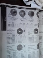
Having trouble finding the correct vise jaws for this utility Wilton. Wilton tech support can't find much but this catalog page. Mine is a 645 with 5" jaws that need replacing. One side is missing and one side is worn badly.
I have attached the flyer Wilton tech sent me for your review.
Vise jaw measures 5"L X 3/4"H X 1/4"W (thicker would be ok) with 1/4" -20 threads and holes spaced 3 1/4" apart.
Even the guy from wiltonparts.net didn't stock but could make me a set for about $70.00 he said the common Wilton holes are 2 3/8"
My question: I can use the ones I bought from Wilton, $40 all correct but the screw holes don't align. they are 2 3/8" center
If I did use them would you tap new holes in the vise itself or drill new holes in the jaws?
Thanks,
Will
Just bought a Reed 204 1/2 swivel vise that is in pretty nice shape. However, it is missing the handle bar for the locking mechanism. Since this is my first Reed vise, what would be the best way to go about trying to either find a used one (preferably) or create a new one.
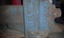
great reading . have you guys ever seen this vice company american chain co found in dads barn. cant seem to find any info.
great reading . have you guys ever seen this vice company american chain co found in dads barn. cant seem to find any info.
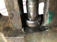
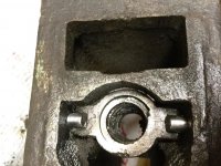
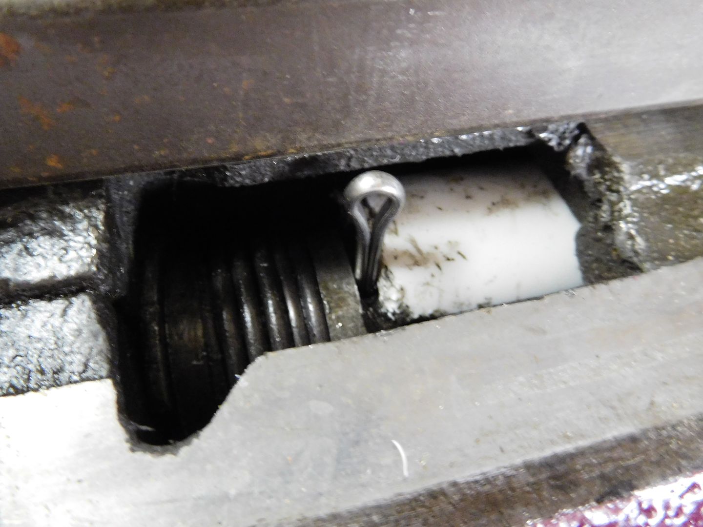
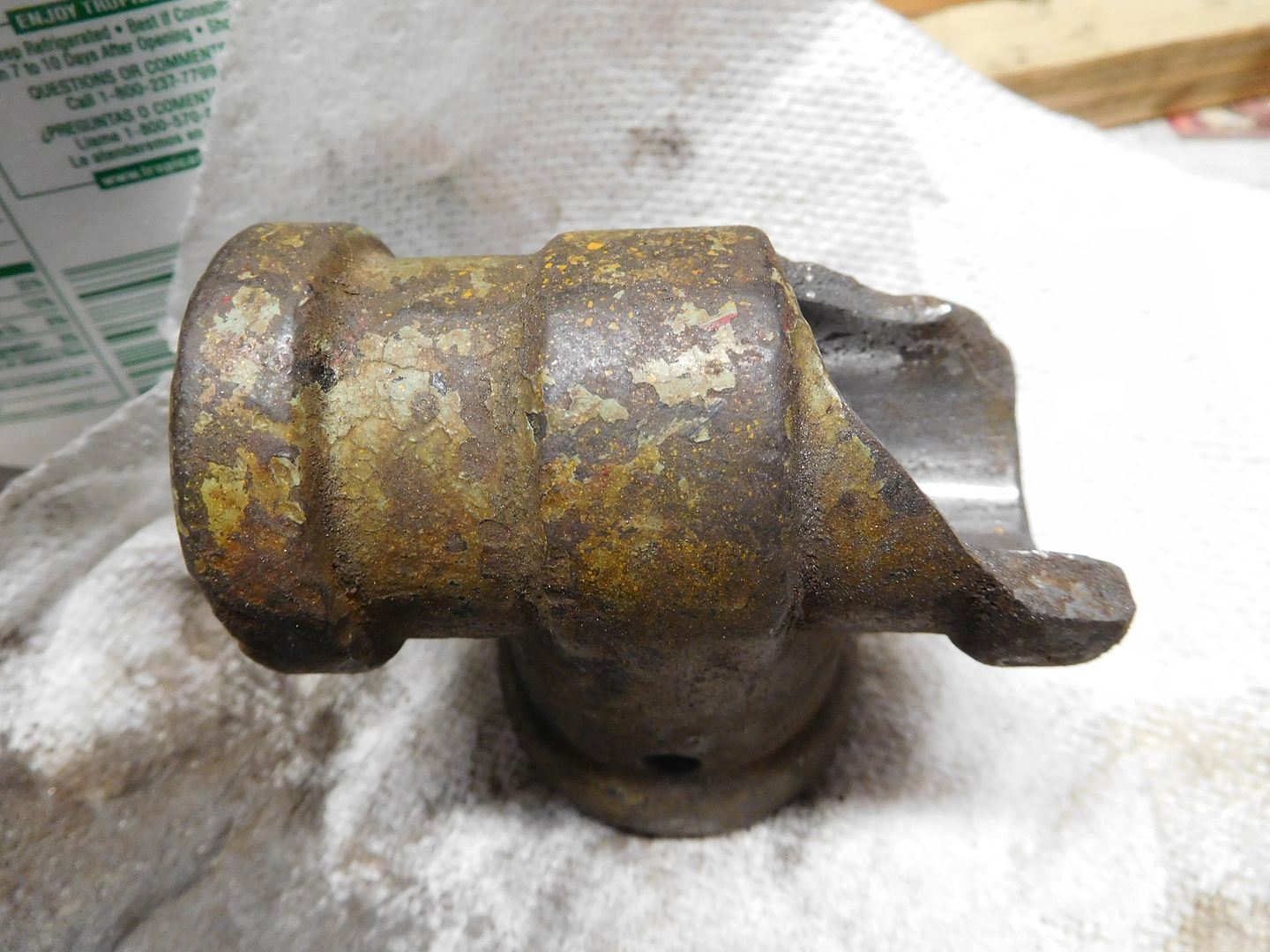
Started to tear down the Lewis 55 today and although seems pretty straight forward i have run into two issues. First, the main screw is held in place with a collar and screw similar to the setup on a Reed. However immediately behind and against said collar there seems to be 3 areas where they gouged out the surface of the screw in a wedge shape creating 3 raised areas that would prohibit the removal of the collar. (see pics below) Second the screw nut is being held in place by two pins and i cant get them to budge. Any ideas on how two address these two issues as i would really like to dissemble the unit completely for restoration.
Thanks Carla for the insight. So much for thinking id be done this evening with the restoration. One note, I will check this evening but I believe the nut pins have been driven from the inside and do not extend through the casting. If so, any ideas on how to remove said pins
Try King Architectural Metals, they have an online catalog
i don't own very many of these little clamp on vises and wondering if i can just unscrew them apart to clean and re grease or is there a clamp or a trick/tip i might need to know. this is a 2 inch wide jaw Wilton 1113 out of Chicago so if anybody has one or any history on them please post cause i thought Wilton only made baby bullets as their small vises.
It looks to me as tho the 1" dia. plain steel balls they list @ 85cts. would be an excellent component for replacement vise handles in the 9/16" and 5/8" diameters, as used on a very large variety of vises, in the 3-1/2", 4", and, in some makes, 4-1/2", jaw sizes.
My own preference would be to drill/tap the ball 1/2-20 x 3/4" dp., and thread the handle ends to suit. Assembly with Loctite would keep the ball ends from coming loose in service, but allow disassembly by gently warming the parts, should that ever be desired.
cheers
Carla
Try King Architectural Metals, they have an online catalog
Anybody have a source for steel balls that can be machined or welded to make replacement handles? Found this place http://bearingballstore.com/ , price of the soft steel balls seems a little steep.

Not sure if anyone has tried this or not: Needed a super small brush to paint lettering on vise. Took a q tip, removed the cotton and ground it to a point on the bench grinder. Worked awesome, pinpoint accuracy. The cardboard handle was absorbent and soft enough to hold and spread paint.
Mark
Sent from my iPhone using Tapatalk
Not sure if anyone has tried this or not: Needed a super small brush to paint lettering on vise. Took a q tip, removed the cotton and ground it to a point on the bench grinder. Worked awesome, pinpoint accuracy. The cardboard handle was absorbent and soft enough to hold and spread paint.
Mark


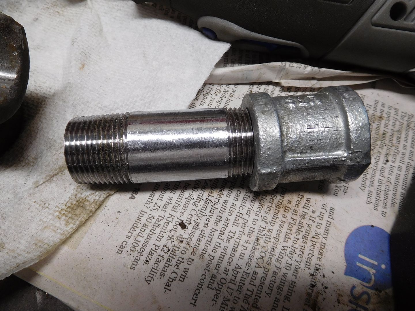
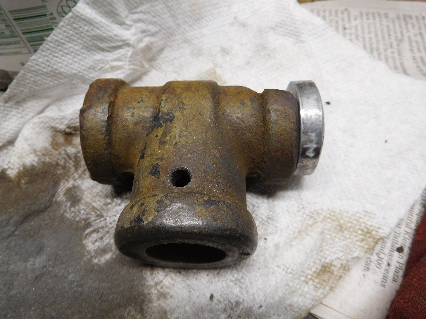
Jim, I wonder if you could mod a pipe tee to replace the whole broken part?I recently acquired a Rock Island woodworking vise with a busted nose.
Found some pipe fittings at HD. I filed the outside of the pipe and ground the inside of the broken Tee with my Dremel.
And then, bada-bing, bada-boom...
At this point, it is just a tight interference fit. I plan to insert a few random pins to keep it from moving.