To avoid these ads, REGISTER NOW!

Battery Charger Repair

Farmall 1066

Well-known member
Joined
Jul 21, 2012
Messages
1,805
Location
Suburban Rockford, NE
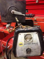
In my previous post about it, I found the selenium rectifier on my old Napa battery charger has shorted.
Been mulling over repair options, and got to wondering...could I substitute the bridge rectifier assembly out of a Delco truck alternator?
Just been kicking this around, and really can't see why it wouldn't work?
 
To avoid these ads, REGISTER NOW!

6PTsocket

Well-known member
Joined
Mar 12, 2014
Messages
4,593
They had big sink fins but handled very little current. Do you even know if it is a bridge, which is actually four rectifiers in a single package or as four separate diodes. If the transformer has a center tap there may only be two diodes. The Delco diodes should be plenty big but you have to know a little about DCpower supplies and know how to use a multimeter to check diode polarity. Also, if the diodes are pressed into the alternator for a hear sink, you will need to find some way to heat sink them. Bridge rectifiers are really cheap and even high current ones. Theg2 come in flat packs that are held to a heat sink with a single bolt. Places like DigiKey and Mouser have tons of them. If you have a schematic and any specs, like how many amps the charger is rated at, post them and I will help you find a modern replacement. Car companies sell inexpensive, off the shelf electroninc parts as expensive car parts. I just dealt with a $101 Subaru circuit breaker that was just a $15 Panasonic circuit breaker. OEM vs aftermarket might matter with mechanical parts but basic electronic parts from a reliable distributor are the same thing at a fraction of tbe price. I helped somebody replace a bridge rectifier on some piece of lawn equipment. It was around 5 bucks vs around 50 or 60 as an equipmenr replacement part. It was identical.

Sent from my SM-G900V using Tapatalk
 
OP
F

Farmall 1066

Well-known member
Joined
Jul 21, 2012
Messages
1,805
Location
Suburban Rockford, NE
Thanks!
This had 4 black plates, with a common bolt and insulators stacking it all together. Plates were brass on one side and natural metal finish on the other.
With this stack disassembled, and testing these plates individually, as diodes, one had substantially different readings than the others, and that one fell apart while checking.
I don't have a schematic but can send you some pics, if it would help.
 

Attachments

  • IMG_1256.jpg
    IMG_1256.jpg
    142.4 KB · Views: 104

Infinia

Banned
Joined
Oct 2, 2016
Messages
845
Location
SoCal
Hi
You can buy bridge rectifiers really cheaply (2-5 bucks) look for 25 Amp 200-400V they come in 4 terminal modules.
note > most chargers use only 2 rectifiers so you can configure a single 4 diode bridge to do the job using 3 terminals, not all 4. Heat sinking can usually be accomplished by bolting it to a large metal surface, it's electrically insulated. ( id use the chassis top or possibly the bottom for this )

please Google this stuff 'bridge rectifier 25Amp 400V' there are many flavors, even 50Amp up to 1000V you can use most any of them. There are many repair videos on Utoob id suggest looking there.
 
Last edited:

6PTsocket

Well-known member
Joined
Mar 12, 2014
Messages
4,593
Hi
You can buy bridge rectifiers really cheaply (2-5 bucks) look for 25 Amp 200-400V they come in 4 terminal modules.
note > most chargers use only 2 rectifiers so you can configure a single 4 diode bridge to do the job using 3 terminals, not all 4. Heat sinking can usually be accomplished by bolting it to a large metal surface, it's electrically insulated. ( id use the chassis top or possibly the bottom for this )

please Google this stuff 'bridge rectifier 25Amp 400V' there are many flavors, even 50Amp up to 1000V you can use most any of them. There are many repair videos on Utoob id suggest looking there.
Why is everybody trying to use a bridge for two diodes? If you need 2 diodes, buy 2 diodes. They are still very cheap

Sent from my SM-G900V using Tapatalk
 

6PTsocket

Well-known member
Joined
Mar 12, 2014
Messages
4,593
Hi
You can buy bridge rectifiers really cheaply (2-5 bucks) look for 25 Amp 200-400V they come in 4 terminal modules.
note > most chargers use only 2 rectifiers so you can configure a single 4 diode bridge to do the job using 3 terminals, not all 4. Heat sinking can usually be accomplished by bolting it to a large metal surface, it's electrically insulated. ( id use the chassis top or possibly the bottom for this )

please Google this stuff 'bridge rectifier 25Amp 400V' there are many flavors, even 50Amp up to 1000V you can use most any of them. There are many repair videos on Utoob id suggest looking there.
Steel doesn't make a very good heat sink. I have been inside a few chargers and it is always an aluminum heat sink, even if it is just a big flat plate. Also, a little heat sink compound is really important for good cooling. I have worked on a lot equipment with high powered semiconductors and replaced more than a few.

Sent from my SM-G900V using Tapatalk
 

6PTsocket

Well-known member
Joined
Mar 12, 2014
Messages
4,593
I went on line with the NAPA model number 85-140 in your picture and found another discussion on Garage Journal with what sounded like a different person describing their problems. The picture he posted was the same one you did. Very strange. Look on the back for a power plate showing input voltage and current, like 120 volts AC at 2.5 Amps. That roughly translates to 25 Amps at 12 volts and gives you an idea what size rectifier you need. This was just an example. Do your own math. It looks like you do have a full wave bridge. Digikey and Mouser are good sources for parts or ebay. As others have said, those high current bridges are just a few bucks. You will need a heat sink. A finned one is best and saves space but a piece of thick aluminum plate will do if you have room. Also heat sink grease is a must. Your old rectifier with the big plates acted as it's own built in heat sink. The steel case is a lousy heat sink, don't use it.

Sent from my SM-G900V using Tapatalk
 

Infinia

Banned
Joined
Oct 2, 2016
Messages
845
Location
SoCal
Why is everybody trying to use a bridge for two diodes? If you need 2 diodes, buy 2 diodes. They are still very cheap
besides being cheaper , it's actually easier to locate/source those ubiquitous bridges. discrete high power diodes either studs , pucks or flat packs/ TO-*** cost more per diode and much more hardware to isolate and couple to a heat sink. its a more or less a packaging exercise.
Steel doesn't make a very good heat sink. I have been inside a few chargers and it is always an aluminum heat sink, even if it is just a big flat plate. Also, a little heat sink compound is really important for good cooling. I have worked on a lot equipment with high powered semiconductors and replaced more than a few.

that's true but I don't consider ~10W / diode all that much power. Remember silicon diodes are huge improvement over selenium, having much lower losses and actually like to run hotter so in practice they need way less heat sinking to stay reliable esp if they are >> than rated current . The rule of thumb for charging a lead battery should be ~ 10% times spec'd amp*hours or 10 Amps during bulk charge phase. (C ~ 100 AH for a large truck battery) regular auto batts are about half that.
 

Infinia

Banned
Joined
Oct 2, 2016
Messages
845
Location
SoCal
I went on line with the NAPA model number 85-140 in your picture and found another discussion on Garage Journal with what sounded like a different person describing their problems. The picture he posted was the same one you did. Very strange. Look on the back for a power plate showing input voltage and current, like 120 volts AC at 2.5 Amps. That roughly translates to 25 Amps at 12 volts and gives you an idea what size rectifier you need. This was just an example. Do your own math. It looks like you do have a full wave bridge. Digikey and Mouser are good sources for parts or ebay. As others have said, those high current bridges are just a few bucks. You will need a heat sink. A finned one is best and saves space but a piece of thick aluminum plate will do if you have room. Also heat sink grease is a must. Your old rectifier with the big plates acted as it's own built in heat sink. The steel case is a lousy heat sink, don't use it.

Sent from my SM-G900V using Tapatalk

Do you really think this is a 25A class charger? I would say closer half that. But my math is more empirical data tho.
Have you determined this a 4 diode bridge? Ive never seen one, besides that puts double strain on those poor old selenium's. Saying it's fullwave bridge doesn't give any useful information, even a 2 diode rectifier is a full wave bridge\

The steel case is a lousy heat sink, don't use it.

hmm.. AFAIK all the profitable OEMs always use the steel chassis as a heat sink, esp on lower cost consumer gear. IE those that use only 2 diodes. some may use an aluminum or brass plate to couple to it a lil' better.
 
Last edited:

Infinia

Banned
Joined
Oct 2, 2016
Messages
845
Location
SoCal
here's a youtoob video that may educate some.

see the two diodes have 3 wires> 2 AC inputs from the transformer and the center at the plate is the plus output.
I would simply disconnect all the fast ons and mount them on the new bridge rectifier which will be bolted to old aluminum plate. The connections to the new bridge wiring AC to AC and central to the module plus, so the negative on the bridge would be empty or no connection.

my idea is to copy the old chassis heat sinking they used on the clip. but w/o the fish paper insulation and his finned thingy. ( the new diode bridge modules are isolated ) The aluminum plate could be less than half the area shown here and still be safe!
 
Last edited:

6PTsocket

Well-known member
Joined
Mar 12, 2014
Messages
4,593
Do you really think this is a 25A class charger? I would say closer half that. But my math is more empirical data tho.
Have you determined this a 4 diode bridge? Ive never seen one, besides that puts double strain on those poor old selenium's. Saying it's fullwave bridge doesn't give any useful information, even a 2 diode rectifier is a full wave bridge\


hmm.. AFAIK all the profitable OEMs always use the steel chassis as a heat sink, esp on lower cost consumer gear. IE those that use only 2 diodes. some may use an aluminum or brass plate to couple to it a lil' better.
I never said it was 25 Amps. I was just explaining how to use input ratings to detirmine outout current. I even said it was just an example of how to do it Some people are easily confused or looking for something to criticise.

Sent from my SM-G900V using Tapatalk
 
OP
F

Farmall 1066

Well-known member
Joined
Jul 21, 2012
Messages
1,805
Location
Suburban Rockford, NE
That was me, 6PTsocket.
Same guy, same charger. This thing is bigger than it looks in the pic. Ammeter has been broke as long as I remember, but it used to charge around 30-40 amps on fast charge, checked with an amp clamp.
I'll look, but I don't think there's a tag anywhere else on it. I've got all sorts of room with the old rectifier removed, and no problem fabricating a heat sink. I've even got some sheet copper pieces that would work nicely.
 

6PTsocket

Well-known member
Joined
Mar 12, 2014
Messages
4,593
That was me, 6PTsocket.
Same guy, same charger. This thing is bigger than it looks in the pic. Ammeter has been broke as long as I remember, but it used to charge around 30-40 amps on fast charge, checked with an amp clamp.
I'll look, but I don't think there's a tag anywhere else on it. I've got all sorts of room with the old rectifier removed, and no problem fabricating a heat sink. I've even got some sheet copper pieces that would work nicely.
Sorry, there are so many trolls out there dispensing technical information who would be challenged changing a flashlight battery, that I sometimes shoot out a snide comment too quickly. We have one on this thread that doesn't have a clue as to what a bridge rectifier is or the difference between a bridge and a 2 diode setup with a center tapped transformer, that is babbling incoherent nonsense. I often fail to take a friend's advice. " Don't argue with idiots; a passer by won't be able to tell which of you is the idiot".

Sent from my SM-G900V using Tapatalk
 

6PTsocket

Well-known member
Joined
Mar 12, 2014
Messages
4,593
That was me, 6PTsocket.
Same guy, same charger. This thing is bigger than it looks in the pic. Ammeter has been broke as long as I remember, but it used to charge around 30-40 amps on fast charge, checked with an amp clamp.
I'll look, but I don't think there's a tag anywhere else on it. I've got all sorts of room with the old rectifier removed, and no problem fabricating a heat sink. I've even got some sheet copper pieces that would work nicely.
Back to the matter at hand. Just buy a bridge that is big enough to handle that much current if you think it supplied that much. More is better. A higher current rating can't hurt. The maximum voltage rating should not be a problem as I think they start around 50 volts. I haven't seen one of those old seliniums in years. Boy did they stink when they burned up. Let me know how it is going. Get a new ammeter on ebay they are not expensive. One that big will probably use an external shunt.

Sent from my SM-G900V using Tapatalk
 

gungatim

Well-known member
Joined
Jan 8, 2013
Messages
8,101
Location
west mich
I fixed a few chargers using the cheap radio shack bridge rectifiers. the black square ones about $5. I stocked up on them before they went bust because I use them in motorcycles as well.

but you could use diodes out of an alternator, just a little more work to wire it up.

there are dozens of threads on various forums out there if you do a search. the AC to DC conversion for arc welders is another place to look, lots of DIY plans for really heavy duty bridge rectifiers out there.

attached pic is not mine but how I do it similarly except I usually add an old CPU fan from a computer and tap that off the 6v or 12v side to help keep it cool.
 

Attachments

  • rectifier.jpg
    rectifier.jpg
    84.7 KB · Views: 57
To avoid these ads, REGISTER NOW!

Infinia

Banned
Joined
Oct 2, 2016
Messages
845
Location
SoCal
I never said it was 25 Amps. I was just explaining how to use input ratings to detirmine outout current. I even said it was just an example of how to do it Some people are easily confused or looking for something to criticise.

Sent from my SM-G900V using Tapatalk

No one was criticizing you.
Confusing things is bringing another charger for an example and then being *off in the math. if you don't understand any of my "babbling" statements please point them out so I can explain them to you in some more depth. BTW your 'front panel current rating math you forgot to account for efficiency losses and under low line voltage, which is another reason they all use 2 diodes not full bridges*. but didn't want to confuse the OP by going into detail. IDK differences between a heat sink from a 'heat spreader' can lead to confusion as well. *(A full bridge would double the rectifier losses, but the transformer would have slightly better regulation using the same gauge secondary.)


*my 10A charger is rated for 1.9A input, so using the same ratio would put yer math off by a factor 1/2. 12-13A instead of 25A.
I could explain the differences from the math by accounting for XFMR power losses, rectifier power loss, and input current becoming highest at low line 105 VAC.
 
Last edited:

Infinia

Banned
Joined
Oct 2, 2016
Messages
845
Location
SoCal
Sorry, there are so many trolls out there dispensing technical information who would be challenged changing a flashlight battery, that I sometimes shoot out a snide comment too quickly. We have one on this thread that doesn't have a clue as to what a bridge rectifier is or the difference between a bridge and a 2 diode setup with a center tapped transformer, that is babbling incoherent nonsense. I often fail to take a friend's advice. " Don't argue with idiots; a passer by won't be able to tell which of you is the idiot".

Sent from my SM-G900V using Tapatalk

I find internet trolls are the ones who immediately launch a personal attack when challenged technically.
 

Infinia

Banned
Joined
Oct 2, 2016
Messages
845
Location
SoCal
<snip>...., but it used to charge around 30-40 amps on fast charge, checked with an amp clamp.
Hi
I wouldn't doubt a measurement on 'boost mode', but wouldn't use that on a regular basis, it's very easy to forget it and wreck a battery. More like 6A for a small car battery and 10-12A for a big one.

50A bridge
part #NTE53016

You could probably use an aluminum or copper heat spreader sandwiched between the chassis and the rectifier module. Perhaps make it u-shaped with fins extending upwards inside the chassis. Use some thermal compound (white goop), barring that a super thin layer of plain O-ring silicone grease is better than nothing.
 
Last edited:

6PTsocket

Well-known member
Joined
Mar 12, 2014
Messages
4,593
I find internet trolls are the ones who immediately launch a personal attack when challenged technically.
I never lanch personal attacks with those that differ with my opinion but when you have worked in the field in defense,automotive audio recording and large electro mechanical equipment for 50 yrs. It is rather easy to spot the babblers. I don't suffer fools well but respect those that know more than I do on tbe subject beig discussed. There was no attack against me, just somebody talking a lot of **** . I should have ignored him but when you are trying to help somebody it is annoying to compete with a fool. If don't have enough technical training and practical experience to tell the difference **** OUT!!

Sent from my SM-G900V using Tapatalk
 

dogdog

Well-known member
Joined
Nov 15, 2011
Messages
12,711
I find internet trolls are the ones who immediately launch a personal attack when challenged technically.

LOL.....

anyways OP ..... Not sure what your obsession with repairing that old clunker.... probably cheaper just to get a new one.... unless you have some sentimental value to it.

When you are replacing those , you needed to take into account of the voltage drop across the rectifier between a silicon rectifier and a selenium ones... the final "DC" output voltage would be different.... (never old enough to actually own one so can't be for sure what it is).... if the interweb is correct.... it's pretty big differences.... and that might fry some other components that you have even if you are able to get DC out of that transformer by replacing the rectifier. Or you circuit will handle the voltage drops....

https://www.google.com/?gws_rd=ssl#q=voltage+drop+across+selenium+rectifier


OP you needed to check what kind of transformer it is inside.... is it 2 lead output or a center tap transformer ( 3 lead output)

what are their outputs.... (for 12v lead acid batteries the charging voltage is between 13.4 to max about 15V)

it's a little more than just choose two diodes or a full rectifier bridge even though you only use 2 of them. a bridge rectifier is easier to find , cheaper, and probably easier to mount than a individual diode.... and less consider with the 2 diodes or a bridge rectifier and only used 2 of the diodes. You are fixing that thing and not engineering a product that needed considering cost and less waste in mass production stuff that a penny save is millions earned scenario.

you should read this before proceeding.
http://w3hwj.com/index_files/RBSelenium2.pdf


as far as source, I got good stuff from these guys before.... some times shipping is reasonable some times it's not....
Cheap from ebay... if you don't mine old / used stocks.

I got a pack of 100 from this folks for cheap. too bad you weren't any where close...... I would have throw a few to you on a drive by.
http://www.ebay.com/itm/LT-430-AMP2...671573?hash=item2ecbcc7c15:g:u20AAOSwrklVJTNW


http://www.ebay.com/itm/Semikron-SKB-30-04-A1-Bridge-Rectifier-SKB30-04A1-30A-400V-/201600680997?hash=item2ef0564425:g:hI4AAOSwvg9XWYSh

http://www.ebay.com/itm/Semikron-SK...808655?hash=item2eedc8160f:g:u3AAAOSwjMJXB9m1

http://www.ebay.com/itm/IXYS-VUO-19...843803?hash=item2eeef9cc5b:g:Bd0AAOSw5HJXK5Lk
 
Last edited:

Infinia

Banned
Joined
Oct 2, 2016
Messages
845
Location
SoCal
I never lanch personal attacks with those that differ with my opinion but


please confine your postings on attacking ideas not the person

[
If don't have enough technical training and practical experience to tell the difference **** OUT!!
yes maybe YOU should all you want to do is call ppl names and say how awesome you are. yer choice is to sling mud so be prepared to get muddy, bud.


Your reply is once again labeling me not only a babbler but now I'm a fool..
You want to get in a willy wagging contest by comparing experience?
I'd blow you away with not only my formal education but professional experience as well. PM me i'll share it , I'm sure it will shut you up fast.

Based on your experience you don't look like a stable individual ,I often find ppl that list ' audio recording' on a professional bio is mostly a cover for long gaps of unemployment either from drug use and/or confined time in State facilities! credit reports and public records usually weed them out quickly, unless they can point to credits that list them by name on verified commercial releases over the time period claimed.
 
Last edited:

californiaHank

Well-known member
Joined
Nov 20, 2015
Messages
487
You're fixing a very old piece of equipment - selenium rectifiers were pretty much obsolete 40 or 50 years ago. I would expect a battery charger of "selenium rectifier" vintage to use a center-tapped transformer and two (selenium) diodes.

It's true that you could just replace the old selenium assembly with a pair of modern silicon diodes, and the circuit will work - after a fashion. But, silicon diodes have much smaller voltage drops than the old selenium ones, so unless you make other changes to the circuit, the output voltage from the charger is going to be higher than it was originally.

Household line voltages are also higher than they were 40 or 50 years ago - 120V is common where in the 'old days' you'd see 110 or 115V.

The combination of higher line voltage and higher voltage out of the updated rectifier assembly might give you a higher charging voltage than your batteries would like. I'm thinking that it might be time to replace your charger with a more modern one.
 

6PTsocket

Well-known member
Joined
Mar 12, 2014
Messages
4,593
LOL.....

anyways OP ..... Not sure what your obsession with repairing that old clunker.... probably cheaper just to get a new one.... unless you have some sentimental value to it.

When you are replacing those , you needed to take into account of the voltage drop across the rectifier between a silicon rectifier and a selenium ones... the final "DC" output voltage would be different.... (never old enough to actually own one so can't be for sure what it is).... if the interweb is correct.... it's pretty big differences.... and that might fry some other components that you have even if you are able to get DC out of that transformer by replacing the rectifier. Or you circuit will handle the voltage drops....

https://www.google.com/?gws_rd=ssl#q=voltage+drop+across+selenium+rectifier


OP you needed to check what kind of transformer it is inside.... is it 2 lead output or a center tap transformer ( 3 lead output)

what are their outputs.... (for 12v lead acid batteries the charging voltage is between 13.4 to max about 15V)

it's a little more than just choose two diodes or a full rectifier bridge even though you only use 2 of them. a bridge rectifier is easier to find , cheaper, and probably easier to mount than a individual diode.... and less consider with the 2 diodes or a bridge rectifier and only used 2 of the diodes. You are fixing that thing and not engineering a product that needed considering cost and less waste in mass production stuff that a penny save is millions earned scenario.

you should read this before proceeding.
http://w3hwj.com/index_files/RBSelenium2.pdf


as far as source, I got good stuff from these guys before.... some times shipping is reasonable some times it's not....
Cheap from ebay... if you don't mine old / used stocks.

I got a pack of 100 from this folks for cheap. too bad you weren't any where close...... I would have throw a few to you on a drive by.
http://www.ebay.com/itm/LT-430-AMP2...671573?hash=item2ecbcc7c15:g:u20AAOSwrklVJTNW


http://www.ebay.com/itm/Semikron-SK...680997?hash=item2ef0564425:g:hI4AAOSwvg9XWYSh

http://www.ebay.com/itm/Semikron-SK...808655?hash=item2eedc8160f:g:u3AAAOSwjMJXB9m1

http://www.ebay.com/itm/IXYS-VUO-19...843803?hash=item2eeef9cc5b:g:Bd0AAOSw5HJXK5Lk

It is pretty easy to get 2 diode output off a bridge. Connect the ends of rhe transformer secondary to the AC inputs of the bridge. You now have a choice of polarity. If you use the plus output, the transformer center tap is negative and if you use the minus output, rhe center tap is positive. I would be more concerned with getting the ammeter fixed than the improved performance of silicon. It is charge current that you are concerned with.That thing has a few outouts. Set it so the rate is appropriate for the battery being charged. Way back when, they also substituted silicon plug ins for tube rectifiers and I think they had a built in resistor to compensate for the higher output. There are other threads where people substituted silicon un chargers and in this case I don't remember anybody reporting it causing a problem. Remember, chargers come in a wide range of outputs and they are all for car batteries.


Sent from my SM-G900V using Tapatalk
 

Infinia

Banned
Joined
Oct 2, 2016
Messages
845
Location
SoCal
The combination of higher line voltage and higher voltage out of the updated rectifier assembly might give you a higher charging voltage than your batteries would like. .

Yes I concur, 2 valid points AND combined with that particular chargers boost setting could easily destroy a battery IF yer not very careful. My main concern here would be avoiding the creation of a fire hazard. We don't really know the transformers rated power delivery OR if there is any safety features present. I know 1st hand that consumer electronics from those eras had very dodgy safety practices. Car battery chargers historically are known for cutting corners to the bone and safety is pretty much 1st on the cutting block. Agency listings from UL CSA were not ubiquitous as it now.

I'd be unfortunate to give the OP detailed instructions for modding his charger then to have him come back with a report his house had burned down. Insurance investigators have knack of finding any modified gear making a policy null and void.
 
Last edited:

dogdog

Well-known member
Joined
Nov 15, 2011
Messages
12,711
It is pretty easy to get 2 diode output off a bridge. Connect the ends of rhe transformer secondary to the AC inputs of the bridge. You now have a choice of polarity. If you use the plus output, the transformer center tap is negative and if you use the minus output, rhe center tap is positive. I would be more concerned with getting the ammeter fixed than the improved performance of silicon. It is charge current that you are concerned with.That thing has a few outouts. Set it so the rate is appropriate for the battery being charged. Way back when, they also substituted silicon plug ins for tube rectifiers and I think they had a built in resistor to compensate for the higher output. There are other threads where people substituted silicon un chargers and in this case I don't remember anybody reporting it causing a problem. Remember, chargers come in a wide range of outputs and they are all for car batteries.

Sent from my SM-G900V using Tapatalk


I am not question how to get a 2 diode output off a bridge.... I am just stating some consideration when replacing the rectifier bridges. I am no expert.

1) The problem with that is that unless the unit have some sort of voltage regulation circuit... the higher output for lead acid battery is not desirable... wide voltage range usually meant 6v or 12V and 12V charging usually means anywhere between 12.9V to 15V.... Lead acid batteries are constant voltage charging not constant current charging. I don't remember the exact figures, it's between 2.15v percell for slow charge to a max of about 2.5V percell fast charging. and your car alternator usually outputs a good 14.4v to charge the batteries...
Anything higher than the max charging voltage for the extended time will destroy the battery's plates. The different between AGM/Wet cell and sealed lead acid batteries is the topping off voltages profiles... but don't quote me on that.

So the difference between the voltage drop of a silicon diode typical of .7 volt and the selenium one is 5v to 10v a huge gain to the circuit.... putting the charging voltage output enough to destroy batteries if the output is not regulated.... So it's not really about a diode or a rectifier bridge to use.....

2) Every one seems to know the KVL and KCL... putting a resistor inline to drop the voltage across an output of the potentially "new" high amp rectifier... heat would be a consideration and it is not from the diodes/rectifiers. when you have to drop say 4.3V down on a resistor and have lets say typical charging 10AMP flowing across it, that resistor have to dispassionate about 43Watt of power just to drop 4.3V when the circuit is charging batteries at 10AMP... I am pretty sure you can see where the problem is not even remotely about the diodes over heating at this point.... who knows... I could be wrong...


maybe more. but in any case it's more than just replacing the diode packs.
 
Last edited:

6PTsocket

Well-known member
Joined
Mar 12, 2014
Messages
4,593
I am not question how to get a 2 diode output off a bridge.... I am just stating some consideration when replacing the rectifier bridges. I am no expert.

1) The problem with that is that unless the unit have some sort of voltage regulation circuit... the higher output for lead acid battery is not desirable... wide voltage range usually meant 6v or 12V and 12V charging usually means anywhere between 12.9V to 15V.... Lead acid batteries are constant voltage charging not constant current charging. I don't remember the exact figures, it's between 2.15v percell for slow charge to a max of about 2.5V percell fast charging. and your car alternator usually outputs a good 14.4v to charge the batteries...
Anything higher than the max charging voltage for the extended time will destroy the battery's plates. The different between AGM/Wet cell and sealed lead acid batteries is the topping off voltages profiles... but don't quote me on that.

So the difference between the voltage drop of a silicon diode typical of .7 volt and the selenium one is 5v to 10v a huge gain to the circuit.... putting the charging voltage output enough to destroy batteries if the output is not regulated.... So it's not really about a diode or a rectifier bridge to use.....

2) Every one seems to know the KVL and KCL... putting a resistor inline to drop the voltage across an output of the potentially "new" high amp rectifier... heat would be a consideration and it is not from the diodes/rectifiers. when you have to drop say 4.3V down on a resistor and have lets say typical charging 10AMP flowing across it, that resistor have to dispassionate about 43Watt of power just to drop 4.3V when the circuit is charging batteries at 10AMP... I am pretty sure you can see where the problem is not even remotely about the diodes over heating at this point.... who knows... I could be wrong...


maybe more. but in any case it's more than just replacing the diode packs.
Simple chargers are constant voltage but as the battery voltage rises the current drops. You have a point about initially exceding the current rating of the the transformer. Remember, there are 2, 6, 10 and 20 amp chargers and they all have different supply voltages to push the various amounts of current.If you got your info on selenium rectifiers from the same article I found, the guy' s analysis is questionable. He says that one plate has a PIV of 30 volts and a forward drop of 10 or 15 volts. Bigger plates handled more current. They stacked plates to handle higher voltage. The one in the picture uses 6 plates and is marked 150 volts and he later says that one drops 10 or 15 volts. Which is it, 1 plate or 6 that drops 10 or 15 volts. I am betting on the stack. The drop for one big plate as used in the low voltage charger is probably more like 2 or 3 volts. I haven't found the drop for one selenium plate but I will keep looking. BTW, more advanced chargers are multi mode. They start out constant current, which is why can be lower current than simple constant voltage chargers and still charge as fast. When a pre set voltage is reached, they switch to constant voltage to top off the battery and then switch to trickle or standby and keep checking for any battery discharge.

Sent from my SM-G900V using Tapatalk
 

dogdog

Well-known member
Joined
Nov 15, 2011
Messages
12,711
.... I am just pointing out the considerations when switching over. Unless you have some quasi idea of knowing how the rest of the circuit functions. I don't, nor I have seen the circuit of that unit, so I'll stop here. It's the choice for the OP to make. ... Regardless if it is a constant current charger/constant voltage charger.... when switching over from selenium rectifier to silicon rectifier... voltage drop across the diode should be considered because the final output voltage at that stage will be different...
and of cause I have to mention the max charging voltage of the lead acid battery.... those physics don't change.

I think you are right on the chargers, shop chargers can be constant current charging or constant voltage charging , while the charging system on the vehicle is constant voltage charging.
 
Last edited:

6PTsocket

Well-known member
Joined
Mar 12, 2014
Messages
4,593
I checked further. A selenium plate drop is just over a volt. The big deal in the old days was going from a tube rectifier to a silicon diode. The tube had a big drop. They even sold plug in replacements that had the resistor built in. A resistor is not very great if the current is not constant. The drop across it will vary with the current, unlike a diode that maintains a constant drop, regardless of current. I have played with diodes like the popular 1amp, 1N400x series, the drop is 0.7 volts until the current drops to a few ma. and then it is less. Since the difference is a volt or two at worst, a diode or two with an an appropriate current rating, in series,with the rectifier output will correct for any difference in drop. I just,repaired an old automatic 10 Amp Craftsman charger. Afrer the rectifier there is a ciruit that monitors battery voltage and switches off an SCR to stop the charge. None of these old chargers is that complicated. What follows the rectifier is not a problem. I built a low. voltage, high current power supply 50 years ago. It has the 4 silicon stud rectifiers on four big squares of aluminum and a pi filter ( 2 capacitors and a choke) that I can bypass if i don't need filtered DC. The input is a Variac to vary the AC going into the transformer. It can supply 20 Amps. It was all made from suplus parts. Crude, and heavy but it still works.I have worked on a lot of power supplies since then.

Sent from my SM-G900V using Tapatalk
 
To avoid these ads, REGISTER NOW!
Top Bottom