To avoid these ads, REGISTER NOW!

Battery charger diod wiring

passinthru

Active member
Joined
Feb 28, 2012
Messages
30
Location
S.W.Pa.
Trying to repair my old sears 6/12v 2-10- 60 amp charger.
I am electronically challenged so be kind.:thumbup:

I believe my diods are bad,there suppose to test over .5 and mine are at .472

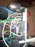
So I read here about using a bridge diod in its place,but it didn't ex plane how to wire it. Well I bolted my new bridge diod to the heat sink, used the 2 prongs that weren't marked +or - for the same 2 wires that went into the old diod, pluged it in, and in a second or two smoke was coming from the diod connections.:shocking:

I thought well you dummy you have to get the power out of the diod into the heatsink....So I bolted a wire to the heatsink and tried it on the + and - post of the diod with the same smoking results on both.

I dont know if what i did fried the diod or if i'am still doing something wrong.I have another diod to try if I knew for sure how to wire it.

Thanks for any help
 

Attachments

  • 20161024_111158.jpg
    20161024_111158.jpg
    133.6 KB · Views: 59
  • 20161024_111315.jpg
    20161024_111315.jpg
    137 KB · Views: 61
To avoid these ads, REGISTER NOW!

jdrider

New member
Joined
Oct 13, 2016
Messages
1
Location
Central Saskatchewan
It looks to me that the charger just used 2 button type diodes in its original state which means it uses a center tapped transformer. You are trying to wire it with a bridge rectifier that is not what you want. I also see a circuit board which means it is an automatic charger and will not put power out to leads unless a battery with some voltage is hooked up. These chargers will not spark the leads if touched together like chargers of old did. The reason it does not work may be in the circuit board and not a diode issue at all.
 

Infinia

Banned
Joined
Oct 2, 2016
Messages
845
Location
SoCal
I"d question your assumption about if the old rectifier diodes were the problem. The difference between V does not mean bad . The diodes usually fail shorted E.g. they will show continuity both ways. Disconnect the old diodes from the transformer* and re-test. with an ohm meter. note the direction to determine the output polarity E.g common cathode or plus side/. Don't ever power up stuff if youre not sure what you've done is 100% it may have multiple problemos now.

* I see you never disconnected the old diodes, so if they are bad, they still are in the circuit. ~no bueno
 
Last edited:
OP
P

passinthru

Active member
Joined
Feb 28, 2012
Messages
30
Location
S.W.Pa.
I"d question your assumption about if the old rectifier diodes were the problem. The difference between V does not mean bad . The diodes usually fail shorted E.g. they will show continuity both ways. Disconnect the old diodes from the transformer* and re-test. with an ohm meter. note the direction to determine the output polarity E.g common cathode or plus side/. Don't ever power up stuff if youre not sure what you've done is 100% it may have multiple problemos now.

* I see you never disconnected the old diodes, so if they are bad, they still are in the circuit. ~no bueno

The old diods were disconnected, that's just the jumper wire that I was useing still connected. I had to make a double female jumper for the new diod. Sorry for the confusion.

I generally didn't think the diod were bad because they were only working one way like they should,and the v wearn't that far off but I didn,t know what else to try. I will ohm out the old diods and let you know.

I did have it hooked to a battery with a v meter when I plugged it in, but it didn't read anything in the short time it was on.

Any suggestions on were to go from here,or to how to properly wire the diod.

Thanks
 

Infinia

Banned
Joined
Oct 2, 2016
Messages
845
Location
SoCal
IDK what the original problem was or the symptoms if any.

Diode check and polarity is clearly the 1st thing, is it common cathode?
Do the regular trouble shooting E.g. is the transformer putting out AC power with the secondary open or diodes out, should read ~15 VAC RMS to center tap or 30VAC across both windings. w/o working from a schematic its basically shooting in the dark.
 
OP
P

passinthru

Active member
Joined
Feb 28, 2012
Messages
30
Location
S.W.Pa.
IDK what the original problem was or the symptoms if any.

Diode check and polarity is clearly the 1st thing, is it common cathode?
Do the regular trouble shooting E.g. is the transformer putting out AC power with the secondary open or diodes out, should read ~15 VAC RMS to center tap or 30VAC across both windings. w/o working from a schematic its basically shooting in the dark.

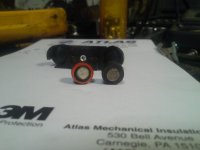
Sorry IDK what common cathode is ,but its a button diod one side black and one side red.
Ohmd them out +lead on red 17.000 =+lead on black 1.415
2nd diod- +lead on red open -- + lead on black 1.750

It was working good one day and the next it wouldn't charge.I check it on a battery and it wasn't putting out anything.
I tore it apart and replaced the circuit breaker which was burnt {welded} closed, I was getting ac v out of the transformer but couldn't find and power after the diods.
 

Attachments

  • 20161024_164519.jpg
    20161024_164519.jpg
    129.6 KB · Views: 27
Last edited:

Infinia

Banned
Joined
Oct 2, 2016
Messages
845
Location
SoCal
please google "diode testing with a multimeter, after you understand that google "common cathode" under images.


a diode has an anode and cathode, find out which side your two are tied together on the output side. this will tell us how to hook the bridge up plus or minus. you can verify this by using the multimeter on the replacement bridge to double check your work.

The 1st diode is bad from your numbers. The band on the diode always signifies the cathode side. so positive on cathode will show high ohms to anode on a conventional DMM and low on reverse. this checks your 2nd diode as being correct.
I would suggest replacing both with a 50A bridge since theyve probably experienced the same surge current that fused the broken circuit breaker.
 
Last edited:

Larryjones

Well-known member
Joined
Oct 11, 2015
Messages
494
Location
WV
I believe my diods are bad,there suppose to test over .5 and mine are at .472
What? Volts? Amps? Whatever, that isn't a precision piece of equipment and .472 should be within tolerances. Your pictures seem to be showing a lot of carbon traces, I suspect something is burned out other than the rectifier.
 
To avoid these ads, REGISTER NOW!

dogdog

Well-known member
Joined
Nov 15, 2011
Messages
12,711
I think the OP needs to understand the old diode configuration and then figure out if he should use the positive (+) or Negative (-) output if that "new bridge" rectifier he have.... if the diodes are smoking most likely he is some how grounding it.

That means he needs to find out where the center tap is going to in that power supply.
and also where the output of that old diode is going to..... before making the decision.

That is why "Infinia" post #9 suggested.

He can also test the output of the rectifier without any +/- leads hooked up if there is a voltage it's good, usually it's about .7 volt lower than the AC input.
 

dogdog

Well-known member
Joined
Nov 15, 2011
Messages
12,711
this should be verified with a multimeter (if the OP knows how to use one properly) but, from the thread I posted: ...center tap is to meter usually...all he should have to do is take the two leads from the tformer as follows: "Two connections are AC (transformer) and two connections are plus/ minus. Leave the minus terminal on the bridge UNconnected
Leave the wiring hooked from the meter to the transformer unmolested, that is shown as the "center tap" in the diagram"

Yes in that configuration if the + is used, the center tap is the reference, and it will be ground.... if the Negative is used the center tap will be the positive. without him posting the model / schematic .... it's hard to tell.... how the those old diodes are used.

Signs that give you clues are how the center tap wire is connected. if it goes to ground then, the most likely the diode output is positive, and if that is the case something else might be shorting in the circuit board and burning the diodes (old and new) Hence he should test without anything hooked up to, just to isolate the component and issue area.

Or OP could've just hooked up that rectifier incorrectly.... dunno. not there just taking a wild guess.
 
Last edited:
OP
P

passinthru

Active member
Joined
Feb 28, 2012
Messages
30
Location
S.W.Pa.
a diode has an anode and cathode, find out which side your two are tied together on the output side[QUO[/QUOTE]TE

I think the OP needs to understand the old diode configuration and then figure out if he should use the positive (+) or Negative (-) output if that "new bridge" rectifier he have.... if the diodes are smoking most likely he is some how grounding it.

That means he needs to find out where the center tap is going to in that power supply.
and also where the output of that old diode is going to..... before making the decision.
Thanks everyone for your help. Between all of you I am starting to get a grasp on this.

The old diods had the red cathode side against the heat sink.

The center tap is going to the meter.

And I had it wired with one wire from the transformer going into the(-) on the new diod.:lol_hitti In my defense I thought the wave symbol was a messed up negative symbol so used the other 2 for my input:dunno:

The heat sink is tied into the circuit breaker with the (+) battery cable.
So even though the (-) side of the old diod was against the heat sink I want to tie the (+) of the new one to the heat sink ??
 
OP
P

passinthru

Active member
Joined
Feb 28, 2012
Messages
30
Location
S.W.Pa.
Re: Update

Hi all, I want to thank everyone who tried to help me in my confused state.

I believe the problem is in the circuit board as some of you suggested , but with my pi**poor diagnostics who would know ?

First I doubled checked the old diods with my good meter,and they checked good. I cleaned them up and put them back in.

Second I took a better look at the center tap wiring, there are two wires coming off it. One is going to the circuit board and the other into the charge/start switch and then back into the meter.

Well I switched it to start and it worked, I don't suppose I'll have any of the smart capability's but at least I can use it.
That was a lot of messing around for the sake of pushing a switch,but it wasn't a total loss at least I learned a little about diods:thumbup:
 

Attachments

  • 20161026_153607.jpg
    20161026_153607.jpg
    134.6 KB · Views: 14
  • 20161026_151638.jpg
    20161026_151638.jpg
    135.8 KB · Views: 12
  • 20161026_123136.jpg
    20161026_123136.jpg
    141.3 KB · Views: 12

Infinia

Banned
Joined
Oct 2, 2016
Messages
845
Location
SoCal
good deal
Isnt it amazing that fiddling with switches and connectors often fixes older forgotten gear.
I reckon you knocked off or scratched thru enough corrosion somewhere.

Now onwards to "fix" the PCB > check or replace more connections, learn how to test / identify PNP & NPN transistors and replace 2or 3 electrolytic caps and you'll be golden.
 
Last edited:
To avoid these ads, REGISTER NOW!
Top Bottom