To avoid these ads, REGISTER NOW!

Built A Gantry Crane

f150skidoo

Well-known member
Joined
Dec 29, 2012
Messages
1,206
Location
Ontario, Canada
For those who followed my pusher box build would know that I don't have my skid steer at my house to do my heavy lifting during the winter months
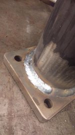
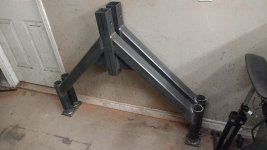
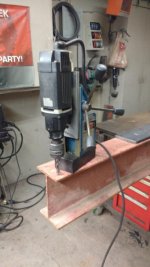
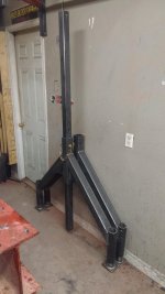
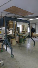
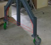
(Nov 15-Apr 15). So I built a gantry crane so I don't have to break my back lifting stuff, The crane is 9' between the legs. Its adjustable from 8-10 feet tall, and is rated for 3,000 lbs ( casters are the weak link). The H beam is W8x18, The a frame consists of 3x3 .188" tube with 2.5" SCH. 80 were the caster are mounted, and 2.5" .250 tube for the height adjustment. The crane will be very handy for my next project that I'm going to start in a few weeks. Ill give you guys a hint for what it is, the cylinder will push 100,000 lbs.
 

Attachments

  • IMG_20161127_091459910.jpg
    IMG_20161127_091459910.jpg
    147 KB · Views: 566
  • IMG_20161130_155837293.jpg
    IMG_20161130_155837293.jpg
    145.4 KB · Views: 588
  • IMG_20161201_125125769.jpg
    IMG_20161201_125125769.jpg
    145.6 KB · Views: 593
  • IMG_20161202_193203638.jpg
    IMG_20161202_193203638.jpg
    143.7 KB · Views: 598
  • IMG_20161203_111305404.jpg
    IMG_20161203_111305404.jpg
    145.6 KB · Views: 610
  • IMG_20161205_103626173.jpg
    IMG_20161205_103626173.jpg
    141.3 KB · Views: 938
To avoid these ads, REGISTER NOW!

MJD1

Well-known member
Joined
Dec 28, 2014
Messages
607
I would run a piece of flat bar, like 3/8" x3" on the side of the legs, above the casters, to prevent spreading. Outside of that, should work good.
 

metalhead212121

Well-known member
Joined
Mar 21, 2010
Messages
2,898
Dare I ask what the final cost was in materials??

I reason why I ask is because I've priced them out new and used on CL and I'm in shock of the prices. I've thought to myself "I can build one cheaper." Granted I KNOW you have to factor in the price of a welder, having the ability to lay a SOLID bead, the electricity FOR the welder, a mag drill press........
 

readhead

Well-known member
Joined
Dec 8, 2012
Messages
6,180
Location
Durango, Co.
As usual some pretty fine work. How do you raise the beam? I would agree about something spanning across above the castors. I have no doubts about your welds but any dynamic stresses could cause one of the legs to deform and fail.
 

WoodWorkers

New member
Joined
Dec 9, 2016
Messages
1
Great Build! You mentioned the Casters were the weak link? I have a similar project I'm working on and I believe my top plates for the casters were a 4"x4-1/2" and the casters I bought hold about 1,000 lbs each for a total of 4,000 lbs, shouldn't that be enough for the 3,000 lb capacity? I found them online at Caster Barn I believe.

http://www.casterbarn.com/MEDIUM-DUTY-6-X2-POLYURETHANE-WHEEL-SWIVEL-CASTER-p/md6x2pis.htm

Anyways keep up the good work!
 

Heavy Metal Doctor

Well-known member
Joined
May 26, 2010
Messages
5,417
Location
Mason Dixon Line
Great work! The ready made gantry I bought at work is nearly identical design, though different dimensions. It has tabs welded on the leg frames and the uprights to use a come-along to raise and lower it.
 

1wook

Active member
Joined
Feb 22, 2014
Messages
42
Location
Central MN
Nice! I'm looking forward to the press brake build.

You could use your floor jack to lift the beam when you decide you need to.
 

chruler

Well-known member
Joined
Oct 31, 2014
Messages
1,508
Location
Vermont
Another fine job. Some day, I'll have a garage again and will get going on some projects.
 

ovrrdrive

Well-known member
Joined
Sep 13, 2015
Messages
642
Location
Central Florida
Love the design of that... I might copy it from you.

I would worry about the legs being a failure point though. Did you consider either gusseting the legs or even using a tie-bar to keep them from spreading?

Edit. Attached pic
 

Attachments

  • Capture.JPG
    Capture.JPG
    58 KB · Views: 241
Last edited:

jimgood

Well-known member
Joined
Aug 4, 2014
Messages
2,394
Location
Marshall, VA
Love the design of that... I might copy it from you.

I would worry about the legs being a failure point though. Did you consider either gusseting the legs or even using a tie-bar to keep them from spreading?

Edit. Attached pic
They are gusseted. Take a closer look at the pic of the legs against the wall.

Really nice work. I like that you can disassemble it and get it out of the way when not in use.
 

zmotorsports

ALLIANCE MEMBER
Joined
Oct 20, 2009
Messages
21,400
Location
Northern Utah
Nice job. At least yours breaks down and fits inside your shop. My next door neighbor has a huge one 25' tall by 30' wide right in his front yard.:dunno: 
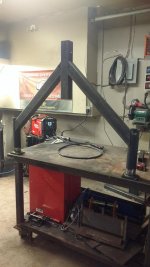
Makes for a beautiful piece of yard art and really adds to the property value.:shocking:

Mike.
 

hh76

Well-known member
Joined
Nov 9, 2010
Messages
3,450
Location
NE Wisconsin
Great Build! You mentioned the Casters were the weak link? I have a similar project I'm working on and I believe my top plates for the casters were a 4"x4-1/2" and the casters I bought hold about 1,000 lbs each for a total of 4,000 lbs, shouldn't that be enough for the 3,000 lb capacity? I found them online at Caster Barn I believe.

http://www.casterbarn.com/MEDIUM-DUTY-6-X2-POLYURETHANE-WHEEL-SWIVEL-CASTER-p/md6x2pis.htm

Anyways keep up the good work!

Keep in mind that the load won't always be balanced between all four. And if the load moves, the load on the individual casters can vary greatly.

It's amazing how handy the crane is once you have it. I don't need to lift extremely heavy items often, but it helps with positioning work, hanging parts, and all kinds of other things you wouldn't think of until you have the option.
 

ovrrdrive

Well-known member
Joined
Sep 13, 2015
Messages
642
Location
Central Florida
They are gusseted. Take a closer look at the pic of the legs against the wall.

Really nice work. I like that you can disassemble it and get it out of the way when not in use.

I saw the gussets at the top, that's why the pic I attached shows them at the bottom where the welds to the pipe are. I'm sure it's plenty strong for his intended use, it just seems to me that under a heavy load the legs could spread a little and cause a failure point there. Just seems the angles would cause force pulling them out.

Like I said, I'm sure it's fine.
 

readhead

Well-known member
Joined
Dec 8, 2012
Messages
6,180
Location
Durango, Co.
hh76 has kind of clarified my point. It is conceivable that a swinging load at one end of the beam could transfer all of the load into one castor. Connecting the two legs would minimize a chance of failure.
 
To avoid these ads, REGISTER NOW!

1wook

Active member
Joined
Feb 22, 2014
Messages
42
Location
Central MN
With the materials he used there is absolutely no need for more bracing or structure.

You guy's that are advocating for this a way over analyzing this. For reference take a look at a production made one, one that the company has to assume the liability your worried about.
 

readhead

Well-known member
Joined
Dec 8, 2012
Messages
6,180
Location
Durango, Co.
Not the same design. There is not an extra joint in the leg and they used larger tube. Skidoo is an excellent fabricator and it will probably work fine. I'm sure he knows the limits of his work and will be careful.
 

lakeroadster

Well-known member
Joined
Jan 19, 2015
Messages
5,166
Location
Central Colorado
With the materials he used there is absolutely no need for more bracing or structure.

Agreed.

Just for a quick sanity check I used the material data and dimensions that f150skidoo listed and created a CAD model, then ran FEA on it. So the model is similar, but not identical.

The deformation of the vertical side uprights under a load is greater than the bending of the legs, caster to caster, on the sides. Simply because the design of the lower leg sub-assembly is hell-for-stout, which is always a good thing on any lifting device.

Here's some screen shots of the FEA. Keep in mind the deflection that is shown is very exaggerated to give the user a visual of where the deflection is occurring. Max actual deflection for the offest loaded model was less than 1/4", and about 1/8" for the center loaded model. Both these @ the 3,000 lbs capacity f150skidoo stated.

Nice robust design f150skidoo :thumbup:


OP
F

f150skidoo

Well-known member
Joined
Dec 29, 2012
Messages
1,206
Location
Ontario, Canada
So to answer all the questions, to raise and lower it I'm just going to put a car jack under the uprights. My casters are rated at 1000lbs a piece so I figured at "rating" it at 3k would give me my safety factor. Thank you Lakeroadster for the CAD simulation of my crane to answer any question on the design. I was never concerned about the joint were the 3"x3" meets the 2.5" sch.80 since a coped 45 is a strong joint. The only part I was a little bit worried about is were the legs meet the upright tube, but I figured 1/4" plate gussets would suffice. And the 210 mp is working pretty well so far.
 

DaveIRL

Well-known member
Joined
May 21, 2016
Messages
319
MR LOADSTER

how do you find that package, I had ran an experiment where i tested a central point and a cantilever on a steel length, i then did the theory and the FEA on inventor, (dont like creo) and got different results, i asked the lecturer but he said those results were normal. EG

Newton load - ACTUAL THEORY FEA
1.991 22.4 22.9 13.3
2.991 33.2 34.7 22.7

so if i used the fea result (eg the 2.991 newton) for the previous load (1.991) it seems to right, does this happen to you, if so how do you rectify the situation.
have you ever tried creo
 

lakeroadster

Well-known member
Joined
Jan 19, 2015
Messages
5,166
Location
Central Colorado
Dave,

Verification Calculations: I have run std. beam calcs, then performed FEA using the same materials, loadings and constraints, with satisfactory results. The program is ANSYS based.

John
 
Last edited:

lakeroadster

Well-known member
Joined
Jan 19, 2015
Messages
5,166
Location
Central Colorado
Just curious about how much deflection on the diagonal hss until failure.

I re-ran the model to answer your query.

Using the offset load model:

If the load is increased to the point that the Safety Factor drops to 1, the model shows the web of the overhead beam has the highest stress.

The model shows the deflection of the diagonal hss at it's attachment to the vertical caster pipe is about 11/16", but again, even with all that deflection that's not the highest stressed component, the web of the overhead beam is.
_____________________________________________________________________________
Deformation


_____________________________________________________________________________
Stress

 
Last edited:

2oolhound

Well-known member
Joined
Dec 18, 2010
Messages
5,918
Location
BC Canada
I like the long legs on it so it can tip toe around things scattered around the floor in a busy shop. Tying the legs together would ruin that ability and it would lose a lot of manoeuvrability in a crowed area.
 

readhead

Well-known member
Joined
Dec 8, 2012
Messages
6,180
Location
Durango, Co.
Thanks for the second look. After looking at the design again I was satisfied that it was safe for the intended use. I guess the owner in me that pays huge liability premiums saw a concern. I should realize by now that mr. skidoo has a pretty solid grasp of fabrication skills.
 
OP
F

f150skidoo

Well-known member
Joined
Dec 29, 2012
Messages
1,206
Location
Ontario, Canada
In the few weeks since posting this thread I can tell you this is the handiest thing I've ever built. I had to do a small repair on a snow plow blade so I backed the truck under the crane and lifted the blade out of the bed. I also picked up 700 lbs of steel and my supplier used a 10 ton bridge crane to load me and my gantry unloaded my truck the same way it went in.
 
To avoid these ads, REGISTER NOW!
Top Bottom