To avoid these ads, REGISTER NOW!

Help - Wiring a Grinder Motor From 240v to 120v

FMC1959

Well-known member
Joined
Feb 9, 2014
Messages
2,319
Location
Montreal, Canada / Upstate NY
I just got this grinder
http://www.garagejournal.com/forum/showthread.php?p=6153863&posted=1#post6153863

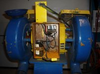
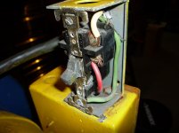
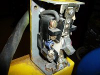
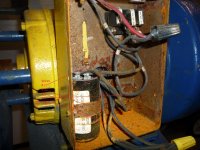
Below are pics of the wiring, pic # 6 has wire labeling. I have to assume it is currently wired for 240, it has a 20 amp 250v twist lock plug.

There are 6 wires coming out of the motor housing into this box.

#1 goes to the black Marette connector, connects to the red wire and then goes up to the on/off switch box.

#2, #3 and one of the unmarked black wires are connected with the yellow Marette connector and terminate there.

#4 goes to the terminal block and connects to terminal #1

the last wire of the 6, unmarked black wire goes to the capacitor (starter?), and then a wire from there goes to the terminal and attaches to terminal #2

Lastly, from terminal # 3, a wire goes up to the on/off switch box. Not sure of the significance but this wire leaving terminal #3, has a label you can barely see behind the red wire that has a # 3 and as it is halfway up to the on/off swath box it has a label #1.

Home wiring I have no issues but this motor wiring is not my expertise for sure. From checking some online motor diagrams, I think I need to split up wire #2, #3 and black wire in the yellow Marette. Take #3 and the black and connect it to the black Marette with wire #1 and the red wire.

Then take remaining wire #2 and connect it to the wire coming off of terminal #3 and going up to the on/off switch box.

I could be correct or completely off base on this. Anyone have expertise for this kind of wiring?

Thanks
 

Attachments

  • P1020642.jpg
    P1020642.jpg
    145.5 KB · Views: 52
  • P1020643.jpg
    P1020643.jpg
    144.8 KB · Views: 51
  • P1020644.jpg
    P1020644.jpg
    136.1 KB · Views: 50
  • P1020645.jpg
    P1020645.jpg
    135.8 KB · Views: 43
  • P1020646.jpg
    P1020646.jpg
    140.6 KB · Views: 43
  • Wiring.jpg
    Wiring.jpg
    146 KB · Views: 45
To avoid these ads, REGISTER NOW!

6PTsocket

Well-known member
Joined
Mar 12, 2014
Messages
4,593
I am having trouble seeng what you have there but I can tell you what is usually found in a capacitor start 120/240 motor. There are two run windings that are wired in parallel for for 120 and in series for 220 and the pair is across the AC line. There is a start winding that is wired in series with the internal centrifugal switch and the start capacitor and that string of parts is wired across the AC line. Flipping one of the run windings end for end reverses the motor direction. If your motor is too big it may have never been intended to run on 120. Some motors are not reversable. I hesitate to start telling you how to check out what what goes where by using an ohm meter when I am not even sure what you have. If you know what make and possibly model you have I think you should should approach it fron there and see if there is wiring information and if it can run on 120.

Sent from my SM-G900V using Tapatalk
 

454ragtop

Well-known member
Joined
Mar 24, 2008
Messages
5,011
Location
Carver, MA
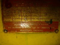
Aren't the instructions for wiring that motor on the tag, kind of cut off in the pic in your other thread?
 
OP
F

FMC1959

Well-known member
Joined
Feb 9, 2014
Messages
2,319
Location
Montreal, Canada / Upstate NY
Forgetting about wiring diagrams I saw online about 120/240 wiring for single phase motors, I tried to just look at it logically. Wire #1 & wire # 4 both go to the plug (through the switch box), on a 240 motor you have to hot leads carrying 120v. Also, many 240 motors have no need for a common/neutral wire, these must be wires # 2 & #3, which are tied off with no use. The 2 unmarked black wires I figure must be grounds.

So I was thinking in that case that wires #2 & #3 should go in the black Marette with the red wire, and wire #1 that is currently there, terminated for no use on the yellow Marette. along with the 2nd ground wire?

**** EDIT - Can these 2 unmarked black wires be grounds if one of them goes to the capacitor on the left side of the wiring box?
 
Last edited:
OP
F

FMC1959

Well-known member
Joined
Feb 9, 2014
Messages
2,319
Location
Montreal, Canada / Upstate NY
Aren't the instructions for wiring that motor on the tag, kind of cut off in the pic in your other thread?

I have vision trouble and couldn't make out anything on the tag. With a close up pic from my camera, you are correct, there are instructions.
 

Attachments

  • P1020647.jpg
    P1020647.jpg
    140.2 KB · Views: 66
  • P1020648.jpg
    P1020648.jpg
    144.2 KB · Views: 57
OP
F

FMC1959

Well-known member
Joined
Feb 9, 2014
Messages
2,319
Location
Montreal, Canada / Upstate NY
My guessing, logic and assumptions down the drain. Based on the tag on the motor....

First, take off the yellow Marette, and take wire #3 and tie it to the black Marette with wire #1 and the red wire going to the on/off switch.

Second, take wire #2 and connect it to wire #4, and this is where I am not 100% positive, but these 2 wires should be pigtailed with a wire from the pigtail going to terminal #1....just like wire #4 did previously.

That leaves the one lone unmarked black wire from the yellow Marette. Should it remain terminated or should it be connected somewhere?
 

6PTsocket

Well-known member
Joined
Mar 12, 2014
Messages
4,593
This is what I told you in the beginning of my last post. 1 and 3 are one end of the two run windings and 2 and 4 are the other ends. They were previously in series and you are now tying them in parallel for 120. Through the power switch they are tied across the 120.The black wire is one end of the start circuit consisting of the centrifugal switch inside the motor, the start winding and the start capacitor . One end is already connected to 1and 3 or 2 and 4. That is what you have to figure out. For starts, if you plug it in with the black wire disconnected and the motor only starts if you give the wheel a push, that proves my point. That wire is going to join 1 and 3 or 2 and 4 depending on which end of the start ciruit is already connected to the other end. Try it with the black wire off and if it does not self start and maybe hums until you spin it we will take it from there. Every time this issue comes up people are spouting all kinds of contradictory ideas. Some know and some do not. You, unfortunately have to decide who to listen to. The next step is people calling others trolls. I should probably avoid these discussions but I would like to help you if I can.


Sent from my SM-G900V using Tapatalk
 
OP
F

FMC1959

Well-known member
Joined
Feb 9, 2014
Messages
2,319
Location
Montreal, Canada / Upstate NY
This is what I told you in the beginning of my last post. 1 and 3 are one end of the two run windings and 2 and 4 are the other ends. They were previously in series and you are now tying them in parallel for 120. Through the power switch they are tied across the 120.The black wire is one end of the start circuit consisting of the centrifugal switch inside the motor, the start winding and the start capacitor . One end is already connected to 1and 3 or 2 and 4. That is what you have to figure out. For starts, if you plug it in with the black wire disconnected and the motor only starts if you give the wheel a push, that proves my point. That wire is going to join 1 and 3 or 2 and 4 depending on which end of the start ciruit is already connected to the other end. Try it with the black wire off and if it does not self start and maybe hums until you spin it we will take it from there. Every time this issue comes up people are spouting all kinds of contradictory ideas. Some know and some do not. You, unfortunately have to decide who to listen to. The next step is people calling others trolls. I should probably avoid these discussions but I would like to help you if I can.


Sent from my SM-G900V using Tapatalk

Thanks, I will give it a shot
 

6PTsocket

Well-known member
Joined
Mar 12, 2014
Messages
4,593
Just tie the ones together that the tag says to tie for 110VAC and you'll be good to go.
That is the two run windings. If the start circuit is not hooked up it will only run if given a push. Have you ever replaced a bad centrifugal switch or bad capacitor? A motor plate only covers the wires that need to be moved to change voltage or direction. They are not the only wires in the motor and if wires are not connected you can't ignore them just because they are not on the plate. There are multi speed fan motors that might have unused speeds and resultant unused wires. This is not one of those. However, the wire might just be a ground to the shell that should be going to the ground prong on the plug. If that is the case, you are right and the motor will run without it though it should be connected for safety. That is the trouble with remote diagnosis. A quick check with an ohm meter would show what goes where.

Sent from my SM-G900V using Tapatalk
 
OP
F

FMC1959

Well-known member
Joined
Feb 9, 2014
Messages
2,319
Location
Montreal, Canada / Upstate NY
I wired up 1&3 as well as 2&4. I need to step out for a while, when I come back, I'll put the nema 15 plug on and give it a try.

With the 240 wiring, wires 2 & 3 and a black unmarked wire were terminated. With there being 6 total wires, for 110v, with the terminated wires 2&3 being mated in parallel, would it not make sense to also mate or put in parallel the last remaining black unmarked wire to the other unmarked black wire currently connected to the capacator?
 

6PTsocket

Well-known member
Joined
Mar 12, 2014
Messages
4,593
I wired up 1&3 as well as 2&4. I need to step out for a while, when I come back, I'll put the nema 15 plug on and give it a try.

With the 240 wiring, wires 2 & 3 and a black unmarked wire were terminated. With there being 6 total wires, for 110v, with the terminated wires 2&3 being mated in parallel, would it not make sense to also mate or put in parallel the last remaining black unmarked wire to the other unmarked black wire currently connected to the capacator?
The 1to3 and 2 to4 came from you when you read the plate . I just interpreted that to be the normal parallel run windings for 120 operation. I would have expected something like 2 to4 with 1 to one side of the AC line and 3 to the other side, for 230 operation. Draw the two windings on paper to clarify the idea. For 230 the two windings are in series. The start circuit is the capacitor, the start winding and the centrifugal switch in series, across the AC line. The order does not actually matter but the capacitor and the centriugal switch are usually in either side of the start winding. It really helps to have a multimeter with an ohms range to see what goes where. Even the HF freebee is good enough.Right now you should at least have your two run windings in parallel across tha AC line. With everything else disconnected the motor should only start wth a push. Withourlt taking the motor apart and following the wires you are left to guess and that is not ideal. Thst is why a meter is invaluable.

Sent from my SM-G900V using Tapatalk
 
To avoid these ads, REGISTER NOW!
OP
F

FMC1959

Well-known member
Joined
Feb 9, 2014
Messages
2,319
Location
Montreal, Canada / Upstate NY
The 1to3 and 2 to4 came from you when you read the plate . I just interpreted that to be the normal parallel run windings for 120 operation. I would have expected something like 2 to4 with 1 to one side of the AC line and 3 to the other side, for 230 operation. Draw the two windings on paper to clarify the idea. For 230 the two windings are in series. The start circuit is the capacitor, the start winding and the centrifugal switch in series, across the AC line. The order does not actually matter but the capacitor and the centriugal switch are usually in either side of the start winding. It really helps to have a multimeter with an ohms range to see what goes where. Even the HF freebee is good enough.Right now you should at least have your two run windings in parallel across tha AC line. With everything else disconnected the motor should only start wth a push. Withourlt taking the motor apart and following the wires you are left to guess and that is not ideal. Thst is why a meter is invaluable.

Sent from my SM-G900V using Tapatalk

I see you are often on your phone, maybe you can't see the wiring I labeled, so I made a larger photo, hopefully it will show better. Both pics below are the same, the 2nd should be a bit larger. This is the wiring as I got it, setup for 230v.

First - I have tried undoing yellow connector and taking wire #3 and connecting along with wire #1 at black connector, along with the red wire going up to the switch.

Then I took wire #2 and connected to wire #4, before it connects to the terminal block. I left the unmarked wire from yellow connector, still terminated in yellow connector.

Result, does not work, no hum or anything from motor. Nothing happens when I try turn a wheel.

Second - I took the unmarked wire terminated in the yellow connector and connected to the capacitor, there is a 2nd tab right beside the other unmarked wire already connected to the capacitor.

Result, same as above, nothing.

Next, I am now going try the most basic connection, bypassing even the on/off switch. I will take wires 1&3 and connect it to the white terminal of a plug going straight to the wall and wires 2&4 connected to the black terminal. This should give what you stated above, power to the motor which could start on its own or need a turn and then should work. I will also clip a wire from the ground on the plug to a bare metal area on the wiring box to be safe. Lastly, in this scenario, wires 1#3 as well as 2&4 being swapped from black/white to white/black would only serve to change the direction of the motor, otherwise should work.

If this also fails, then I will rewire exactly as I got it in the picture, including putting the 20 amp 3 prong twist plug and try it with my generator. It is the only receptacle I have with a 240 twist lock, to test and make sure the motor even works.

BTW, I have an Ohm meter, just not very proficient with it....just know continuity and basic voltage. If someone has the patience to explain what and how to test, I can certainly try.
 

Attachments

  • Wiring-7.jpg
    Wiring-7.jpg
    106.9 KB · Views: 22
  • Wiring-8.jpg
    Wiring-8.jpg
    142.7 KB · Views: 15
OP
F

FMC1959

Well-known member
Joined
Feb 9, 2014
Messages
2,319
Location
Montreal, Canada / Upstate NY
This worked, sort of.

I plugged it in and the motor started turning on its own, but slowly....just guessing but a hundred rpm or so, looked like 2-3 revolution per second. It did this for abot 5-7 sec then blew the breaker.

The circuit is definitely viable, it is a 20 amp circuit I installed in my garage and because it is about 70 feet from the breaker box, I used 10 gauge wire to be sure it wouldn't overheat (although at 70 feet I believe 12 gauge would still be OK). The motor is rated at 13 amp but if it needs a "starter" to get it up to 1700 rpm, I can see the motor peaking over 20 amps struggling to get the rpms up without assistance.

For the heck of it, I tried a second time where I tried spinning up the wheels best I could, but same thing happened, maybe got an extra second or two before the breaker popped. Very difficult to get these big wheels spinning fast by hand.

I am going to try setting it up with the unmarked wires to the capacitor, where the 2 unmarked wires are connected to the capacitor and wires 2&4 are connected to the terminal bloc and from the terminal block to the plug.

Could be the switch is defective or also needs to be rewired for 120v...not sure.
 
OP
F

FMC1959

Well-known member
Joined
Feb 9, 2014
Messages
2,319
Location
Montreal, Canada / Upstate NY
I tried a variety of configurations, either it would go a few seconds a very low rpm and blow the breaker, or in some cases, nothing happened. In one of the wiring setups where it would turn slow then blow the breaker, I took of the side plate to have access to the grinding wheel. It is held on by a 1 1/2" bolt!!! I put a socket on it with my drill I got it spinning close to 2000 rpm, then remove the drill and socket and plugged it in. It went for 20-25 seconds, but then blew the breaker.

I am down to my last option. I am going to wire as I got it for 230v with the twist lock plug and try it on my generator, the only 230v twist lock receptacle I have. If this doesn't work then it is not a 120v wiring problem, but something else altogether.
 

pstemari

Well-known member
Joined
Jan 7, 2012
Messages
903
Location
Seattle
I am down to my last option. I am going to wire as I got it for 230v with the twist lock plug and try it on my generator, the only 230v twist lock receptacle I have. If this doesn't work then it is not a 120v wiring problem, but something else altogether.

Well, if you have an ohmmeter, then some basic tests are in order *before* applying power.

Based on the name plate, leads 1&2 are one of the run windings and leads 3&4 the other. Measure the resistance of each, with the leads disconnected from anything else, and verify that you have continuity and that the two resistances are roughly equal. The resistance should be a few ohms.

The leads coming out of the motor that are attached to the cap and starter switch should be the start winding. Verify that those also have continuity.

Then tie #1 and the switched hot together, and tie #2 to the neutral. Don't hook up any other wires. Turn it on and give it a spin. It should start up.

Switching white and black will have no effect on the direction. It should start in whichever direction you initially spin it.
 
Last edited:
OP
F

FMC1959

Well-known member
Joined
Feb 9, 2014
Messages
2,319
Location
Montreal, Canada / Upstate NY
Well, if you have an ohmmeter, then some basic tests are in order *before* applying power.

Based on the name plate, leads 1&2 are one of the run windings and leads 3&4 the other. Measure the resistance of each, with the leads disconnected from anything else, and verify that you have continuity and that the two resistances are roughly equal. The resistance should be a few ohms.

The leads coming out of the motor that are attached to the cap and starter switch should be the start winding. Verify that those also have continuity.

Then tie #1 and the switched hot together, and tie #2 to the neutral. Don't hook up any other wires. Turn it on and give it a spin. It should start up.

Switching white and black will have no effect on the direction. It should start in whichever direction you initially spin it.

Thanks, I will give it a shot tomorrow.
 

6PTsocket

Well-known member
Joined
Mar 12, 2014
Messages
4,593
Well, if you have an ohmmeter, then some basic tests are in order *before* applying power.

Based on the name plate, leads 1&2 are one of the run windings and leads 3&4 the other. Measure the resistance of each, with the leads disconnected from anything else, and verify that you have continuity and that the two resistances are roughly equal. The resistance should be a few ohms.

The leads coming out of the motor that are attached to the cap and starter switch should be the start winding. Verify that those also have continuity.

Then tie #1 and the switched hot together, and tie #2 to the neutral. Don't hook up any other wires. Turn it on and give it a spin. It should start up.

Switching white and black will have no effect on the direction. It should start in whichever direction you initially spin it.
Why are you making the test run with only only one run winding we know from the plate and you just stated that 3&4 are the other run winding. I don't disagree with anything you said. I would do as you but I don't know how familiar the OP is with test equipment and following the plate doesn't seem too risky. It occurrs to me that the cap might be a run cap and there is no centrifugal switch. They are usually a much lower value than a start cap but wired similarly. The extra winding and the run cap are across the AC. The OP has not posted in a while. We may be talking to ourselves

Sent from my SM-G900V using Tapatalk
 
OP
F

FMC1959

Well-known member
Joined
Feb 9, 2014
Messages
2,319
Location
Montreal, Canada / Upstate NY
Well, if you have an ohmmeter, then some basic tests are in order *before* applying power.

Based on the name plate, leads 1&2 are one of the run windings and leads 3&4 the other. Measure the resistance of each, with the leads disconnected from anything else, and verify that you have continuity and that the two resistances are roughly equal. The resistance should be a few ohms.

The leads coming out of the motor that are attached to the cap and starter switch should be the start winding. Verify that those also have continuity.

Then tie #1 and the switched hot together, and tie #2 to the neutral. Don't hook up any other wires. Turn it on and give it a spin. It should start up.

Switching white and black will have no effect on the direction. It should start in whichever direction you initially spin it.

Went into my garage and was going to try exactly as you said above, but first wanted to try something I found last night searching on the internet. The last wiring setup I had was identical to the one in the pic except wire #5 in the pic, one of the 2 unmarked black wires in my wiring, was on the 2nd clip of the capacitator, and the diagram has it connected with 1 &3.

Took all of 5 seconds to make this change, plugged it in and it started like a top! Runs smooth and sounds awesome. Now I just have to fix up all the wires properly and reconnect the switch and I will be grinding away.

pstemari, 6PTsocket and others who replied with assistance, thanks.
 

Attachments

  • Wiring-3.jpg
    Wiring-3.jpg
    99.1 KB · Views: 14

6PTsocket

Well-known member
Joined
Mar 12, 2014
Messages
4,593
Went into my garage and was going to try exactly as you said above, but first wanted to try something I found last night searching on the internet. The last wiring setup I had was identical to the one in the pic except wire #5 in the pic, one of the 2 unmarked black wires in my wiring, was on the 2nd clip of the capacitator, and the diagram has it connected with 1 &3.

Took all of 5 seconds to make this change, plugged it in and it started like a top! Runs smooth and sounds awesome. Now I just have to fix up all the wires properly and reconnect the switch and I will be grinding away.

pstemari, 6PTsocket and others who replied with assistance, thanks.
Glad it is running. That does not contradict what we have been saying. The capacitor, the start winding and the centrifugal switch are across the AC line. One end of the capacitor should go to AC. The other end of the cap goes into the motor to the start winding and then to the centrifugal switch and then to the terminal that you hooked up 2,4 and the other side of the AC line. Just for fun, when you shut off the grinder is there an audible click as it coasts to a stop? That would be the centrifugal switch opening, if there is one.

Sent from my SM-G900V using Tapatalk
 
OP
F

FMC1959

Well-known member
Joined
Feb 9, 2014
Messages
2,319
Location
Montreal, Canada / Upstate NY
Glad it is running. That does not contradict what we have been saying. The capacitor, the start winding and the centrifugal switch are across the AC line. One end of the capacitor should go to AC. The other end of the cap goes into the motor to the start winding and then to the centrifugal switch and then to the terminal that you hooked up 2,4 and the other side of the AC line. Just for fun, when you shut off the grinder is there an audible click as it coasts to a stop? That would be the centrifugal switch opening, if there is one.

Sent from my SM-G900V using Tapatalk

I'll need to pay attention, it takes about 2 minutes before it comes to a complete stop.
 
OP
F

FMC1959

Well-known member
Joined
Feb 9, 2014
Messages
2,319
Location
Montreal, Canada / Upstate NY
I checked and it takes a while to coast to a stop, but no clicking at any point. My 6" grinder which I have had for about 35 years has the very distinct click you mention, as well I have heard it on other motors.
 

6PTsocket

Well-known member
Joined
Mar 12, 2014
Messages
4,593
I guess it is possible that your motor is capacitor run, rather than capacitor start. With capacitor start , the switch is closed, connecting the start winding and start caoacitor when you turn the grinder on. As soon as the grinder gets going weights swing out and open the switch, disconnecting the capacitor and start winding. When you shut it off you hear the click when the start switch closes again, for the next start. With a capacitor run circuit there is no switch and the capacitor is a much smaller value. That winding in the motor and the capacitor are always connected across the line. Run capacitors are a much smaller value. A start capacitor might be 470mfd and a run capacitor might be 10mfd. Some motors have both and you will see two pods on top of the motor. Grinders don't start under load so they generally don't need that much starting torque. Enjoy your grinder.

Sent from my SM-G900V using Tapatalk
 
To avoid these ads, REGISTER NOW!
Top Bottom