To avoid these ads, REGISTER NOW!

36' Span possible with steel beam or LVL

C91x

Well-known member
Joined
Aug 26, 2015
Messages
267
Location
Prescott Valley
Any experts want to give me some advice.

Want to build a loft in my new pole barn. In my old 36x48 I had a upstairs loft that was 12x36 but had a post in the middle of the span. I don't remember the size I-beam i used but there was zero deflection up there. I want to see if anyone else has done a clear span of 36'.

Loft will be 36x10
dead load around 10-20 and live load 40psf

Last resort is paying an engineer but for just a simple storage loft it seems overkill
 
To avoid these ads, REGISTER NOW!

ducatithunder

Well-known member
Joined
Dec 15, 2016
Messages
317
Location
Annapolis-ish, MD
I just had ibeam joists speced for my build in MD. We have a 25snowload. They loaded these to 30ppsf on a 2/12 pitch. My span is 28ft but 32'6" overall length of beam. I was going to use LVLs but they were expensive i had to double them up due to there weight they would have sagged more then the ibeams. I got 14" schedule 90 flanged I beam joists that will work. At $4.50 a LF they are mich cheaper then LVL. These would be on 16" centers.

Hope that helps. Go to your local lumber supply and talk to the engineer. He will be able to pit somthing togeathet for you. It will give you options and will let you know what works and doest. They will run the calcs and tell you if it passes or fails. Best part is it will be free bc they want to sell you the beams.
 

padroo

Well-known member
Joined
Nov 25, 2011
Messages
564
Location
Chesterton, In.
My house has 22 inch X 36 foot floor trusses, free span, one foot on center. They make a springy floor but work. I don't remember what the floor load calculation was. They are made out of 2 X 4s and weigh 225 lbs each.
 

matt_i

Well-known member
Joined
Mar 14, 2008
Messages
10,728
Location
SE Michigan
The steel is great strength but its a pain to connect with all over. I believe LVLs are made up to 40' long via special order.

Whatever you choose its going to be very heavy. Forklift highly recommended for rigging.

Also the loads of the framing + storage have to be transferred back into the ground. Posts are one option, but also have to either notch the post or build enough vertical structure on the side of it to transfer the loads.
 

The Tool Tyrant

ALLIANCE MEMBER
Joined
Dec 19, 2011
Messages
2,182
Location
Bonita, Ca. (San Diego)
Well, yes...but can you live with a little 'spring' in your floor? A 36' clear span will be springy no matter which way you go...steel or wood. If you're just utilizing the loft for storage you probably don't really care, but if you want to use it for living/ office space the springiness may be bothersome. In my previous life I was a framing carpenter/contractor for 32 years and I found that steel beams always seemed to be springier than PSL, LVL or glu-lams. Here is a link to a guide on Parallam beams: http://www.woodbywy.com/trus-joist/parallam-psl-beams/ Scroll down and download the 'Specificers Guide' for 2.2E 20"-24" beams. They can be ordered in lengths up to 66'. Good luck.
 

LX-Markham

Well-known member
Joined
Apr 27, 2013
Messages
2,929
Location
Markham, Ont.
A properly designed (engineered) steel beam will not be springy. It will be a big beam however, probably around 21" or so.

Long span like that, plus 40 psf LL is going to attract a lot of load. You will need posts like matt suggested, and likely footings.
 

theoldwizard1

Well-known member
Joined
Feb 22, 2011
Messages
43,169
Location
SE MI
Steel beam, of course. Go to a structural steel company and the will just look it up in their table.

LVL or wooden I-bean, maybe. Go to the lumber yard and they will have tables.

Third choice is a parallel chord truss.

flat-roof-trusses.jpg


These can be made out of wood or steel and will hold a HUGE amount of weight. You can actually "hang" it using the top chord from the tops of the posts, but you loose headroom on the first floor. The problem is, depending on the a post may be required under each on of these trusses. Forget trying to hang one of these from the top plate/girt.

Also, do NOT think you can nail/lag bolt a couple of 2x12 to the posts on the back wall and then run joist from there ! You will need another beam/truss.


EDIT : Quick check. Any span over 30-32' is going to need a truss.
 
Last edited:

driftpin

Well-known member
Joined
Dec 22, 2016
Messages
11,260
Location
Miami-Dade/Broward Co. Florida
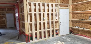
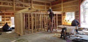
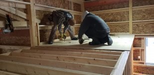
I had built a loft which isn't full height above my two-car garage. That's all we could afford to do, we kept the same roof instead of bumping it higher. The garage is a nominal 20' x 22' & the loft is a nominal 13' x 22'. We used a structural engineer, and I asked for a capacity capable of supporting the weight of multiple motorcycles. The engineer did the calcs and gave us a front-of-the loft steel box beam, 1/2" wall thickness, 4" x 8" welded into steel flitch plates cast into the masonry side walls. The beam is sandwiched on both sides by a 2" x10" (ripped to 8" to match the box beam dimension) wood beam to allow easier attachment of the loft floor joists, which are 2" x 8" & 18" o.c. It's sheathed with 3/4" plywood. The structure has no stairs to access the loft, not-even an attic 'pull-down' stairs. For access, I use an A-frame ladder, but since it's used for storage, it's not an everyday trip I make.

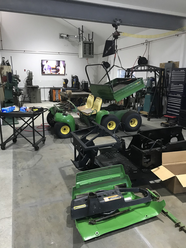
One concession I made to getting heavy things up & down to/from the loft, I thought about what would make an easy load-lifter? The roof ridge beam is also a 1/2" wall thickness box beam with plates welded to it for the ceiling joists. If it was an I-beam girder I could use an overhead trolley on the lower surface flange of the beam, but due to the box construction, that was out. I even went as-far as-to buy a short-web I-beam with the idea to bolt it to the underside of the box beam at the ridge, but I discovered that between the I-beam girder, the trolley, and the rigging, I would lose precious headroom, and be unable to lift much over 3' in height onto the loft deck. So I went a different way. I adapted a 'cherry-picker.' I'll post that up in a new thread.

Yes, you may be able to use the free design skills of your local supply store, but here in Florida, you don't get a permit for structural work like that without having a professional engineer (P.E.) submitting sealed plans for the structural calcs. Considering what's at stake, you don't need a catastrophic failure so using the services of a structural engineer is a matter of safety for you and anyone around the structure. I am a plans examiner and a Life Safety Code inspector, and I've seen a lot of stupid, dangerous things done by amateurs and professionals.

In the event of a failure of a structural component, the plaintiff attorneys supoena the design documents, including the plans review, the inspections, product approvals for the components right-down to the fasteners, and then a forensic engineering team reviews them with compliance to the building code at the time of construction. This is typical of what they may find: contractors substituting cheaper fasteners or structural materials which are not rated for the level of weather exposure or load can cause the entire load-bearing system to fail, possibly with tragic results. Protect yourself, get the professional services, it's $ well-spent.
 

Attachments

  • image.jpg
    image.jpg
    144.4 KB · Views: 224

maxpower_hd

Well-known member
Joined
Apr 17, 2015
Messages
2,230
Location
Massachusetts
Just go to a local lumber yard that sells the I-beams and LVLs and tell them what you are wanting to do. And maybe a quick drawing and they will help you spec them or tell you it cannot be done.

I know I used to work at a wholesale lumber place years ago and and the lengths of the LVL and I-Beams back then were upwards 60'. I don't know what the allowable spans are without support but we used to unload them off the trains. They would typically be cut to length to order before they went out to the retailers. And they were new way back then. 1990'ish.

I have 14" I-beams 16" OC spanning 24' without supports and the LVL's are 3x16" spanning 28' without support. I read one span chart for the I-beams if they are 12" OC they may be able to go 35' 10" span. But it depends on some other factors.

The engineers at the yard I bought my stuff from specified what I needed for free and even gave me engineering documentation to bring to the building department.
 

ard

Well-known member
Joined
Feb 16, 2015
Messages
4,391
Location
Sierra Foothills... California
Any of the companies that sell LVL/TJIs or engineered lumber will have a tech support number you can call. Or as posted above, local full service lumber yards (not H, L or M) will be able to look it up.

I just gave a quick look and the longest lvls Ive seen in their published design manuals are 32 ft spans.

Id use steel.
 
Last edited:

ard

Well-known member
Joined
Feb 16, 2015
Messages
4,391
Location
Sierra Foothills... California
Driftpin have the right answer. A flitch beam (a.ka.a flitch plate beam).

Lvl2.jpg

Stonger/better than a steel I beam?!?

from wiki

Due to the high cost of labor, use of this type of beam has greatly declined. The advent of high-strength engineered lumber which uses modern adhesives and lower cost wood fibers has rendered this system largely obsolete. For example, compare the capacity of 2 beams spanning 18 feet: the allowable strength of a 3½ʺ × 11¼ʺ laminated veneer lumber (LVL) member has a tabulated allowable applied load of 398 plf (pounds per linear foot); compare this to a 2 × 12 flitch beam constructed of ½ʺ steel plate with two laminations of #2 SPF with an allowable applied load of 386 plf.

36 foot clear span is FAR...
 
To avoid these ads, REGISTER NOW!

kwb

Well-known member
Joined
May 1, 2009
Messages
1,771
Location
PNW
I spanned 42' with a 36" box beam which functionally is about the same as the parallel chord truss.

I built it in the air-- I would not do it that way again. I should have built it on the floor and then lifted it up to position.

Steel would be big and a quick guess about $1800 and a PITA to connect to. When I did mine the steel/wood cost difference was enough to make me do wood. At the end I worked for about a nickle an hour on the savings.
 

wssix99

Well-known member
Joined
Mar 2, 2011
Messages
5,161
Location
Chicago, IL
I have an engineered 100 psf 20' X 12' deck held up with a 12" X 6" PSL beam and need to have a column mid-span. Since you are looking at roughly twice the span with half the strength, I can confidently conclude that you won't be able to make it with a stock homogeneous manufactured wood beam.
 

cgrutt

Well-known member
Joined
Mar 4, 2016
Messages
8,273
I think it has already been mentioned but I'd recommend an engineer and flitch plate(s). Recently quoted job with flitch plates and they weren't that expensive all things considered. Span was only about 25' though. Not sure that matters, hence get an engineer, LOL. Good luck!
 

matt_i

Well-known member
Joined
Mar 14, 2008
Messages
10,728
Location
SE Michigan
300#/LF W16x40 A36

I get a W18 x 46 lb/ft.

In W16 I'd have to have a 50#/ft version.

This is very serious steel, on the order of a 1 ton steel beam, 16 to 18" tall....

I think the cost on this is going to get out of hand pretty quickly without center support posts.

In regards to the flitch beam, this is an OK idea when the wood members are continuous from one span to the other. However the thought of getting a 36' 2x material is not going to happen. The problem in analyzing then becomes that the moment is not continuous thru the wooden member and the analysis starts costing more than the beam. LVLs are possible in that length, but why bother doing all of the work with flitching if you could just order one more LVL.

Best cost for the buck idea I have here would be 2 support posts and roughly 12 feet of span.
 

readhead

Well-known member
Joined
Dec 8, 2012
Messages
6,180
Location
Durango, Co.
The advantage of flitch plates is being able to assemble a beam in a confined space. This is not a good application here. In this case one 1/2" x 12" plate will weigh over 700 pounds. I have retrofitted steel beams into old buildings and sometimes installing a single beam is not practical. With a properly designed joint connection a beam can be installed in multiple pieces. We have had to hand carry beams into buildings because of access issues.

Obviously at least three smart guys have come up with three different steel beam sizes based on a best guess. Without knowing the actual tributary loads the calculations are a shot in the dark. The OP needs to consult an engineer to properly size a beam. The material and design of the beam should take into consideration what kinds of skill and equipment are available to accomplish the installation.
 

WNYflyer

Well-known member
Joined
Sep 13, 2009
Messages
2,119
Location
Lockport, NY
Be very careful using simplistic published capacities for steel beams. In the footnotes and text there is typically somewhere where they say the tables are based upon the compression flange of the beam (top flange for simple spans) is assumed continually laterally braced or laterally braced at some maximum interval. In most cases the lateral bracing is provided by structural members framing into the side of the beam which typically forms a horizontally diaphragm with the floor/roof deck, be it plywood, steel deck/plate, concrete slab, etc. The horizontal diaphragm in turn must also be laterally stable which is typically provided by vertically braced frames, vertical shear walls of masonry, wood, etc.

If the beams are not laterally braced correctly by a complete system then use of the simplistic tables for final design is wrong. The devil is in the details and notes typically somewhere in the tables/notes.
 

bczygan

Well-known member
Joined
Nov 4, 2009
Messages
22,002
Location
DETROIT! Arsenal of Scrappers
be very careful using simplistic published capacities for steel beams. In the footnotes and text there is typically somewhere where they say the tables are based upon the compression flange of the beam (top flange for simple spans) is assumed continually laterally braced or laterally braced at some maximum interval. In most cases the lateral bracing is provided by structural members framing into the side of the beam which typically forms a horizontally diaphragm with the floor/roof deck, be it plywood, steel deck/plate, concrete slab, etc. The horizontal diaphragm in turn must also be laterally stable which is typically provided by vertically braced frames, vertical shear walls of masonry, wood, etc.

If the beams are not laterally braced correctly by a complete system then use of the simplistic tables for final design is wrong. The devil is in the details and notes typically somewhere in the tables/notes.

this!
 
OP
C

C91x

Well-known member
Joined
Aug 26, 2015
Messages
267
Location
Prescott Valley
Thanks for all the help guys. I'll talk to my local builders source and see if there engineer can come up with something. But weighing the cost it appears I might be going with a center support
 

Meadowron

New member
Joined
Jul 31, 2020
Messages
1
Location
Meadowmtn
Hello All , and Thanks for excepting me . I am looking into making a Cantilever beam system to app support . Have local saw mill was going that rough cut nearby , can’t dig to much drop to quick was going to raise grade 3 feet and use as counterweight on top of beam which will be on hard ground . Many ideas it’s a 2 story log house with basement and unsure ground below . It 34 feet long so was going to see the longest beam saw mill can cut and that’s my start . Guess it’s a reverse cantilever but have rocket flagstone soil so much weigh can be added with backfill . Was thinking if I added steel plate to beams at closet edge would help with counter weight . Just a thought added to ideas from this site Thanks And Have a Great Weekend !💜🌎
 

dcg9381

Well-known member
Joined
Jun 20, 2018
Messages
11,762
Location
Austin, TX
that should be your FIRST resort, not last. A 12x36 clear span mezzanine is significant.


There are beam calculators for span online. I've used them for smaller mezzanines.

Many suppliers have an engineer in house that can help you select the right product.

I have a house with one 40' beam. It holds up a roof, non-snow load. I have it braced 4 places across, so it's not free span. Finding someone to transport it can be problematic.. Trusses seem to be much more common.


> http://www.etcs.ipfw.edu/~dupenb/ET_200/Beam Design.pdf

This 404s.


> flitch beam

I haven't seen this before.. This looks like the right idea to me!
 

Craig Balzer

Well-known member
Joined
Sep 21, 2005
Messages
863
Location
Colorado Springs
Up Front: I didn't read any other posts in this thread so this may be useless

I have a mezzanine that is 8' wide running the depth of the building (36'). Width of large shop is 48' wide and 36' deep.

I attached a bunch of photos that will address how I did this better than I can describe in words. Hope this helps

I haven't loaded anything on the deck yet so I don't have a report on stability / flex; it seems pretty solid when I walked on it and I didn't sense any flex. I did specify the 2x10's to be spaced closer together than the GC recommended. I think it amounted to 3 additional spans. It helped that I was essentially bridging the future bathroom and the Dirty Room. The 4 canterlever-ed spans form the landing for then staircase -- Craig
 

Attachments

  • 20200219_151009.jpg
    20200219_151009.jpg
    152 KB · Views: 53
  • 20200219_151808.jpg
    20200219_151808.jpg
    153.5 KB · Views: 56
  • 20200220_231022.jpg
    20200220_231022.jpg
    144.3 KB · Views: 52
  • 20200220_151205.jpg
    20200220_151205.jpg
    153.2 KB · Views: 53
  • 20200220_231130.jpg
    20200220_231130.jpg
    152.9 KB · Views: 49
  • 20200221_102040.jpg
    20200221_102040.jpg
    146.5 KB · Views: 42
  • 20200221_145316.jpg
    20200221_145316.jpg
    150.1 KB · Views: 52

Plastikosmd

Well-known member
Joined
Nov 17, 2016
Messages
1,254
Steel
Spec it for an additional ton or so and had chainfall for other projects
 
Last edited:
To avoid these ads, REGISTER NOW!
Top Bottom