To avoid these ads, REGISTER NOW!

Is there an electric engineer in the house?

87bob

Well-known member
Joined
Mar 4, 2013
Messages
47
Location
Franklin IN
I have a British made milling machine (Beaver) that is 220 V 3 Phase. It came with a manual motor switch that switch was equipped with an adjustable AMP setting. The old switch is toast! The model/style of switch is no longer available. The main spindle motor is rated at 3 horsepower. My delimea is that while I know the AMP safety range on the old switch I don't know what the new one should be set for. In addition this machine also has a coolant pump on it that recieves it's power through this same switch. How can I figure this out? I don't want to under protect both of these motors and take the chance of burning something up! For the time being I intend to only run the main spindle motor till I can figure out what I need to do.

Any help would be appreciated! Thanks!
 
To avoid these ads, REGISTER NOW!

LS6 Tommy

Well-known member
Joined
Dec 27, 2013
Messages
26,162
Location
Northern NJ
What does the motor plate say?

I'm not an electrical engineer, but I did stay in a Holiday Inn once...

Tommy
 

wyliesdiesels

Well-known member
Joined
Aug 14, 2012
Messages
20,038
Location
Modesto, CA
Im not an EE either but i am an electrician.

What u describe sounds like a motor starter.

And do u have 3 phase at your place?

Also, 220v is not available in the US. Does the motor nameplate say 220v or 240v?
 

Wes J

Well-known member
Joined
Mar 13, 2016
Messages
457
Location
Peoria, IL
Lots of old machines say 220. It used to be the standard.

Your overload protection should be sized for the wire you have. Motors allows you to have a larger fuse or breaker than the size of the wire or the FLA on the motor plate. Check the NEC.

I'd use 2 switches. Say 10 amps for the spindle motor and 5 for the coolant motor.
 

wyliesdiesels

Well-known member
Joined
Aug 14, 2012
Messages
20,038
Location
Modesto, CA
Lots of old machines say 220. It used to be the standard.

Your overload protection should be sized for the wire you have. Motors allows you to have a larger fuse or breaker than the size of the wire or the FLA on the motor plate. Check the NEC.

I'd use 2 switches. Say 10 amps for the spindle motor and 5 for the coolant motor.

The overloads on motor starters are sized based on motor nameplate FLA NOT wire size.

Wire for motor circuits is sized 125% of NEC FLC tables which sizes the wire way over the FLA rating of the motor.
 

mm08822

Well-known member
Joined
Jan 13, 2012
Messages
6,005
Location
NJ
First thing needed - more info:

Pics of both motor nameplates
Pic of fried switch/starter
Pics of external wiring arrangement between components
Pic(s) of any schematic
Does coolant pump have internal overload protection?
What do you mean by "adjustable amp setting"? a speed controller or ???

How long have you had this running before it died?

May be a good candidate for a 3 phase vfd with 3 wire control - but details first.
 

Wes J

Well-known member
Joined
Mar 13, 2016
Messages
457
Location
Peoria, IL
The overloads on motor starters are sized based on motor nameplate FLA NOT wire size.

Wire for motor circuits is sized 125% of NEC FLC tables which sizes the wire way over the FLA rating of the motor.

That's a starting point. You can have up to 200% of FLA if required for starting.
 

mm08822

Well-known member
Joined
Jan 13, 2012
Messages
6,005
Location
NJ
That's a starting point. You can have up to 200% of FLA if required for starting.

Wylie is correct.
You are confusing external motor overload protection values with motor feeder overload protection values and even then it is up to 250% for inverse time trip breakers and up to 800% for instantaneous trip breakers.
 
Last edited:

matt_i

Well-known member
Joined
Mar 14, 2008
Messages
10,730
Location
SE Michigan
I am no EE, I am a ME for whatever that is worth (not much!), but here goes:

3hp x 750W/hp / 240vac = 9.375 A

Using the full 3hp is unlikely in a milling machine. I would fuse for 7.5-8A and run with that.

Are you using actual 3 phase to power this or is it fed from a rotary converter or ??... I ask because if there are overload heaters that detect phase-loss and you are on phase conversion these won't help out...in fact they will trip with great consistency.

Imo, coolant systems on machine tools are for enclosed machines like CNC machines. Running coolant on a manual machine is like splashing sticky fluid all over everything including the floor on purpose. Just run slower and hand-apply coolant/lube with a trigger-squirt bottle if water-based or a chipbrush if oil-based.
 
Last edited:

CheapCharlie

Member
Joined
Mar 29, 2012
Messages
12
He did say 3 phase right? Multiply that by 1.73
9.32125 x 1.73 = 15.97A


Sent from my iPhone using Tapatalk
 

mm08822

Well-known member
Joined
Jan 13, 2012
Messages
6,005
Location
NJ
He did say 3 phase right? Multiply that by 1.73
9.32125 x 1.73 = 15.97A


Sent from my iPhone using Tapatalk

Fixed more betterer:
3hp x 746w/hp /240v/1.73 x 1.25(for losses. efficiency) = ~6.75A min

Why do we care anyway? The nameplate is the credible source.
 

laser3kw

Well-known member
Joined
Nov 17, 2012
Messages
7,276
Location
northen IL
Fixed more betterer:
3hp x 746w/hp /240v/1.73 x 1.25(for losses. efficiency) = ~6.75A min

fixed glaring deficiency:
3hp x 745.7 w/hp /240v/1.73 x 1.25(for losses. efficiency) = ~6.735 A min
 
To avoid these ads, REGISTER NOW!

mdd1986

Well-known member
Joined
Jun 7, 2013
Messages
52
Wylie is correct.
You are confusing external motor overload protection values with motor feeder overload protection values and even then it is up to 250% for inverse time trip breakers and up to 800% for instantaneous trip breakers.

I'm an EE and this is correct. Here is how it its done:

I usually size breakers between 175%-200% of the Full load current for the motors. I almost never specify instantaneous trip breakers these days. Fuses (Dual element time delay type) is 175% max. This is all in table 430.52 of the NEC.

SINGLE MOTOR APPLICATION:
Wire size is always 125% of the Full Load Current (NEC 430.22). This assumes that the motor is in a "continuous" duty application (Runs for 3 hours straight or more). I very rarely have a situation where this is not the case but most of my applications are large commercial projects. There are certain exceptions to this which I have never really used. Refer to NEC 430.22(E) and table 430.22(E).

MULTIPLE MOTOR APPLICATION:
This is probably the application here where there are two or more motors. You would size the OCPD for the largest motor the same as you would for a single motor. However the other smaller motors would be summed as 100% of the full load current of the motor (NEC 430.62). The same is true for the conductors (NEC 430.24)

Also as stated in NEC 430.6(1), motor FLA tables in the NEC shall be used over nameplate date for OCPD and conductor sizing. However multi-speed motors, and motors with lower speed and high torque use nameplate data.

So, for a 3HP motor and 1HP motor for the cooling or whatever its for:

3HP = 9.6A @ 230V 3phase (NEC Table 430.250)
1HP = 4.2A @ 230V 3phase (NEC Table 430.250)
(9.6*200%)+(4.2*100%) = 23.4A go to 25A breaker. 30A breaker is also acceptable.
(9.6*125%)+(4.2*100%) = 16.2A use #12 wire.

There are other things in the code that talk about different types of overload protection and controllers. I'm not sure what the situation is here but this where I would start.
 
Last edited:
OP
8

87bob

Well-known member
Joined
Mar 4, 2013
Messages
47
Location
Franklin IN
First thing needed - more info:

Pics of both motor nameplates
Pic of fried switch/starter
Pics of external wiring arrangement between components
Pic(s) of any schematic
Does coolant pump have internal overload protection?
What do you mean by "adjustable amp setting"? a speed controller or ???

How long have you had this running before it died?

May be a good candidate for a 3 phase vfd with 3 wire control - but details first.

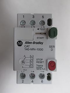
One of the previous owners by passed the manual start switch. I found it burnt. Manual motor start switchs can have a adjustable AMP setting to prevent motor overloads. The switch has the companies name and the adjustable AMP settings nothing else. The spindle motor is rated at 3hp. I know nothing about the pump motor, it in the enclosed base. I'll try to post some pictures this weekend.
 
OP
8

87bob

Well-known member
Joined
Mar 4, 2013
Messages
47
Location
Franklin IN
I'm an EE and this is correct. Here is how it its done:

I usually size breakers between 175%-200% of the Full load current for the motors. I almost never specify instantaneous trip breakers these days. Fuses (Dual element time delay type) is 175% max. This is all in table 430.52 of the NEC.

SINGLE MOTOR APPLICATION:
Wire size is always 125% of the Full Load Current (NEC 430.22). This assumes that the motor is in a "continuous" duty application (Runs for 3 hours straight or more). I very rarely have a situation where this is not the case but most of my applications are large commercial projects. There are certain exceptions to this which I have never really used. Refer to NEC 430.22(E) and table 430.22(E).

MULTIPLE MOTOR APPLICATION:
This is probably the application here where there are two or more motors. You would size the OCPD for the largest motor the same as you would for a single motor. However the other smaller motors would be summed as 100% of the full load current of the motor (NEC 430.62). The same is true for the conductors (NEC 430.24)

Also as stated in NEC 430.6(1), motor FLA tables in the NEC shall be used over nameplate date for OCPD and conductor sizing. However multi-speed motors, and motors with lower speed and high torque use nameplate data.

So, for a 3HP motor and 1HP motor for the cooling or whatever its for:

3HP = 9.6A @ 230V 3phase (NEC Table 430.250)
1HP = 4.2A @ 230V 3phase (NEC Table 430.250)
(9.6*200%)+(4.2*100%) = 23.4A go to 25A breaker. 30A breaker is also acceptable.
(9.6*125%)+(4.2*100%) = 16.2A use #12 wire.

There are other things in the code that talk about different types of overload protection and controllers. I'm not sure what the situation is here but this where I would start.
Than you for the very serious reply. I'm going to post some pictures this weekend.
 

laser3kw

Well-known member
Joined
Nov 17, 2012
Messages
7,276
Location
northen IL
is the item you are talking about something like this:
71LF15nzyaL._AC_UL320_SR240,320_.jpg

and the "dial" in the lower left is the "AMP" selection your are speaking of?
 
OP
8

87bob

Well-known member
Joined
Mar 4, 2013
Messages
47
Location
Franklin IN
is the item you are talking about something like this:
71LF15nzyaL._AC_UL320_SR240,320_.jpg

and the "dial" in the lower left is the "AMP" selection your are speaking of?

Yes but I also need to know what to set the AMPS for. My switch has a range of 3.8-6.0
 

manwithtools

ALLIANCE MEMBER
Joined
Aug 24, 2015
Messages
13,989
Location
Lebanon, TN
You have a switch that is not commonly available anymore. Most applications such as yours now will use separate start and stop push buttons wired to a contactor and overload such as laser3kw posted a picture of.

The setting of your amps on your switch is dependent on the motor name plate information. I suspect the setting should be close to 6 amps, the nameplate will tell us more.
 
Last edited:

mm08822

Well-known member
Joined
Jan 13, 2012
Messages
6,005
Location
NJ
So will you take pics of the motor nameplates?
How is the motor start/stopped if the switch was bypassed?
Is speed control accomplished mechanically?
Was the coolant pump motor hooked in parallel to the lathe motor through the one set of overloads?
 

matt_i

Well-known member
Joined
Mar 14, 2008
Messages
10,730
Location
SE Michigan
Were I in your shoes, I'd come up with a good, used NEMA Size #0 motor starter of 120vac coil and a 50VA transformer. I'm not big on wiring 240vac thru operator stations but its just a personal preference, the 120vac could also be useful for other things like a LED sewing machine light.

Use the maintained (?) on-off switch to control that, setup overload heaters, or bypass the N.C. contact if you are on a rotary converter. If the on-off pushbuttons are momentary then you need an auxiliary contact to setup the "seal circuit".

3_wire_control_01.jpg
 

laser3kw

Well-known member
Joined
Nov 17, 2012
Messages
7,276
Location
northen IL
to the OP - 87Bob

to make sure you get the right info:
In your opening post you stated
I have a British made milling machine (Beaver) that is 220 V 3 Phase. It came with a manual motor switch that switch was equipped with an adjustable AMP setting. The old switch is toast! The model/style of switch is no longer available. The main spindle motor is rated at 3 horsepower

SO you are, at this time, going to continue to operate the 3 hp mill on 240v 3 phase? plus the coolant pump is also 3phase?
 

wyliesdiesels

Well-known member
Joined
Aug 14, 2012
Messages
20,038
Location
Modesto, CA
to the OP - 87Bob

to make sure you get the right info:
In your opening post you stated


SO you are, at this time, going to continue to operate the 3 hp mill on 240v 3 phase? plus the coolant pump is also 3phase?

Who knows if the OP even has 3 phase....
 
OP
8

87bob

Well-known member
Joined
Mar 4, 2013
Messages
47
Location
Franklin IN
to the OP - 87Bob

to make sure you get the right info:
In your opening post you stated


SO you are, at this time, going to continue to operate the 3 hp mill on 240v 3 phase? plus the coolant pump is also 3phase?

YES all items are 3 phase
 

mburrus

Well-known member
Joined
Nov 15, 2014
Messages
235
Location
Miami, Fl
i am an ee. post pics of the motor name plate, switch name plate, and switch overall. sounds like a motor starter...
 
OP
8

87bob

Well-known member
Joined
Mar 4, 2013
Messages
47
Location
Franklin IN
i am an ee. post pics of the motor name plate, switch name plate, and switch overall. sounds like a motor starter...

The motor plate is very hard to read and can't be seen in a photo it is rated a 3 Horse Power with 220 3 Phase, 6 horse power at 440 3 Phase. The current switch is shown in post 28 I believe. This device as I understand (with an exposed switched and internal AMP regulator) are not commonly used any longer. I have found numerous 220V 3 Phase switches. So if I went that way what is the device called that I would use to regulate the current to prevent a motor overload? I have 15 AMP breakers 12 gauge wire but I need a device to regulate a current flow up to a max of 6 AMPS.
 

wyliesdiesels

Well-known member
Joined
Aug 14, 2012
Messages
20,038
Location
Modesto, CA
As has been said u need a motor starter with an overload relay that is set for 6a or use the device posted above by laser3kw

Are u sure the motors dont have integral overload protection? Maybe the small one does.
 
Last edited:

mm08822

Well-known member
Joined
Jan 13, 2012
Messages
6,005
Location
NJ
If you really want to protect each motor independantly, you need to get the nameplate fla's of each motor and size the two ol's for each motor. Just Read the fla's for the 220v connections if you cant take pic.

Otherwise 1 ol for both motors in parallel set at 5+ is a false sense of protection.
 
OP
8

87bob

Well-known member
Joined
Mar 4, 2013
Messages
47
Location
Franklin IN
If you really want to protect each motor independantly, you need to get the nameplate fla's of each motor and size the two ol's for each motor. Just Read the fla's for the 220v connections if you cant take pic.

Otherwise 1 ol for both motors in parallel set at 5+ is a false sense of protection.

Yes thank you, I agree completely. That is the way the machine is wired now. It has two of the switches I posted the pictures of, each has a different rating. I saw a Utube video
that gave me good information. I have reached out to the Manufacture who's product is shown in the video by email. I should hear from them in the coming week. Thank you all who responded!
 
To avoid these ads, REGISTER NOW!
Top Bottom