To avoid these ads, REGISTER NOW!

Adding Garage Outlets

L5wolvesf

Well-known member
Joined
Dec 4, 2011
Messages
1,831
Location
Northern AZ
Hi All,

#1 I am not an electrician and I don’t speak electricity as fluently as many of you do. #2 I want to add some outlets to my workbench area which has none right now. Running extension cords to use my drill press or grinder etc is a PITA. The garage is detached from the house.

There is a light switch along the wall where the workbench is attached. More specifically it is a pair of switches that operate ceiling outlets, next to one of the man doors. One switch operates 2 florescent (2 bulb) fixtures on a 20 amp circuit breaker. I plan to upgrade those to 3 LED (2 bulb) fixtures. The other switch currently operates a pair of outside flood lights which are going to be moved to a completely different location. That switch will then operate 3 LED (2 bulb) fixtures. None of that is a problem for me to handle.

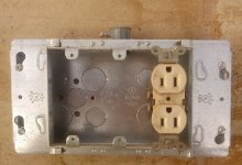
What I want to do is change the box to a 3 gang with one of the spaces being a 2 plug outlet as pictured. That outlet would mostly be used to run an extension cord outside when I am doing a project outside the garage. Also, from the right side of the 3 gang box run wire about 5 feet (half way down the workbench) to another 2 plug box. So I would end up with 4 additional plugs. Since I wouldn’t be using more than one tool at a time I don’t think I would be overloading the circuit. I think the same would apply if I were operating one tool, a friend was operating another and the lights were on. Correct me if I am wrong on that.

Doing the work isn’t a problem; I need to know what to do, how to wire in the outlets and where to attach wires to make this work correctly.

Hopefully I’ve included enough info, if not ask and I will answer.

I thank you very much.
 

Attachments

  • 2 gang.jpg
    2 gang.jpg
    63.4 KB · Views: 77
  • 3 gang.jpg
    3 gang.jpg
    128.8 KB · Views: 74
To avoid these ads, REGISTER NOW!

wyliesdiesels

Well-known member
Joined
Aug 14, 2012
Messages
20,061
Location
Modesto, CA
Can u pull the switches out of the boxes leaving the wires attached and take a pic please.

Need to know if there is a neutral in the box.
 

AntonLargiader

Well-known member
Joined
Nov 20, 2016
Messages
1,372
Location
Charlottesville, VA
Tell us what wires come into the existing switch box. You may have only three black wires (hot, switched to ceiling, switched to floods) but if you have a neutral (white) in there you can get another outlet from it.
 

SuzukiGS750EZ

Well-known member
Joined
Apr 26, 2012
Messages
3,273
I'll be watching this thread because as a NON licensed electrician, i have a pretty good idea as to what i would do but i don't want to give you non professional advice, so i will sit down and watch :). What i will say is that you will need a run of NM-B from the outlet you want to replace down to the other outlet through conduit. One set of hot, neutral and ground screws (will need a pigtail for ground) will come in from your switch (for 120v) and the other set of screws will attach your NM-B to go down to the next outlet. I go the extra step and run a length of electrical tape around the screws after i'm done installing the wires for peace of mind. The other thing i could see you doing would be to run a double rocker switch in your current box and then running your first outlet in the second area that you would free up instead of running a 3 switch box. Just a thought...
 
OP
L

L5wolvesf

Well-known member
Joined
Dec 4, 2011
Messages
1,831
Location
Northern AZ
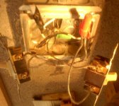
The pic as WD requested. And, I didn’t recall from before that the one white/neutral wire is just taped off. Not sure what that is about but I’m gonna wire nut it before I put things back in the box.

Correction: The switch on the left is for the ceiling outlets (fluorescents); the right is for the floods.

Re Anton’s question: There are 2 sets of wires coming into the box each set has a ground, a neutral (white) and a black.
 

Attachments

  • in 2 gang.jpg
    in 2 gang.jpg
    61.1 KB · Views: 150
Last edited:

AntonLargiader

Well-known member
Joined
Nov 20, 2016
Messages
1,372
Location
Charlottesville, VA
That's a pretty bad pic; very hard to see colors. The white balance is way off (like you're shooting tungsten under daylight WB).

Are they individual wires or is it two Romex cables? It sort of looks like one white is taped as black? I would expect to see a black splitting to both switches and then a black from each switch going back up. That's if they used individual wires. If Romex, then they probably repurposed one of the whites as a black? Hard to see in that pic. Can you describe what each wire does?
 

wyliesdiesels

Well-known member
Joined
Aug 14, 2012
Messages
20,061
Location
Modesto, CA
yes horrible pic.

Can u take a pic with natural light and without the flash? Also move the red wire nut lower as well as the camera so we can see the back of the box.

How many jacketed cables do u have in the box? only 2?

Since theres a black taped neutral u probably have switch legs which complicates things.
 
OP
L

L5wolvesf

Well-known member
Joined
Dec 4, 2011
Messages
1,831
Location
Northern AZ
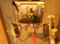
Sorry about the pic quality; **** cell camera, no camera flash, shot with flash light. Fluorescents in garage are off at the breaker. Also the wire routing makes it hard to set the wires so I can get a good image of what is going where. If this pic isn’t good enough I’ll rearrange the rat’s nest of wires and get things so they’re easier to see.

The 2 jacketed cables (Romex) going into the box are routed as follows:
Cable on left
-Black wire to switch on left (fluorescents), on lower screw connector.
-White wire not connected to anything just taped.

Cable on right
-Black wire to switch on right (floods), on upper screw connector.
-White wire w/black tape partly around it (a black taped neutral). Black wires from the other screw connectors are wired nutted (red) together.

Grounds are grounded.
 

Attachments

  • in 2 box.jpg
    in 2 box.jpg
    135.9 KB · Views: 120

wyliesdiesels

Well-known member
Joined
Aug 14, 2012
Messages
20,061
Location
Modesto, CA
Ok that was a good enough description.

u only have 2 NM-b cables in the box so they are acting as switch legs(power in on one black, switched power out on black and white(taped black).

U need a neutral for the outlets and in your case that would only be possible if the spare white was hooked to neutral in the light j box or one of the cables is 3 conductor.

Do u have a multimeter wiggy or some kind of test tools?

Need to check the spare white and see if u have 120v between it and the hot feed.

Otherwise, u will have to run an additional cable to get the needed neutral.
 
OP
L

L5wolvesf

Well-known member
Joined
Dec 4, 2011
Messages
1,831
Location
Northern AZ
Ok that was a good enough description.

u only have 2 NM-b cables in the box so they are acting as switch legs(power in on one black, switched power out on black and white(taped black).

U need a neutral for the outlets and in your case that would only be possible if the spare white was hooked to neutral in the light j box or one of the cables is 3 conductor.

Do u have a multimeter wiggy or some kind of test tools?

Need to check the spare white and see if u have 120v between it and the hot feed.

Otherwise, u will have to run an additional cable to get the needed neutral.

No 3 conductor in there. The light j box has a load of wires into it, I'd hate to see inside it, but I'll probably have to. The wires to the floods are going to be removed. I could use that for the additional cable.

I have a small HF multimeter. A "wiggy" well none that I would attach to an electrical circuit. I also have a no contact voltage detector. I'll check the spare white for voltage in the AM.

I really appreciate the help on this.
 

wyliesdiesels

Well-known member
Joined
Aug 14, 2012
Messages
20,061
Location
Modesto, CA
No 3 conductor in there. The light j box has a load of wires into it, I'd hate to see inside it, but I'll probably have to. The wires to the floods are going to be removed. I could use that for the additional cable.

I have a small HF multimeter. A "wiggy" well none that I would attach to an electrical circuit. I also have a no contact voltage detector. I'll check the spare white for voltage in the AM.

I really appreciate the help on this.

Just in case "wiggy" went over your head here is what it is. Wiggy is actually a brand name. Solenoid tester is the name of the type of device:

6610VT1%20Wiggy%20Voltage%20Tester.jpg
 
OP
L

L5wolvesf

Well-known member
Joined
Dec 4, 2011
Messages
1,831
Location
Northern AZ
Might be easier to find power up above and drop a 'fresh' piece of EMT to a new 2 gang for your new receptacles.....

The EMT only goes to the top of the block wall - just Romex from there to the junction box - about 6 to 7'. I really need an outlet to be where the switches are, but I get what you are saying. Running more Romex is something I figured I might have to do.
 
To avoid these ads, REGISTER NOW!
OP
L

L5wolvesf

Well-known member
Joined
Dec 4, 2011
Messages
1,831
Location
Northern AZ
I checked the white/neutral wire that is not connected to anything (toward the top of this pic with wire nut instead of tape now) with a voltage detector (chirper) and there is power there. I also reset the wiring so it is a bit easier to see where which wire goes (see pic). It is as I described it earlier.

Also, turns out I do have a small Wigg(ish) devise – don’t judge. :dunno:
 

Attachments

  • inside 2gang.jpg
    inside 2gang.jpg
    63.3 KB · Views: 51
  • Wiggish.jpg
    Wiggish.jpg
    52.1 KB · Views: 33

wyliesdiesels

Well-known member
Joined
Aug 14, 2012
Messages
20,061
Location
Modesto, CA
Checking the wire with an inductive tester doesnt tell us what we need to know.

Need to know if its a neutral or hot wire.

Need to use a tester that reads voltage and report back your findings.

Test from the white to the hot thats common between both switches..
 

tyme2par4

Well-known member
Joined
May 16, 2016
Messages
571
Location
NH
Without solid test results, we can't say for sure. But my guess is that the taped white wire is the hot wire coming into the box. The capped white wire can be used as the neutral, but you'll have to connect it to the neutral wire in the overhead box.
So the white wire would go to the neutral screw of the outlet, then you would need a short piece of black wire to go from the hot screw, to the wire nut that currently holds 2 blacks and the taped white wire.
Again, this is an educated guess based off of what the pictures look like.
 
OP
L

L5wolvesf

Well-known member
Joined
Dec 4, 2011
Messages
1,831
Location
Northern AZ
Checking the wire with an inductive tester doesnt tell us what we need to know.

Need to know if its a neutral or hot wire.

Need to use a tester that reads voltage and report back your findings.

Test from the white to the hot thats common between both switches..

From the white (which is not connected to anything) to the junction where 3 wires are wire nutted reads 110 volts on my mini-Wiggy.
 

TonkaJoe

Well-known member
Joined
Dec 19, 2014
Messages
410
Location
Southern ON, Canada
I would assume you have a panel in your garage if it is detached from your house?. I know this can be done by adding wire to existing switches or outlets etc as long as you don't exceed 80% of your circuits maximum amperage, but if you do have a panel out there have you considered adding a completely new circuit dedicated to your needs that is always hot and not run by a switch?. In my opinion this would simplify what you're looking to do. Anyway, its only a thought.. lots of smart individuals here with previous experience to get you the right help otherwise!.

Sent from my SM-G903W using Tapatalk
 
OP
L

L5wolvesf

Well-known member
Joined
Dec 4, 2011
Messages
1,831
Location
Northern AZ
I would assume you have a panel in your garage if it is detached from your house?. I know this can be done by adding wire to existing switches or outlets etc as long as you don't exceed 80% of your circuits maximum amperage, but if you do have a panel out there have you considered adding a completely new circuit dedicated to your needs that is always hot and not run by a switch?. In my opinion this would simplify what you're looking to do. Anyway, its only a thought.. lots of smart individuals here with previous experience to get you the right help otherwise!.

Sent from my SM-G903W using Tapatalk

The main panel to the property (house and garage) is mounted on the outside of the garage. I do have spaces in the panel, but working inside the panel is outside my experience and knowledge level. But having wall outlets on a separate circuit would be good with me.

This got me thinking about another situation I have. Could I repurpose another light circuit which has a single switch in a really bad spot (which I would remove completely) that currently has 2 florescent (2 bulb) fixtures on a 20 amp circuit breaker? My plan has been to upgrade that row of lights to 3 LED (2 bulb) fixtures.

So a question regarding my lighting circuit(s) is: Is 9 LED (2 bulb) fixtures, (what the planned lighting would eventually be), on one 20 amp circuit breaker be too many?
 
OP
L

L5wolvesf

Well-known member
Joined
Dec 4, 2011
Messages
1,831
Location
Northern AZ
Without solid test results, we can't say for sure. But my guess is that the taped white wire is the hot wire coming into the box. The capped white wire can be used as the neutral, but you'll have to connect it to the neutral wire in the overhead box.
So the white wire would go to the neutral screw of the outlet, then you would need a short piece of black wire to go from the hot screw, to the wire nut that currently holds 2 blacks and the taped white wire.
Again, this is an educated guess based off of what the pictures look like.

Thank you - I pretty much get what you're saying. So this is one option I am considering. I just posted on another that came to mind.
 
OP
L

L5wolvesf

Well-known member
Joined
Dec 4, 2011
Messages
1,831
Location
Northern AZ
Heck no. Most LED 4' twin LEDs I see are around what, 40~50W? You could put 30 of those on a 20A breaker and not hit 15A.

That is really good to know – thank you.

So I went out to the garage to see what I have to work with if I have to tackle all the wiring at once. I also wanted to verify which circuit that the only wall plug in my vehicle work area is on. That outlet is on the opposite side of the shop where I want to add plugs, BUT it is on the circuit where I want to add outlets. They could have placed it on a similar light circuit just above it. WTF :dunno:

Because of the location of this outlet, near a corner, there are only 2 things I plug in there. The one I use most is my compressor (Craftsman 33 gallon, 120v 15 amp) and the blower for the wood stove which I rarely use. This is a good location for what I have on it but nothing more since it isn’t easy to access.

At this point would it help y’all to help me if I drew out a diagram of what is connected where?
 

AntonLargiader

Well-known member
Joined
Nov 20, 2016
Messages
1,372
Location
Charlottesville, VA
At this point would it help y’all to help me if I drew out a diagram of what is connected where?

It might even help you. Before I straightened out the basement wiring, I spent a lot of time staring at stuff trying to build a mental picture of what was really there and what could be changed so that things would make more sense. I never mapped it out on paper but in retrospect I think it really would have helped. I was dealing with about 15 circuits, some of which had really nonsensical mixes of things on them.
 
OP
L

L5wolvesf

Well-known member
Joined
Dec 4, 2011
Messages
1,831
Location
Northern AZ
It might even help you. Before I straightened out the basement wiring, I spent a lot of time staring at stuff trying to build a mental picture of what was really there and what could be changed so that things would make more sense. I never mapped it out on paper but in retrospect I think it really would have helped. I was dealing with about 15 circuits, some of which had really nonsensical mixes of things on them.

I get that - I'm gonna draw one up this weekend. Thanks
 
OP
L

L5wolvesf

Well-known member
Joined
Dec 4, 2011
Messages
1,831
Location
Northern AZ
Attached is the layout of the circuits in the work area of my garage. As best as I can tell the only things on circuit 2 (C2) are the 2 ceiling outlets indicated near the center of the area. Everything else is on circuit 1 (C1). That seems odd to me.

The outlets I originally inquired about adding are on the west side near the man door.

The lights and outlets in the storage area are on different circuits.

Thank you in advance for any thoughts and help on this.
 

Attachments

  • Garage Circuits.pdf
    124.7 KB · Views: 6
OP
L

L5wolvesf

Well-known member
Joined
Dec 4, 2011
Messages
1,831
Location
Northern AZ
Update: I’ve removed the flood light wiring from the junction box/ceiling outlet (C1). In the process I traced the wires from that box to the outlet by my desk. That wire also has the unboxed junction I indicated on the circuit layout.

Any input on how to proceed on adding some outlets would be appreciated.
 
To avoid these ads, REGISTER NOW!
Top Bottom