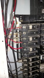
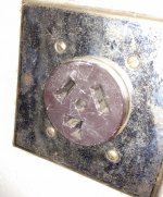
So the previous owner of our house installed a 240V outlet right below the breaker box in the garage. The odd thing is that the wires are run into the box, but only the common and ground are connected, not the hot wires, they are capped off. I assume they were hooked up at some point and then disconnected it before selling the house. Breaker box is fed by 200A and is a GE TLM3020C.
I am going to get a welder and will need a dedicated outlet for it when I use it. I am going to replace the plug in the wall with the correct style and I am getting a 50A GFCI dual pole breaker for the box to feed the new outlet. I am going to pull a permit as I obviously want this signed off on it. When we had the inspection done a couple years ago, it said the common/ground rail was overused on one side (and it clearly is). So I know I functionally could tie into the ground bus on the left side of the panel that has plenty of places and then put the breaker in the open space on the right, but will the inspector not sign off on it because of the overused right side? If so, can I expand the bus bar on the right side to clean some of that up?
My plan is new outlet wired via 12awg romex through the wall to the strain relief in the bottom of the breaker box, common and ground to left buss and black and red to each pole of the 240V breaker placed in the open spot on the right. The outlet is currently in one of the old work boxes, which I think that will work. Is this all functionally up to code?
TIA for any help!