
You are using an out of date browser. It may not display this or other websites correctly.
You should upgrade or use an alternative browser.
You should upgrade or use an alternative browser.
2 questions on this DP electric motor
- Thread starter dogdog
- Start date
wyliesdiesels
Well-known member
Does the nameplate say anything about reversing leads for cw and ccw?
Does the nameplate say anything about reversing leads for cw and ccw?
I don't think there are anything else other than those two pics.... I guess will have to remove the motor to take a closer look, it's in a corner blocked. That is why I snap the pic and ask the question first before moving all those stuff blocking it.
Milton Shaw
Well-known member
- Joined
- Feb 11, 2011
- Messages
- 4,838
The noise on turning by hand is probably from the start switch. Its switch parts cycle when the rpm reaches most of full speed and then those parts are set where they are not touching and quit making noise. Sounds like normal for the motor..
The noise on turning by hand is probably from the start switch. Its switch parts cycle when the rpm reaches most of full speed and then those parts are set where they are not touching and quit making noise. Sounds like normal for the motor..
Ok let me clarify.... It's a Jet 14" benchtop drill press... I unhooked the belt on the pulleys. Now when I spin the pulley attached to the motor, it squeals a little ..... Not sure if it is because it is something normal.... something with the shaft from over tighten belt for these years.... or just bearing related like grease dried up.... motor is manufactured in 1994.... drill press is lightly used.
Not sure what a start switch inside a motor is.... in this case...
The noise on turning by hand is probably from the start switch. Its switch parts cycle when the rpm reaches most of full speed and then those parts are set where they are not touching and quit making noise. Sounds like normal for the motor..
Oh you are referring to the centrifugal switch as in this video.... not sure if that squeals....I don't have problem with motor starting or humming, just squeals when no power is applied and I turned motor by hand.... but will check.
Dagny
Well-known member
yep rotating mechanism rubbing switch very common .
yep rotating mechanism rubbing switch very common .
I think you are right just confirmed.... took off the motor took off the switch put back the cover, spin it by hand, no squealing.....I am going to put some grease on that contact points betweem that spring washer and the non-metalic bushing. see if it helps... ... hope I can put it back together. it's going to be fun with that many pieces. what do normal people put to stop the squealing?
I am looking at this article found on the web.... can any one explain the differences between the forward and reverse wiring of the 110V?
http://www.metalwebnews.com/howto/elec-mtr/elec-mtr.html
http://www.metalwebnews.com/howto/elec-mtr/elec-mtr.html
American Locomotive
Well-known member
They put nothing, because the switch stops making contact when the motor is up to speed. Putting grease on it will probably just foul the electrical contacts.I think you are right just confirmed.... took off the motor took off the switch put back the cover, spin it by hand, no squealing.....I am going to put some grease on that contact points betweem that spring washer and the non-metalic bushing. see if it helps... ... hope I can put it back together. it's going to be fun with that many pieces. what do normal people put to stop the squealing?
They put nothing, because the switch stops making contact when the motor is up to speed. Putting grease on it will probably just foul the electrical contacts.
ok I think a pic tomorrow will better explains it... basically the non contact busing seems to push against a spring disc that have the contact points made out of tungsten or what not material... the bushing is push again the spring disk to make or break the contact I think... these two contact point does not have any electrical functions other than mechanical.
American Locomotive
Well-known member
Yes, but when the motor is at operating speed, the contact points pull away from each other. They only touch when the motor is stopped or at low speed.
In order to reverse the motor, you need to access the "start" winding. That diagram you show only shows the "run" winding wiring changed from series to parallel to accomodate the different voltages.
You have it apart, so have a look for it internally. That centrifugal switch is connected to the "start" winding, and the power needs to be reversed to that winding, to reverse the motor.
You have it apart, so have a look for it internally. That centrifugal switch is connected to the "start" winding, and the power needs to be reversed to that winding, to reverse the motor.
Ok, Thanks lilredex.... it worked.... flawlessly... on the test bench...
You are 100% right on the 4 wires they are double running coils for voltage 240/110 when in series/parallel....
Traced the wires into the coils.... the yellow have two lead (magnetic wires) crimping to it. took it out, separated the wiring. now it's reversing") just have to put everything back together nicely...
just have to put everything back together nicely...
using this diagram sort of and reversing the W3 coil makes it reverse.... will post more pics.

this posting...
http://www.practicalmachinist.com/v...please-wiring-switch-motor-257832/index2.html
You are 100% right on the 4 wires they are double running coils for voltage 240/110 when in series/parallel....
Traced the wires into the coils.... the yellow have two lead (magnetic wires) crimping to it. took it out, separated the wiring. now it's reversing
just have to put everything back together nicely... using this diagram sort of and reversing the W3 coil makes it reverse.... will post more pics.
this posting...
http://www.practicalmachinist.com/v...please-wiring-switch-motor-257832/index2.html
Last edited:
Ok pic as mentioned.... it's working now, just waiting for a TPDT switch so I can finish it up.... no sure why I needed a reversible drill press... but heck it's been fun learning experience....
It's easier than you think....
Use common sense lots of it...
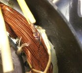
following the diagram from the link on previous post... I needed to identify the start winding and thx to the hints from "lilredex" found one end of the start winding the other end was buried in these heat insulators. pic IMG1..
Checked every heat insulators all have 1 magnetic wire except the yellow confirmed with a continuity tester...... cut wire separate into two, identify which wire go which with the ohm meter. ... mark and add an extra wire.... for the separated start and primary winding.. use mechanical crimp then solder over it... slip back the fiberglass heat insulator. (this would be one end of the start coil) Re-tie everything. nicely back. IMG2 IMG3 IMG4
cut and break the original blue wire that goes to the end of the centrifugal switch. Added a new wire out... this would be the other end of the start coil with the centrifugal switch capacitor.... IMG5
Tuck everything nicely and close cover... IMG6
Verify the coil resistances should have 3 coils.... W1 W2 are the primary running coils.... W3 the start coil...
Test on the test bench.... in my case a fused switch ..
As the plate indicated.... for 110V...
Original configuration...
Connect black Red and new Black wire for Hot , Connect Yellow Grey and new white wire.... for neutral it rotates ..
Connect black red and new white wire for hot, connect yellow grey and new black wire for neutral, now it spins the other way....
Now just waiting for the TPDT center off switch to complete the switched reverse installation. TPDT instead of a DPDT.... is because I wanted to break the Hot wire while it's on Center Off, not to accidentally switch to reverse or start the motor while the start coil is not connected... Any comment on this part is appreciated. More of a safety thing...
It's easier than you think....
Use common sense lots of it...
following the diagram from the link on previous post... I needed to identify the start winding and thx to the hints from "lilredex" found one end of the start winding the other end was buried in these heat insulators. pic IMG1..
Checked every heat insulators all have 1 magnetic wire except the yellow confirmed with a continuity tester...... cut wire separate into two, identify which wire go which with the ohm meter. ... mark and add an extra wire.... for the separated start and primary winding.. use mechanical crimp then solder over it... slip back the fiberglass heat insulator. (this would be one end of the start coil) Re-tie everything. nicely back. IMG2 IMG3 IMG4
cut and break the original blue wire that goes to the end of the centrifugal switch. Added a new wire out... this would be the other end of the start coil with the centrifugal switch capacitor.... IMG5
Tuck everything nicely and close cover... IMG6
Verify the coil resistances should have 3 coils.... W1 W2 are the primary running coils.... W3 the start coil...
Test on the test bench.... in my case a fused switch ..
As the plate indicated.... for 110V...
Original configuration...
Connect black Red and new Black wire for Hot , Connect Yellow Grey and new white wire.... for neutral it rotates ..
Connect black red and new white wire for hot, connect yellow grey and new black wire for neutral, now it spins the other way....
Now just waiting for the TPDT center off switch to complete the switched reverse installation. TPDT instead of a DPDT.... is because I wanted to break the Hot wire while it's on Center Off, not to accidentally switch to reverse or start the motor while the start coil is not connected... Any comment on this part is appreciated. More of a safety thing...
Attachments


Last edited:
finished ..Decided to just use what I have... a DPDT (No Center Off). Original plan of TPDT center off was not needed because the DPDT reverse / forward is only switching the starting coil (the circuit) which will be disconnected by the centrifugal switch once motor is up to speed in forward or reverse...... so having TPDT center off , offered no benefits and complicate things. especially if I am already using the original DP on/off switch. (you will needed a QPDT) if you wanted to combine them into one switch. but that wiring is messy....and tight. I don't trust my wire organizing skills in tight space.
crimped a harness..with 3/16 quick disconnects I think... that is what its called. Longer white / black leads goes to the switched neutral / Hot (the other side of the DP on/off switch.... and will be connected to the two Center pin of the DPDT. The shorter uncrimped black / white wire will go to the two new wire that was extended out from the motor.... the W3 coils....
switched to a 2 gang aluminum weather proof box from a 1 gang (original box housing the switch was broken) . Cut a square on the cover plate to fit original dp on/off switch, drill hole for the DPDT switch.
and everything mounted.
Youtube of the DP in reverse then forward in capture with iphone slo-mo... the spindle actually spins faster and smoother.... it's just the slo-mo video....
Oh well on to the next fun things....
one last thing....
*****This setup is only good for 120V motor setup.... if this was a 220V wiring, 3 new wires needed to bought over from the motor and wiring the DPDT switch will be a little different. Just use a lot of common sense and safety.
Last edited: