To avoid these ads, REGISTER NOW!

Generator, main and subpanel wiring

terabitdan

Well-known member
Joined
Jul 16, 2016
Messages
152
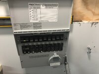
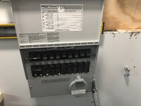
I'm wiring in a generator manual transfer switch into my electrical system the generator panel supports 10 circuits, each with separate transfer switches. The manual transfer panel is installed below the main and a subpanel. The goal is to transfer circuits in either panel. Is that legal?

For each circuit to be transferred both the load and circuit breaker are connected down into the circuits generator panel transfer switch. There is a single ground and neutral from the main to the generator panel.

My plan is to run conduit between the three boxes with some loads from each panel going to the generator panel.

Is this to code or do I need to move all generator circuits to one of the panels?

aac4b2718ad375177c936f7b7456f867.jpg

e76824c335e9a3a233af0574e91e4432.jpg
296bf55d95d2d60dbe4fba082e08f0af.jpg


Sent from my iPhone using Tapatalk
 

Attachments

  • aac4b2718ad375177c936f7b7456f867.jpg
    aac4b2718ad375177c936f7b7456f867.jpg
    810.7 KB · Views: 0
  • e76824c335e9a3a233af0574e91e4432.jpg
    e76824c335e9a3a233af0574e91e4432.jpg
    540.8 KB · Views: 0
  • 296bf55d95d2d60dbe4fba082e08f0af.jpg
    296bf55d95d2d60dbe4fba082e08f0af.jpg
    594.1 KB · Views: 0
To avoid these ads, REGISTER NOW!

wyliesdiesels

Well-known member
Joined
Aug 14, 2012
Messages
20,067
Location
Modesto, CA
I will have to flip through my NEC as Ive never encountered that question before but I have a hunch that all circuits must originate from the same panel....
 

mm08822

Well-known member
Joined
Jan 13, 2012
Messages
6,032
Location
NJ
Electrically it will work, but will not be code compliant as I see it. It would also be a very convoluted installation that I don’t think anyone would have a good comment about.

The code issue:
The existing greenfield from the Pro/Trans needs to be split in two directions to connect to the main panel and the sub panel branch ckts. Doing so requires all conductors of the circuits to be in the same raceway, which then requires a neutral to be run to each panel from the Pro/Trans. The original wiring from the Pro/Trans has only one neutral. Adding a second neutral is easy, but it creates a problem of parallel paths in the neutral of the feeder between the main and sub panel.

If you try to eliminate the parallel neutral path by running everything through the main panel and terminating only one neutral at the main panel neutral bar, then the ckt conductors from the Pro/Trans have to go through the sub panel feeder conduit. This creates fill issues and derating issues in that conduit. Also the main panel is now being used as a pull box.

Ever thought about a larger sub panel? You could re-use all breakers and just buy a larger main lug panel. This would give you room to move whichever romex circuits from the main panel to the sub panel that you want backed up and have leftover space. Have the Pro/Trans connect up only to the sub panel.
Your main panel would also free up a few ckts doing this.
 

theoldwizard1

Well-known member
Joined
Feb 22, 2011
Messages
43,243
Location
SE MI
Usually.

However, in the OPs case his panel is maxed out and would need to move several circuits that are right next to the main, to be able to do an interlock.
Actually, there is 1 slot at the bottom left.

I noticed that, but a small add on load center with about 20 circuits would als be a quick and easy add.
 
Last edited:
OP
T

terabitdan

Well-known member
Joined
Jul 16, 2016
Messages
152
Thanks for the responses, I was concerned about how a single neutral wire would be up to code. The neutral is only connected to the generator input in the gen panel.

There are far more spaces open than you see, I have 3 open dual slots and 3 unused breakers, meaning adding up to 9 circuits into the main is possible.

The sub-panel is new, I'm moving a sub panel from the furnace room since it's in a shelving unit and to use the generator for some of the circuits. My plan was to bring everything into the main panel, after some circuit consolidation there would have been 2 open slots for a future sub-panel if it was ever needed.

Then the company installing a new mini-split for the garage to room conversion said they could not tie it into the interruptible service, taking the last remaining space. That's why there is a new sub-panel.

With a little work, I can move all the generator protected circuits to one panel. Or bring conduit from both sides of the gen panel, one to either panel.

That's when I decided to ask the experts on GJ! Make sure it's done right the first time.


Sent from my iPhone using Tapatalk
 
OP
T

terabitdan

Well-known member
Joined
Jul 16, 2016
Messages
152
One additional question, are GFCI breakers required for the gen panel? If so, wouldn't I need to bring the neutral into the gen panel for any of those circuits?


Sent from my iPhone using Tapatalk
 

mm08822

Well-known member
Joined
Jan 13, 2012
Messages
6,032
Location
NJ
Thanks for the responses, I was concerned about how a single neutral wire would be up to code. The neutral is only connected to the generator input in the gen panel.

In the instructions I looked at, there is a neutral and grd wire that has to be run between the Trans/Pro panel and the house panel. I think you are only referring to the wire between the generator and the power inlet of the Trans/Pro. Still need to get to the house panel neutral bar.

The branch cb in the main panel feeds the house circuit when the selector switch is in “Line” position and the generator feeds the house ckt from the cb in the Trans/Pro when the selector switch is in “Gen” position. The neutral of the ckt remains connected to the house neutral bar.

Below is the info I found on mfr website.
Trans_Pro.jpg
 

mm08822

Well-known member
Joined
Jan 13, 2012
Messages
6,032
Location
NJ
One additional question, are GFCI breakers required for the gen panel? If so, wouldn't I need to bring the neutral into the gen panel for any of those circuits?


Sent from my iPhone using Tapatalk

If the ckt is required to have gfci protection, then is should also have it when running on the gen. However, now you need that individual neutral run to the gfci cb in the Trans/Pro while it is still connected to the house panel gfci cb. This getting very messy and I dont know if either gfci will detect any leakage due to the other gfci hanging on the neutral.
 
OP
T

terabitdan

Well-known member
Joined
Jul 16, 2016
Messages
152
In the instructions I looked at, there is a neutral and grd wire that has to be run between the Trans/Pro panel and the house panel. I think you are only referring to the wire between the generator and the power inlet of the Trans/Pro. Still need to get to the house panel neutral bar.


The branch cb in the main panel feeds the house circuit when the selector switch is in “Line” position and the generator feeds the house ckt from the cb in the Trans/Pro when the selector switch is in “Gen” position. The neutral of the ckt remains connected to the house neutral bar.


Below is the info I found on mfr website.

Trans_Pro.jpg


Yes, that's what I was saying, but not very clearly. There is not a neutral bar in the gen panel, nor is the neutral switched.

The strange thing is, if I did use a generator interlock then feeding circuits from multiple panels isn't an issue, but I like individually switching circuits, and that when power returns all the other circuits come up.

Seems like it's best to put all gen circuits in one panel.


Sent from my iPhone using Tapatalk
 
OP
T

terabitdan

Well-known member
Joined
Jul 16, 2016
Messages
152
If the ckt is required to have gfci protection, then is should also have it when running on the gen. However, now you need that individual neutral run to the gfci cb in the Trans/Pro while it is still connected to the house panel gfci cb. This getting very messy and I dont know if either gfci will detect any leakage due to the other gfci hanging on the neutral.


So I could install a GFCI breaker in the feed to the panel to protect all the circuits simultaneously, right?


Sent from my iPhone using Tapatalk
 
To avoid these ads, REGISTER NOW!
OP
T

terabitdan

Well-known member
Joined
Jul 16, 2016
Messages
152
What feed?


Each circuit has a feed.


There is no main feed.


From the generator to the generator panel. So generator connects to the receptacle outside. Install a box with single 240v GFCI breaker in the line from the receptacle to the generator panel, providing GFCI protection for all loads on the generator.

Who knows, there might be a GFCI protection on the generator already, I'll check tonight. But I could see an inspector requiring one to be permanently installed.


Sent from my iPhone using Tapatalk
 

wyliesdiesels

Well-known member
Joined
Aug 14, 2012
Messages
20,067
Location
Modesto, CA
Youre making this way more complicated than it has to be.

Have you ever thought of doing an interlock instead?

Just have to move the 2 breakers right next to the main. Means moving 2 circuits.

Lot less work than wiring a gen tran panel between 2 panels or even one.
 

Radix2

Well-known member
Joined
May 28, 2014
Messages
1,853
Location
the thumb!, MI
Couple questions.

What are you trying to accomplish with this switch box over a interlock? Seems to me the only "advantage " is the ability to run the gen in parralel with mains power...how this is useful I do not know. Aditionally it makes it clear which circuits can be run from the gen...but this seems to be a disadvantage since you can accomplish the same with some Lables an it absolutely prevents any other circuits from being powered from the gen...and it is expensive...

Electrically there must be a requirement to size the ground and neutral for the full capacity if the generator. Given this is done I don't see any electrical issue caused by running circuits from multiple panels (neutral to each) . I don't follow 8822s code issue noted above, but maybe there is one..

I actually have a similar issue, just did interlocks in both panels. Simple and gives complete capability to run any circuit from the gen if desired.
 

theoldwizard1

Well-known member
Joined
Feb 22, 2011
Messages
43,243
Location
SE MI
Youre making this way more complicated than it has to be.

Have you ever thought of doing an interlock instead?
Hmmm .... Where have I heard this before !

Only down side (?) to using an interlock in this application is being smart enough to turn off those big 240V loads.
 

mm08822

Well-known member
Joined
Jan 13, 2012
Messages
6,032
Location
NJ
Hmmm .... Where have I heard this before !

Only down side (?) to using an interlock in this application is being smart enough to turn off those big 240V loads.

Agreed, but OP already had the transfer panel purchased/halfway installed. So you try to work with that. Except this hole just kept getting deeper, so it was time to bail on this approach.

And all loads should be initially turned off so you can slowly load gen with only the important stuff or time-share as required.
 
OP
T

terabitdan

Well-known member
Joined
Jul 16, 2016
Messages
152
Youre making this way more complicated than it has to be.

Have you ever thought of doing an interlock instead?

Just have to move the 2 breakers right next to the main. Means moving 2 circuits.

Lot less work than wiring a gen tran panel between 2 panels or even one.


LOL, so on the drive home this occurred to me, fuggetabout that darn gen panel and just buy an interlock kit. So I did thinking planning to install it in the sub panel. But you are right, better to just put it in the main and then any panel circuit can be used. I guess the only downside is having to shut off all the unused breakers.

Thanks!

Anyone want a manual transfer panel?

Radix, thanks for your input also. I could move the gen panel to the garage sub, and use my small generators for that if the needed.

Sent from my iPhone using Tapatalk
 
Last edited:

yeldogt

Well-known member
Joined
Jan 2, 2012
Messages
18,184
Do the same rules apply for manual as auto -- we can't have a generator connected that's not sized correctly. Obviously, this generator can't run the whole house .... if it was an auto switch they would not allow.

I don't understand the OP's problem -- why not use a typical supplemental generator sub-panel as intended? easy and no issues.
 

wyliesdiesels

Well-known member
Joined
Aug 14, 2012
Messages
20,067
Location
Modesto, CA
Do the same rules apply for manual as auto -- we can't have a generator connected that's not sized correctly. Obviously, this generator can't run the whole house .... if it was an auto switch they would not allow.

I don't understand the OP's problem -- why not use a typical supplemental generator sub-panel as intended? easy and no issues.

No

Generator with manual transfer switch or interlock is not required to be sized for entire load or have load shedding capability.
 
Last edited:

yeldogt

Well-known member
Joined
Jan 2, 2012
Messages
18,184
Those two item drive the cost of a whole house system up A LOT !!

Well they force you to match the generator to the load ....

I still don;t understand why the OP can't just use the generator panel he has -- pulled out the circuits he want to run and connect to the dedicated panel.
 

arkieguide

Well-known member
Joined
Aug 10, 2017
Messages
50
I will have to think about this some more to give an educated answer.At first I though stay away from this type installation. But it can work, but be pretty involved for an electrician shooting trouble, take him a few minutes to get it in his head.I keep trying to put an auto transfer switch on a separate panel with only the needed circuits thru it.But have to think some more.Good luck.
 
To avoid these ads, REGISTER NOW!
Top Bottom