To avoid these ads, REGISTER NOW!

Plow Build #2

f150skidoo

Well-known member
Joined
Dec 29, 2012
Messages
1,206
Location
Ontario, Canada
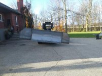
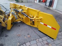
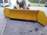
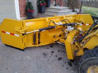
Well I'm back at it doing another build thread, I got a new site this year It's a town house HOA. My pusher that I built last year will do the job but won't be very efficient and we all know time is $$$$$. The blade I want is a 6 way wing blade, So its a regular angle blade but with hydraulic wings that actuate 180 degrees. Link to a example. http://hlasnow.com/snowwing.php

I was looking at buying one of these blades but a small one for my skid steer would cost $10k new and used are still $7-8K. So I decided to just build one.

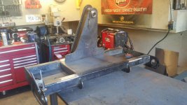
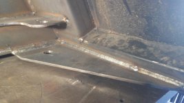
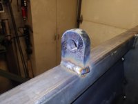
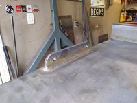
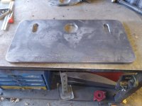
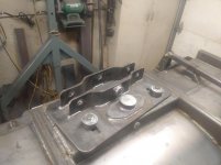
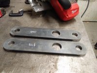
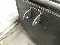
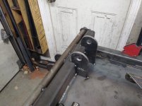
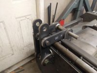
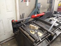
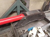
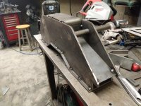
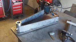
I started working on it a few weeks back, I had a extra quick attach plate laying around that I used and I fabricated the A frame and cylinder mounts out of 1/4" plate. The main pivot pin will be 1.25" and the angling cylinders will be two 2.5"x 6" cylinders
 

Attachments

  • 20170924_162947.jpg
    20170924_162947.jpg
    143.7 KB · Views: 461
  • 20170924_173059.jpg
    20170924_173059.jpg
    145.9 KB · Views: 453
  • 20170925_161826.jpg
    20170925_161826.jpg
    139.4 KB · Views: 401
  • 20171001_104559.jpg
    20171001_104559.jpg
    139.8 KB · Views: 460
  • 20171001_140925.jpg
    20171001_140925.jpg
    143.2 KB · Views: 402
  • 20171001_141005.jpg
    20171001_141005.jpg
    138.3 KB · Views: 425
To avoid these ads, REGISTER NOW!
OP
F

f150skidoo

Well-known member
Joined
Dec 29, 2012
Messages
1,206
Location
Ontario, Canada
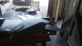
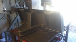
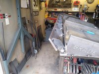
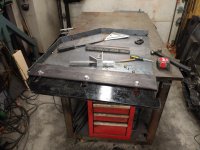
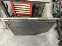
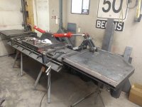
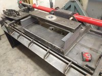
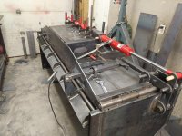
So the main mold board will be 7' and each wing is 30" so this blade fully opened up will be 12'. The moldboard frame is 2"x6" .188" tube and I plasma cut the curve into the tube. The upper tube is 2"x2" .188" tube and the lower angle is 2"x3" 3/8". The skin of the blade is 11 ga. (1/8"), I placed the entire blade in my press and used what ever tube and angle I had laying around so I could press the skin into the shape of the frame.
 

Attachments

  • 20171014_155803.jpg
    20171014_155803.jpg
    142.8 KB · Views: 420
  • 20171011_171017.jpg
    20171011_171017.jpg
    133.5 KB · Views: 328
  • 20171011_171005.jpg
    20171011_171005.jpg
    137.1 KB · Views: 370

bullnerd

Well-known member
Joined
Sep 17, 2012
Messages
5,690
Location
Jersey
Well its about time! NO more making us wait for a week or two before the next Fab thread!

LOL!

Did you plasma all the flat stock for the A-frame? (curvy parts)

How's the Lincoln holding up?
 
OP
F

f150skidoo

Well-known member
Joined
Dec 29, 2012
Messages
1,206
Location
Ontario, Canada
Made a bunch of progress today. Since I skinned the frame yesterday I had nothing to hook my chains up too for lifting the blade with my over head hoist. I made a lifting eye out of some scrap 3/4" plate, next I welded out the 1/8" skin to the frame. The next step was to tackle the trip edge mechanism, I used some 3/8"x1.5" flat bar for the springs to mount. For the tripping edge I used 1" cold rolled round for the pin, 1/4"x2" for the brackets, and 1/2"x4" for the mount for the bolt on cutting edge.
.
 

Attachments

  • 20171015_073157.jpg
    20171015_073157.jpg
    124.7 KB · Views: 322
  • 20171015_155218.jpg
    20171015_155218.jpg
    136.8 KB · Views: 304
  • 20171015_152254.jpg
    20171015_152254.jpg
    147.6 KB · Views: 338
  • 20171015_154432.jpg
    20171015_154432.jpg
    143.2 KB · Views: 326
  • 20171015_154406.jpg
    20171015_154406.jpg
    144.4 KB · Views: 334
OP
F

f150skidoo

Well-known member
Joined
Dec 29, 2012
Messages
1,206
Location
Ontario, Canada
Wait, there's a plow build #1?!

Looking good so far!

Thanks it's in my signature called pusher box build


Well its about time! NO more making us wait for a week or two before the next Fab thread!

LOL!

Did you plasma all the flat stock for the A-frame? (curvy parts)

How's the Lincoln holding up?

Yes I plasma cut all the curvy **** and my Lincoln has been flawless since the hick up with the power switch issue last year.
 

Bighead38

Well-known member
Joined
Nov 11, 2012
Messages
5,612
Location
Rockland County NY
You obviously know what to do and how to do it. You can obviously make a top notch product. Ever considered making products to sell or going into business? Doesn’t have to be full time but I bet you could get a premium price for your products.
 
OP
F

f150skidoo

Well-known member
Joined
Dec 29, 2012
Messages
1,206
Location
Ontario, Canada
You obviously know what to do and how to do it. You can obviously make a top notch product. Ever considered making products to sell or going into business? Doesn’t have to be full time but I bet you could get a premium price for your products.

This year I've actually built a ton of stuff for people but I'm not ready yet to do this full time, maybe in a few years.
 
OP
F

f150skidoo

Well-known member
Joined
Dec 29, 2012
Messages
1,206
Location
Ontario, Canada
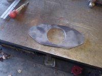
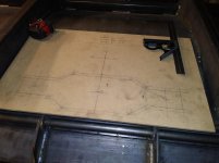
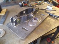
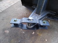
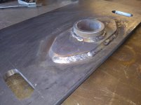
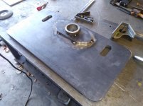
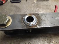
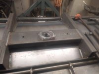
So I had a pretty good weekend of doing Fab work, So these posts will be pretty picture heavy. The first thing to do was finish building the trip edge mechanisms then weld out all those parts. The next part of the build was probably the most difficult to design/ build. This part is what connects the angling cylinders and A frame to the moldboard but will also allow the blade to laterally float independently to the machine. I spent a lot of time laying out the design on a chunk of MDF before I transferred everything to steel. The rod end of the cylinders were a lot shorter then the main pivot point so I bent up some 3.5"x3/8" flat bar to compensate for the differences in heights. The plate I'm using in this part is 12" x1/2" plate 24" long. The pivoting portion for the lateral float is 3" x5/16" wall DOM and will rotate on a 2 3/8" pin. I machined two slots in the 1/2" plate for bolts that will limit the movement of the float.
 

Attachments

  • 20171022_144716.jpg
    20171022_144716.jpg
    142 KB · Views: 191
  • 20171022_155111.jpg
    20171022_155111.jpg
    139.8 KB · Views: 200
  • 20171022_144650.jpg
    20171022_144650.jpg
    145.9 KB · Views: 205
  • 20171021_191003.jpg
    20171021_191003.jpg
    126.4 KB · Views: 204
  • 20171021_190911.jpg
    20171021_190911.jpg
    138.2 KB · Views: 198
  • 20171021_150139.jpg
    20171021_150139.jpg
    142.2 KB · Views: 221
OP
F

f150skidoo

Well-known member
Joined
Dec 29, 2012
Messages
1,206
Location
Ontario, Canada
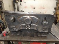
Next I tacked up the plate stiffener around the DOM then welded it to the main 1/2" plate. Before I welded on the cylinder/A frame mounts I did a quick test fit then welded it on the 1/2" plate. After getting those parts welded up I bolted the cylinders on and tested the range of motion.
 

Attachments

  • 20171022_180400.jpg
    20171022_180400.jpg
    141.4 KB · Views: 280
  • 20171022_180255.jpg
    20171022_180255.jpg
    144.9 KB · Views: 296
  • 20171022_180215.jpg
    20171022_180215.jpg
    143.3 KB · Views: 311
  • 20171022_174643.jpg
    20171022_174643.jpg
    145.5 KB · Views: 223
  • 20171022_172445.jpg
    20171022_172445.jpg
    147.7 KB · Views: 232
  • 20171022_162354.jpg
    20171022_162354.jpg
    143 KB · Views: 220
  • 20171022_161023.jpg
    20171022_161023.jpg
    142.9 KB · Views: 229
OP
F

f150skidoo

Well-known member
Joined
Dec 29, 2012
Messages
1,206
Location
Ontario, Canada
Some progress from today, I finished making all the parts for the lateral float. The main pivot pin is 2.375" cold rolled round bar and I welded on a slug of 1/2" plate from a hole saw as a part of the retaining system, then I drilled the pin for grease passages. I made some dogs that are held down with 5/8" bolts that will limit the lateral float. I used some left over 2"x6" .188" tube for the plow side of the float system and welded in the 3" DOM and drilled the 5/8" bolt holes for the float limiters. I welded nuts on the back side of the 2"x6" tube for the 5/8" holes and the 3" DOM also has a nut welded on the bottom for 5/8" bolt as the pin retainer. After welding the 2"x6" tube to the plows frame I cut and bent some 3/16" plate for to strengthen and cover up the bottom of the middle section. With the amount of movement in the float system I calculated that the blade will have 15" of movement when the blade is opened up to 12'.
 

Attachments

  • 20171028_194346.jpg
    20171028_194346.jpg
    130.9 KB · Views: 173
  • 20171028_192818.jpg
    20171028_192818.jpg
    126.4 KB · Views: 164
  • 20171028_192806.jpg
    20171028_192806.jpg
    127.3 KB · Views: 170
  • 20171028_141339.jpg
    20171028_141339.jpg
    127.8 KB · Views: 172
  • 20171028_115907.jpg
    20171028_115907.jpg
    139.4 KB · Views: 209
  • 20171028_115335.jpg
    20171028_115335.jpg
    144.9 KB · Views: 167
  • 20171028_115356.jpg
    20171028_115356.jpg
    145.4 KB · Views: 179
OP
F

f150skidoo

Well-known member
Joined
Dec 29, 2012
Messages
1,206
Location
Ontario, Canada
Toady I fabricated the plows wings. The cutting edges for the wings are a from another brand of wing plow that i'm using on my blade for ease of replacement once the edges wear out. The cutting edges will float independently from the main moldboard and will move between two pieces of 3/8"x5" flat bar. The wings consist of two pieces 3/16" plate, 1/4"x2.5" flat bent to the wings contour and 1.5" square tube .
 

Attachments

  • 20171029_175548.jpg
    20171029_175548.jpg
    137.5 KB · Views: 176
  • 20171029_150326.jpg
    20171029_150326.jpg
    137.3 KB · Views: 161
  • 20171029_132212.jpg
    20171029_132212.jpg
    136.9 KB · Views: 159
  • 20171029_120040.jpg
    20171029_120040.jpg
    135.7 KB · Views: 157
  • 20171029_120136.jpg
    20171029_120136.jpg
    135.2 KB · Views: 155
  • 20171029_082127.jpg
    20171029_082127.jpg
    145.6 KB · Views: 158
OP
F

f150skidoo

Well-known member
Joined
Dec 29, 2012
Messages
1,206
Location
Ontario, Canada
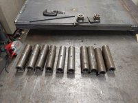
Since today was a rain day I was able to do a bunch of running around picking up parts I needed for the blade. Luckily I was able to squeeze in a few hours to do some fabricating. The hinges for wings are just like a piano hinge but my hinges are 1.5" DOM tubing with a 1" 1018 CR pin. I added some 3/8" flat bar to the DOM so the grease zerks won't come in contact with the 2"x6" tube. Now with the wings on the blade its maximum width is 150" (12' 6").
 

Attachments

  • 20171102_153950.jpg
    20171102_153950.jpg
    132.9 KB · Views: 192
  • 20171102_144128.jpg
    20171102_144128.jpg
    140.9 KB · Views: 163
  • 20171102_094112.jpg
    20171102_094112.jpg
    126.2 KB · Views: 156
  • 20171031_194849.jpg
    20171031_194849.jpg
    144.7 KB · Views: 150
OP
F

f150skidoo

Well-known member
Joined
Dec 29, 2012
Messages
1,206
Location
Ontario, Canada
I had to assemble the blade and Q/A part so I could check my measurements for clearance between the Q/A frame and what will be the wings cylinder & mounts.

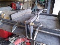
Trying to make these wings rotate with a normal cylinder was the hardest thing I've ever designed. Before I made anything in steel I used wood and hot glued it to the steel and changed the design as I went until I was happy with the range of motion. Next was to make all the parts out of steel. The mounts on the wing and mold board are 3/8" plate and the moving parts are 1/2"x2.5" flat with 1.5"x.250" wall DOM.
 

Attachments

  • 20171105_070340.jpg
    20171105_070340.jpg
    142.9 KB · Views: 198
  • 20171105_064311.jpg
    20171105_064311.jpg
    145 KB · Views: 196
  • 20171105_062426.jpg
    20171105_062426.jpg
    121.8 KB · Views: 214
  • 20171103_160859.jpg
    20171103_160859.jpg
    147.6 KB · Views: 278
  • 20171103_160841.jpg
    20171103_160841.jpg
    143 KB · Views: 255
  • 20171103_160412.jpg
    20171103_160412.jpg
    144.2 KB · Views: 242
Last edited:
OP
F

f150skidoo

Well-known member
Joined
Dec 29, 2012
Messages
1,206
Location
Ontario, Canada
Some more pics. The design of the mounts are similar to how a excavator curls its bucket.
 

Attachments

  • 20171105_070826.jpg
    20171105_070826.jpg
    137.1 KB · Views: 137
  • 20171105_081520.jpg
    20171105_081520.jpg
    145.2 KB · Views: 152
  • 20171105_091851.jpg
    20171105_091851.jpg
    136.4 KB · Views: 133
  • 20171105_092510.jpg
    20171105_092510.jpg
    128.6 KB · Views: 144
OP
F

f150skidoo

Well-known member
Joined
Dec 29, 2012
Messages
1,206
Location
Ontario, Canada
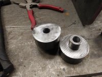
The cylinder that I'm using has a 2.5" bore and 16" of stroke. The mount for the gland end of both wing cylinders is 1/4" plate. When I was using my wooden templates for testing the motion of the wings I discovered to get a full 180 degrees I would need to get custom cylinders made up$$$$$. No matter what I did to the wings mounts/push rods I could not get it to work with standard sized cylinders. So I opted to sacrifice the wings motion to be able to use a normal cylinder, I was able to get 162 degrees of movement.
 

Attachments

  • 20171105_190131.jpg
    20171105_190131.jpg
    136.5 KB · Views: 205
  • 20171105_185914.jpg
    20171105_185914.jpg
    142 KB · Views: 180
  • 20171105_185725.jpg
    20171105_185725.jpg
    138 KB · Views: 165
  • 20171105_184559.jpg
    20171105_184559.jpg
    145.2 KB · Views: 159
To avoid these ads, REGISTER NOW!

texasranger

Well-known member
Joined
Dec 29, 2011
Messages
223
Location
Maryland
Impressive work. My only comment is the attachment point on the wing is awfully close to the hinge. I'd be a little scared of catching something with the edge of the wing and bending it, unless you're only planning to run in box mode. Are you going to add a cushioning valve as a precaution?
 

tarbellb

Well-known member
Joined
Apr 17, 2011
Messages
5,770
Location
Oregon
Wow! Lots of thought and fab skill going on, well done.

How much would you guess its going to weigh?
 
OP
F

f150skidoo

Well-known member
Joined
Dec 29, 2012
Messages
1,206
Location
Ontario, Canada
Impressive work. My only comment is the attachment point on the wing is awfully close to the hinge. I'd be a little scared of catching something with the edge of the wing and bending it, unless you're only planning to run in box mode. Are you going to add a cushioning valve as a precaution?
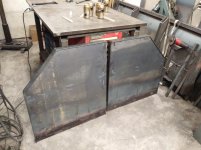
Im running crossover relief valves on each of the blades hydraulic circuits so if i catch anything the cylinders will bypass before anything gets bent.
Sent from my LG-M320G using Tapatalk
 
OP
F

f150skidoo

Well-known member
Joined
Dec 29, 2012
Messages
1,206
Location
Ontario, Canada
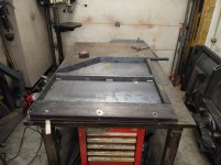
I picked up the single most expensive part of the blade on Saturday, the electric diverter valve. I could of done something cheaper to control all the hydraulic functions but it wouldn't be as good as this diverter valve. With a flick of a switch on the joystick I can control all the blades movements on the fly while plowing. This weekend's progress wasn't very good, I fabricated the other wings push rods and then started to weld out all the parts. I then stopped for a quick beer break and while I was admiring my handy work I realized a design flaw. I figured on a project this complicated being built with no plans their would be some design issues/changes, but this was a major design oversight. The problem is when the wing cylinders are in the reverse box blade position all the way up to the wings being parallel with the mold board the quick attach plate hits the wings cylinders. To be on the safe side I figure that I need a extra 6" of clearance. To gain the extra clearance some of the options I thought of was completely redesign the wings cylinder mounts/ push rods, or rebuild the quick attach plate/ A frame. Both of those options would be A lot of work to do, So the option that I'm going to use is build out the center section where the 1/2" plate pivoting part mounts to the blade. This way to fix the problem has the least amount of cutting welds :beer: and is the easiest build and also the cheapest option. Ill just have to make sure that it looks like it was by design and not a mistake.
 

Attachments

  • 20171112_171801.jpg
    20171112_171801.jpg
    129.4 KB · Views: 231
  • 20171112_122930.jpg
    20171112_122930.jpg
    136.8 KB · Views: 200
  • 20171112_122248.jpg
    20171112_122248.jpg
    133.8 KB · Views: 219
  • 20171112_112844.jpg
    20171112_112844.jpg
    135.1 KB · Views: 208
  • 20171111_091643.jpg
    20171111_091643.jpg
    143.4 KB · Views: 202
Last edited:
OP
F

f150skidoo

Well-known member
Joined
Dec 29, 2012
Messages
1,206
Location
Ontario, Canada
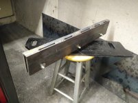
So I did'nt take many pictures but I got the clearance issue resolved. I actually only needed 4" of clearance but I made it 7" to be safe. I made the plow pivot mount the same as the original but I used some left over 5" channel to space the tube off of the frame. Next I used 1/4" plate to box in the new pivot mount and used a longer piece to strengthen the bottom of the plow and to help the repair to look like it was buy design. I then finished up welding out all the remaining joints and finishing up all the odds and ends on the blade. I have a few hours of work on the Q/A-A frame to finish up all the odds and ends then just paint.
 

Attachments

  • 20171118_114133.jpg
    20171118_114133.jpg
    142.5 KB · Views: 168
  • 20171118_180755.jpg
    20171118_180755.jpg
    144 KB · Views: 163
  • 20171119_171540.jpg
    20171119_171540.jpg
    135.7 KB · Views: 174

Bretny

Well-known member
Joined
Jul 31, 2017
Messages
3,918
Location
Dutchess county NY
Wonderfull work you do.
I was a former diesel tech for a fleet of state operated plow trucks.
I would add some more hinge material to the trip edge and bottom of the plow face. Thats a place that takes alot of load and many hits.
 
OP
F

f150skidoo

Well-known member
Joined
Dec 29, 2012
Messages
1,206
Location
Ontario, Canada
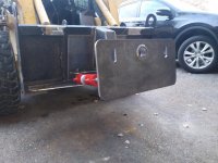
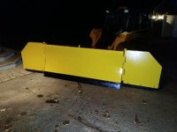
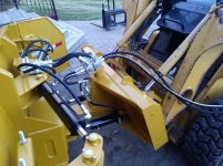
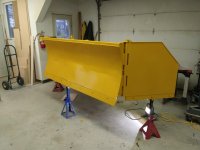
So on the weekend the blade got all painted up then assembled, Today I got all the hydraulic lines made up and plumbed up, and the electric diverter valve wired up also. The blade is now fully operational and working well. I have only 2 things that still need to do, 2 hoses are just a little bit to short for my liking and the drive in grease fittings are blowing out of the holes so i'm going to replace them with thread in fittings. Ill take some better pictures tomorrow when theirs day light.
 

Attachments

  • 20171127_192949.jpg
    20171127_192949.jpg
    146.9 KB · Views: 210
  • 20171127_192845.jpg
    20171127_192845.jpg
    138.9 KB · Views: 218
  • 20171127_160453.jpg
    20171127_160453.jpg
    140.3 KB · Views: 229
  • 20171127_160444.jpg
    20171127_160444.jpg
    144.3 KB · Views: 239
  • 20171125_154409.jpg
    20171125_154409.jpg
    123.6 KB · Views: 226
Last edited:
OP
F

f150skidoo

Well-known member
Joined
Dec 29, 2012
Messages
1,206
Location
Ontario, Canada
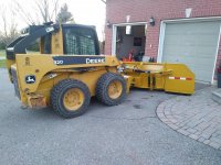
Here is some more pictures taken in the daylight. I also recorded a video of it in action but I have to figure out how do some editing so I can delete the 40 seconds of me accidentally recording my legs. LOL
 

Attachments

  • 20171128_163301.jpg
    20171128_163301.jpg
    148.8 KB · Views: 216
  • 20171128_163426.jpg
    20171128_163426.jpg
    146.1 KB · Views: 211
  • 20171128_163510.jpg
    20171128_163510.jpg
    146.4 KB · Views: 224
  • 20171128_164210.jpg
    20171128_164210.jpg
    142.4 KB · Views: 210
  • 20171128_164225.jpg
    20171128_164225.jpg
    146.6 KB · Views: 219

tlmartin84

Well-known member
Joined
Apr 23, 2012
Messages
1,085
Location
West Virginia
Awesome, when something looks like it is factory you have really accomplished something!

Did you cut all of your steel plate with the Milwaukee?
 

WhiffySpark

Well-known member
Joined
Oct 22, 2009
Messages
6,252
Incredible work. How much do you have into it? We run all regular box’s but no hoa and not interested in them lol.

We run all rubber edges. Even trucks are rubber now
 

bigguns69

Well-known member
Joined
Aug 23, 2011
Messages
411
Location
Iowa
If you aren't doing this full time, maybe you should consider. Excellent, creative work.
 
To avoid these ads, REGISTER NOW!
Top Bottom