To avoid these ads, REGISTER NOW!

Sizing a gas line

FreddiFiche

Well-known member
Joined
Aug 8, 2011
Messages
126
Location
Minnesnowta
I found a online calculator, that lets me model my hybrid gas system, but I see there are a few guys that are way smarter than I lurking around here....And i wanted some second opinions, since I don't want to pull a line to only have the final installer tell me it is too small.

I plan on using Csst for the new run (part in the pink circle), but after i see my city requirements for inspection, I came to the conclusion that having a pro do the final hook-up and pressure testing is in order. Will undoubtedly same me $$ in the long run.

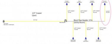
I actually ran around to all the appliances, so these are all the actual input BTU's for the appliances, not estimated. The line lengths are all estimated slightly long to make sure I'm covered. The only thing being added is the furnace (Garage) on the end.

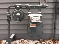
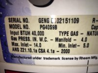
Note: the existing gas systems is 1/2" OD Copper for the 2psi side the .5psi side. The blackpipe manifold is built out of 3/4" Black pipe, and is about 2 feet long.

Diagram of system attached.


Questions:

1) Would the new line be added to the .5 psi side like shown on the diagram, or would it be better to add it to the 2psi side, and use a regulator at the garage furnace? The calculator seems to think that leaving it on the .5 PSI, I can till run my load with a 1/2" CSST. I wouldn't run smaller CSST, but would that give more margin for error?

2) Does anyone have a better calculator that tells me that this is good to go? I'm always leery of a answer without a check.

3) How do i figure out if my gas meter is capable of actually supplying the total load? Whats the margin factor? do you have to assume literally that ALL appliances are running at the same time?

Thanks guys!
 

Attachments

  • Gas System edited.jpg
    Gas System edited.jpg
    11.7 KB · Views: 55
Last edited:
To avoid these ads, REGISTER NOW!

eddieK

Well-known member
Joined
Mar 2, 2017
Messages
695
Location
Nampa Idaho
Not sure about what a hybrid means...40 yrs never heard of it. Also in my neck of the woods Copper is a no no. The smell additive in my area (Southern Cal) eats away copper. I also only know WC when it comes to gas line pressure, as in 6 to 10 Inches of water column to devices and 14 for propane.
 
Last edited:
OP
F

FreddiFiche

Well-known member
Joined
Aug 8, 2011
Messages
126
Location
Minnesnowta
Not sure about what a hybrid means...40 yrs never heard of it. Also in my neck of the woods Copper is a no no. The smell additive in my area (Southern Cal) eats away copper. I also only know WC when it comes to gas line pressure, as in 6 to 10 Inches of water column to devices and 14 for propane.


Thanks for jumping in! I appreciate it.

Hybrid means it a dual pressure system. It's 2PSI from the meter, and they run that too a more convenient spot, and then regulate it down to a .5 PSI system. In my case they did that in the Furnace room. Usually to make the majority of the run smaller line. From there they branch of to the lions share of the appliances, just using the one regulator, so they don't need one on every appliance. I'm allowed to use either side, but obviously need to put a regulator on the end of the line, if i do that to run to the new furnace in the garage.

I would bet that anything over 5 years old, and less than 20 years old, 95% of residential natural gas is soft copper in MN. Before that was a lot of black pipe, and anything newer is CSST. None the less, all of my existing house is copper. Makes me wonder is there are different 'contaminates' in different parts of the country, or just different building codes because the smart guys got involved. I've seen a lot of silly electrical rules around Chicago, because someone was protecting their turf. :)

I don't want to run soft copper, because it is a pain in the ****, when doing multiple bends through walls. Code here allows Black, soft copper, or CSST.

I am going to have a pro come in to do final hook-up and pressure testing, but know having them run the line is going to be expensive. I want to do that myself to make this a bit more reasonably costed.

Only the last load on the diagram is new...all the others are existing.

Does that make more sense?
 

HoosierBuddy

Well-known member
Joined
May 9, 2006
Messages
2,925
Location
Southern Indiana
The problem I see with your plan is that CSST can only be installed by a qualified person who has been trained according to the manufacturer. So, I'm struggling to see how you are going to do the installation and leave the final hookup and testing to the "pro".

Are you saying you are only going to string the CSST yourself in a single run with no fittings and you are going to have the "pro" do the rest including running the required bond wire back to your main electrical panel? If so that might work, I guess.

Then...I'm looking at your diagram...and I admit I can't read a lot of it...but you're saying that you have 1/2 PSI running to your furnace, etc...which is 14 inches water column or about double what I'm used to seeing...so I gotta ask...why do you think you have 1/2 PSI? Did you check that with a manometer?

I realize I'm just being a curmudgeon here. Sorry.

BTW The flow number your looking for will be in your CSST manufacture's procedure manual. The right way to do this, if you want to DIY, is download a copy of the manual, study and understand it prior to beginning the job. Pay special attention to the bonding requirement and if you can't do what is required, don't run CSST. And as I say, once you understand that manual the flow question will answer itself. Also verify your pressure. I'd suggest, unless you live at altitude, the pressure is likely close to 7 inches w/c after your regulator.

Phil
 
Last edited:
OP
F

FreddiFiche

Well-known member
Joined
Aug 8, 2011
Messages
126
Location
Minnesnowta
Are you saying you are only going to string the CSST yourself in a single run with no fittings and you are going to have the "pro" do the rest including running the required bond wire back to your main electrical panel? If so that might work, I guess.

Exactly. The Furnace room is two rooms away from the garage, and requires removing about one sheet for the firewall, in order to run it. I plan to run it through the floor joists, remove the rock, and then replace the rock. I will also run the dedicated 15A run for it at the same time. (Additionally, it will be much easier to pull the 4 - conductor for the new thermostat while that rock is off. You already helped me from doing something twice...didn't know I should pull a extra wire in addition to the NM-b to ground the far end of the CSST. 12g Bare or Green appropriate? (Just separate from the 14-2 i will pull out there?)

Then...I'm looking at your diagram...and I admit I can't read a lot of it...but you're saying that you have 1/2 PSI running to your furnace, etc...which is 14 inches water column or about double what I'm used to seeing...so I gotta ask...why do you think you have 1/2 PSI? Did you check that with a manometer?

No manometers in my future. :) The HVAC guy i called said that if i had the loose CSST, with a couple of extra feet on each end, dedicated power circuit, and the unit hung in place, he would take it from there. I plan to run the thermostat wire, just so the thermostat can be farther away from the new heater. The reason i asked the specific question about which side the CSST should go is to figure out if I should be buying a regulator for the furnace side. The CSST calculator says it CAN go on the .5 PSI side, but my gut tells me keeping it on the 2PSI side make it less likely that i will starve the other appliances.


I realize I'm just being a curmudgeon here. Sorry.

I didn't take it that way at all. Just trying to keep me from killing myself. I'm just trying to make sure i don't have a surprise bill when he gets here. :)


I'll attach a picture of what i have in the furnace room, and see if that helps.


BTW The flow number your looking for will be in your CSST manufacture's procedure manual. The right way to do this, if you want to DIY, is download a copy of the manual, study and understand it prior to beginning the job. Pay special attention to the bonding requirement and if you can't do what is required, don't run CSST. And as I say, once you understand that manual the flow question will answer itself. Also verify your pressure. I'd suggest, unless you live at altitude, the pressure is likely close to 7 inches w/c after your regulator.

I don't want it to by DIY, just apprentice making sure the site is ready fro the pro. :) I did look at the flow/distance, and it said that i was well in the margin. what it doesn't help with is if that is going to cause a starvation issue with the other appliances, requiring it to be on the 2Psi side, or if there is a starvation issue with the 2PSI side line size. I couldn't find any references to what that flows at 2Psi. I just don't want to have a guy out, for him to tell me that i need to figure out how to get a line all the way back to the meter, requiring a second visit. :)

I'll see if a picture is worth the 1000 words, and I REALLY appreciate the help.

Justin
 
Last edited:
OP
F

FreddiFiche

Well-known member
Joined
Aug 8, 2011
Messages
126
Location
Minnesnowta
Hopefully this is easier to see, and better than a diagram.

The line to the far left is incoming. it's 1/2" OD copper. Clearly marked as a 2PSI line. Goes through a master shutoff, and regulator, and then to a blackpipe 'Manifold'. The black pipe goes right into the furnace, and has a input rating of 125KBtu. You are correct, my silly diagram showed that as copper, but it's not.

Comming out of the top of the black pipe manifold are also 1/2" OD Copper, but at .5 psi. They are:

Water Heater, less than 15', but I guessed high, and it is rated for 40KBTU
Dryer, high side guess of 40', 22KBTU
Dryer #2, High side guess of 15', 22KBTU
Range, About 15', 45KBTU
Fireplace, 50 feet, and a 38KBTU. (This is the one that a estimator would have guessed wrong, apparently this is rated as a space heater, so has a bigger burner.)

Which is where a bunch of my questions came from. There are quite a few things that were done 'a bit close' on this house. I've never had a problem with any of the appliances since I bought the house...but I would bet shocked if a pro told me that I was already marginal, and there is no way that i should be adding a garage furnace without home running to the meter, to keep from starving the existing system. That's where I fell down, i couldn't find anything that gave me the total flow rate of a 1/2" OD copper, at 2PSI, to see if i was already in trouble. :)

Is this, and the last post help you understand what the hell i have going on, and what my intentions are? :)

Thanks again to all for the help, and guidance!

Justin
 

Attachments

  • IMG_7001-5.jpg
    IMG_7001-5.jpg
    139.2 KB · Views: 40

mm08822

Well-known member
Joined
Jan 13, 2012
Messages
5,917
Location
NJ
The 2PSI and 0.5 PSI pressures quickly reduce the pipe sizes needed for load and pressure loss.
I am very surprised at the 0.5 PSI pressure used for direct connection to the loads but I did find standard regulators fitting that spec. I also found n.g. hot water heaters and stoves accepting 14” h2O (0.5PSI) pressures. However, not all n.g. loads can accept that high of a pressure. Some furnaces and garage heaters found were down in the expected 7” h2O range. You will need to verify the max pressure your garage heater can handle.

Take a legible pic of the regulator nameplate near the furnace so the flow rate and output pressure can be confirmed to finalize the review of your system.
Also take a legible pic of the gas service meter and regulator nameplates.
 
OP
F

FreddiFiche

Well-known member
Joined
Aug 8, 2011
Messages
126
Location
Minnesnowta
The 2PSI and 0.5 PSI pressures quickly reduce the pipe sizes needed for load and pressure loss.
I am very surprised at the 0.5 PSI pressure used for direct connection to the loads but I did find standard regulators fitting that spec. I also found n.g. hot water heaters and stoves accepting 14” h2O (0.5PSI) pressures. However, not all n.g. loads can accept that high of a pressure. Some furnaces and garage heaters found were down in the expected 7” h2O range. You will need to verify the max pressure your garage heater can handle.

Take a legible pic of the regulator nameplate near the furnace so the flow rate and output pressure can be confirmed to finalize the review of your system.
Also take a legible pic of the gas service meter and regulator nameplates.


Confirmed the pressures. I've attached the existing furnace, and WH. Both want that 'normal" 7" range. The new furnace is a BigMaxx 80k, and also wants the 'normal' 7".

I've also attached pictures of the Meter, that seems to indicate its a 5PSI unit, and the regulator after it seems to indicate it regulates down to 2PSI, which jives with the very clear 2PSI label just upstream of the regulator in the utility room. Lastly, i included a picture of that label. To save a picture, that unit is Maxitrol. (Says that on the other side of the unit)
 

Attachments

  • Meter label.jpg
    Meter label.jpg
    141.7 KB · Views: 18
  • Regulator on meter.jpg
    Regulator on meter.jpg
    131 KB · Views: 18
  • Meter.jpg
    Meter.jpg
    140.8 KB · Views: 24
  • Regulator next to furnace.jpg
    Regulator next to furnace.jpg
    128.2 KB · Views: 17
  • Existing WH.jpg
    Existing WH.jpg
    128.1 KB · Views: 21
  • Existing Furnace.jpg
    Existing Furnace.jpg
    152.8 KB · Views: 21
To avoid these ads, REGISTER NOW!
OP
F

FreddiFiche

Well-known member
Joined
Aug 8, 2011
Messages
126
Location
Minnesnowta
I don't know what flavor of CSST you are using, but here is a document that may help you.

http://www.csstsafety.com/Images/CSST-Direct-Bonding-Tech-Bulletin.pdf

Bond wire has to be at least #6 and maximum of 75 feet.

Awesome. Perfect. It will Pro-Flex CSST, from Menards. Just read the bonding portion, and it echo's your attachment, with the #6, which makes sense since they both refer back to NFPA 54.

It goes through scenarios where it can be bonded to the existing black pipe...but with all the conversions of materials, and not knowing if it a good bond, I'll drag a #6 from the panel over to the area, to be used. (the main panel is on the other side of the utility room.) Seems to be cheap insurance. After reading the portion on how to actually bond it to the CSST, confirms my decision to let someone who does it all the time, do that part.
 
OP
F

FreddiFiche

Well-known member
Joined
Aug 8, 2011
Messages
126
Location
Minnesnowta
Okay; According to the manual on that regulator 325-3l, page 16,

http://www.maxitrol.com/literature/LPROPD_GB_EN_11.2015.pdf

Maximum single appliance is 140KBTU, which is OK, but maximum total load is 250KBTU, which i would be over if too many things are all running at the same time.

Seems like I should get another 325-3L, have him keep the new tap on the 2PSI side, and run a second regulator at the garage furnace, to get the pressure down to the right level for the new garage furnace? Or am I worrying about nothing, because you don't assume a 100% load at one time. (Like the same reason all your breakers add up to more than the main breaker in virtually all electrical services.)

Of course that already assumes that the 2PSI copper line isn't undersized.......:eyecrazy:
 

mm08822

Well-known member
Joined
Jan 13, 2012
Messages
5,917
Location
NJ
The 325-3L has an output pressure of 7 - 11" h2O. The nameplate pics of what you sent are ok at this pressure range but I'm not certain everything is. You should check the others.

The 325-3L comes in 3/8 and 1/2" npt ports. The pipe in your pic looks like 3/4" sch 40 to me. Can you confirm all black pipe/fitting sizes from regulator thru the T's??
 

mm08822

Well-known member
Joined
Jan 13, 2012
Messages
5,917
Location
NJ
Okay; According to the manual on that regulator 325-3l, page 16,

http://www.maxitrol.com/literature/LPROPD_GB_EN_11.2015.pdf

Maximum single appliance is 140KBTU, which is OK, but maximum total load is 250KBTU, which i would be over if too many things are all running at the same time.

Seems like I should get another 325-3L, have him keep the new tap on the 2PSI side, and run a second regulator at the garage furnace, to get the pressure down to the right level for the new garage furnace? Or am I worrying about nothing, because you don't assume a 100% load at one time. (Like the same reason all your breakers add up to more than the main breaker in virtually all electrical services.)

Of course that already assumes that the 2PSI copper line isn't undersized.......:eyecrazy:

It may be easier to just replace the regulator with a 325-5L.
 

D45

Well-known member
Joined
Mar 21, 2014
Messages
4,834
Location
NW INDIANA
I would worry about the meter flow and regulator after everything is installed.......IF you have a problem


I have a 250K meter.........no issues, so far.

Here are my gas appliances:

Garage heater: 75,000
Hot water heater: 38,000
Gas grill: 32,000
House Furnace: 115,000 (input)
Stove: 56,500 (5 burner)
Oven: 18,000
Dryer: 22,000

Total: 356,500
 
Last edited:
OP
F

FreddiFiche

Well-known member
Joined
Aug 8, 2011
Messages
126
Location
Minnesnowta
The 325-3L has an output pressure of 7 - 11" h2O. The nameplate pics of what you sent are ok at this pressure range but I'm not certain everything is. You should check the others.

The 325-3L comes in 3/8 and 1/2" npt ports. The pipe in your pic looks like 3/4" sch 40 to me. Can you confirm all black pipe/fitting sizes from regulator thru the T's??

Makes sense. There are no other regulators, everything existing is coming off the built up black pipe manifold, shown in the picture above. (all downstream of that regulator, so on that 7-11 range side....which makes sense since all the appliances are in that pressure range. (I just checked them all. They say it in different ways, but they are all in that range.)

The entire Black Pipe section is all 3/4" OD black pipe. Out of the regulator, to the furnace, and to all the T fittings used to reconvert to copper. (2 pics attached)
 

Attachments

  • Black pipe - Regulator.jpg
    Black pipe - Regulator.jpg
    153.9 KB · Views: 11
  • Black pipe mani.jpg
    Black pipe mani.jpg
    129.6 KB · Views: 12
OP
F

FreddiFiche

Well-known member
Joined
Aug 8, 2011
Messages
126
Location
Minnesnowta
I would worry about the meter flow and regulator after everything is installed.......IF you have a problem


I have a 250K meter.........no issues, so far.

Here are my gas appliances:

Garage heater: 75,000
Hot water heater: 38,000
Gas grill: 32,000
House Furnace: 115,000 (input)
Stove: 56,500 (5 burner)
Oven: 18,000
Dryer: 22,000

Total: 356,500

Thanks, that helps a bit....because i would be in that same range. (i'd be at 344,000) I'm guessing that at least some of it has to do with the probability of literally EVERY one of running at the same time.
 

D45

Well-known member
Joined
Mar 21, 2014
Messages
4,834
Location
NW INDIANA
Again, I ran 3/4" black pipe from my basement, through the crawl and into my garage......probably a 65 foot run?
 

mm08822

Well-known member
Joined
Jan 13, 2012
Messages
5,917
Location
NJ
Starting from the beginning – delivered supply pressure. Just b/c the MAOP of the meter is rated 5 PSI does not mean there is 5 PSI present all the time or maybe ever. MAOP – maximum allowable operating pressure.

The existing meter regulator with 1” ports can pass 225 CFH with 5 PSI supply pressure and its current 1/8” x 3/16” orifice.
When there is only 3 psi supplied then it can only pass 150 CFH.
This seems borderline to me.
I would call gas co. and ask for next size orifice for that regulator – 3/16”. Then it can pass 225cfh @ 3 PSI input or 350 CFH @ 5 PSI input.
If the supply pressure is low or droops, even consider the next larger size orifice - ¼” – then it can pass 250cfh @ 3 PSI input or 450 CFH @ 5 PSI input.
I would expect this can be done at no charge by the gas co. b/c they will understand your consumption will be going up. They can do this in 30 minutes

The gas meter is rated for 250 cfh @ 7”h2O. It can pass up to 600 cfh at 2 PSI. So all is good there.

The 65’ of ½” Cu tube can provide ~ 310 cfh with 2 psi supply pressure with final pressure of 1.5 psi available at the 2nd regulator. So the ½” cu line is adequate. All of your loads will not be running all at once and some will not be at full output. 370kbtu x .75 diversity factor = 280kbtu. (310 > 280)
The 1.5 psi input to 2nd regulator provides up to 250 cfh to the existing loads at 7” h2O. (The regulator ports are ½”. Schedule 40 pipe sizes are determined from the i.d. Based upon the o.d. of the ******* you measured, it’s ½” pipe not ¾”.)

When you thought you had 0.5 psi on the output of the 2nd regulator, the 3/4” csst would have been ok. Since it is really only outputting 7” h2O, the line loss in the csst at 75’ will be too high. (Sch 40 pipe would have been more than adequate at this distance for that load.)

So now, the better option is to T off of the ½” cu tubing and run the 2 psi line out to the garage. This will provide ~28” h2O to the supply side of a regulator. Install another 325-3L regulator with its output set at 7” h2O close to the heater. This will provide enough capacity to serve the 89kbtu heater in the dead of winter with the rest of the house running.
 
Last edited:
OP
F

FreddiFiche

Well-known member
Joined
Aug 8, 2011
Messages
126
Location
Minnesnowta
Starting from the beginning – delivered supply pressure. Just b/c the MAOP of the meter is rated 5 PSI does not mean there is 5 PSI present all the time or maybe ever. MAOP – maximum allowable operating pressure.

The existing meter regulator with 1” ports can pass 225 CFH with 5 PSI supply pressure and its current 1/8” x 3/16” orifice.
When there is only 3 psi supplied then it can only pass 150 CFH.
This seems borderline to me.
I would call gas co. and ask for next size orifice for that regulator – 3/16”. Then it can pass 225cfh @ 3 PSI input or 350 CFH @ 5 PSI input.
If the supply pressure is low or droops, even consider the next larger size orifice - ¼” – then it can pass 250cfh @ 3 PSI input or 450 CFH @ 5 PSI input.
I would expect this can be done at no charge by the gas co. b/c they will understand your consumption will be going up. They can do this in 30 minutes

The gas meter is rated for 250 cfh @ 7”h2O. It can pass up to 600 cfh at 2 PSI. So all is good there.

The 65’ of ½” Cu tube can provide ~ 310 cfh with 2 psi supply pressure with final pressure of 1.5 psi available at the 2nd regulator. So the ½” cu line is adequate. All of your loads will not be running all at once and some will not be at full output. 370kbtu x .75 diversity factor = 280kbtu. (310 > 280)
The 1.5 psi input to 2nd regulator provides up to 250 cfh to the existing loads at 7” h2O. (The regulator ports are ½”. Schedule 40 pipe sizes are determined from the i.d. Based upon the o.d. of the ******* you measured, it’s ½” pipe not ¾”.)

When you thought you had 0.5 psi on the output of the 2nd regulator, the 3/4” csst would have been ok. Since it is really only outputting 7” h2O, the line loss in the csst at 75’ will be too high. (Sch 40 pipe would have been more than adequate at this distance for that load.)

So now, the better option is to T off of the ½” cu tubing and run the 2 psi line out to the garage. This will provide ~28” h2O to the supply side of a regulator. Install another 325-3L regulator with its output set at 7” h2O close to the heater. This will provide enough capacity to serve the 89kbtu heater in the dead of winter with the rest of the house running.

Thank you! That's exactly why my gut told me i should do a check. Just got off the phone with the Gas company. Told them that i wasn't a pro, but having a pro do the final install, and I had some friends that were pointing me in the right direction. :)

They are going to send a guy out to check sizes, and possibly (probably) change the orifice at the meter regulator. Said hey would even provide the extra regulator for free, as long as I had a pro do the install. Since i already have the permit pulled, with the HVAC contractor on it, It looks like i'll be complete and 'good' very soon, with the right amount of DIY and the right amount of Pro.

I'm pretty sure i would have eventually got there with the contractor, but with multiple visits, and a call to the gas company after that....only slowing it down. You guys saved me some grief, $$, and time, and I appreciate it!

I'll close out the thread with completion pictures when it's done.

Thank you!
 
Last edited:
To avoid these ads, REGISTER NOW!
Top Bottom