KMScott
Well-known member
Nice repair Get, I will store your method in my memory bank. The Parker came out great.

I finished repairs on the Parker 975 from page 302, post 6027. I filled the hole in the bottom with a low temp melt alloy that is harder than solder. Next was an adjustable nut stop instead of a standard pin. The 3/8" handle screw threads were stripped and I put in a helicoil and a 5/16" screw, spring, and ball bearing. The swivel base shoulder bolt needed a bushing to fit tight. Last thing was a shim under the collar to get the last litle bit of backlash out. Forgot to mention filing the serrations on the jaws and some clean up on top of them . All considered, I am happy with the way it turned out.
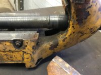
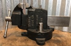
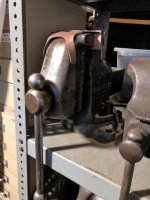
A little while back I acquired this vise. I can’t find anything online about it, it appears to be in good condition but is missing a thrust bearing assembly. It’s a very well made vise with gibs.
Does anyone have a pic of what these parts should look like? I’ve been going through this thread, but haven’t found one that’s made this way. It looks like a block would go in the square hole for a thrust washer or bushing to bear on. I’m a machinist and can make whatever I need, but seeing how it’s supposed to look would help.
i'm curious since you and others are doing these nice pin upgrades holding the vise nuts in place do you have a rule for how tightly you hold the pin in place. do you leave a small gap say 1/8 of an inch or within thousand's of an inch or snug it up?
great stuff and keep up the great work.
i'm curious since you and others are doing these nice pin upgrades holding the vise nuts in place do you have a rule for how tightly you hold the pin in place. do you leave a small gap say 1/8 of an inch or within thousand's of an inch or snug it up?
Picked up a Wilton 1755 Tradesman that appears to have spent time mounted on the back of a concrete form truck. Looks like no hope to get the jaws off without drilling out the screws. Anybody know what size the low head screws are for the jaws and pipe jaws, maybe 1/4-20 x 1/2"? Need to order some stuff from Mcmaster, and would like to order some screws.
TIA, Jim
A common assembly method for American vises is to place the nut in its dovetail in the jaw casting, observe that it fits freely, and has a little bit of lateral play when it is stopped at the front of the dovetail in the jaw. Then. one drives in the retaining-pin, and, using a suitable long drift, bends the retaining-pin down firmly over the nut to lock it in place.
Then, one must slightly free the nut, which is done with the same drift, by driving the nut back 'one whack worth', which should free the nut in its dovetail by the desired .001, allowing the nut whatever freedom of lateral movement it may have, to allow for error in the main screw position. If one gets .002 or .005 of play, no problem, but any more will be noticeable in backlash as the main screw is turned to open the vise. Note that I said 'one whack'.....sometimes it may really take two or three, of decreasingly gentle nature, to free the nut.
cheers
Carla

TX, IIR there is a set screw holding the main screw in place?
Outlaw,
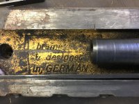
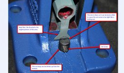
I just noticed these in the back of the vise. The set screw wasn't even up against that threaded piece. Do both of these come out? What happens then? Given that set screw wasn't tight, it isn't intuitively obvious to me what it does or how/what it holds in place and before I remove one or both I'd like to understand what's going on here. ????
Thanks!
A big drag link socket and 1/2'' impact driver will move the big bolt holding the base on.---But soak it in some kind of penetrant first.---Or as some on this thread have done, fashion your own drag link out of a socket and a thick washer.
By the ay Tx, that's a very nice specimen you have there.
")
Pretty simple, the nut is held in place with the set screw pushing the nut forward, looks like some one backed the set screw out and after 40+ years everything is gummed up tight. The set screw block drives up from the bottom and needs to be soaking for a bit to loosen up maybe a little heat will help free up the set screw. The nut is held in by a dove tail slide and maybe soak it in Lacquer thinner for a bit and try to drive it back with a hard wood block, clean everything up and reassemble so your nut floats just a little to help align the Spindle with the nut. Do not forget the grease, it looks like your nut has been dry for a while. Good luck TX.
TX, the setscrew in the side locks the split nut, which is right behind the flattened meatball. It has notches in the face, tap it around counter clockwise with a punch or screwdriver. The center bolt underneath just unscrews counter clockwise like a normal bolt. You need to get the swivel lock free and removed before it will come apart though.
Also, it's your vise, so do what you want, but I don't remove the main nut from the body unless there is a specific problem requiring it. I know some guys like to say they completely disassembled the vise, but seems you can end up making a problem where none existed. YMMV
454,
My reason for wanting to remove the split nut is so I can get the meatball and handle nice and shiny. Yes?
PS
All who care, should I start a separate thread on this topic or leave it here for others to find in the Vise 101 thread?
Thanks!
KMScott,
I wish I could say that I followed all you said but I'd be lying. When you write "the nut" I assume you're referring to the piece that is dove-tailed at the bottom which the vise screw (the "spindle"?) goes into. Correct? That set screw came out very easily by hand. If we're talking about the same set screw. It doesn't appear that the piece that holds the set screw comes out. Or does it? Also, from what you've written it sounds like the "nut" ("holds" the vise screw aka the "spindle"(?) ) is able to travel just a bit forward and backwards. Is that correct? You're suggesting I clean that area. Thinking about it as I write this maybe the "nut" is removable because you couldn't get it in there unless the piece which holds the set screw was removable. That piece does have a slot at the top, so does it unscrew to free the "nut" which could then be slid out the back? Is the piece holding the set screw typically freed with a large screwdriver or maybe a drag link socket (didn't know what these were called so I'm learning a lot here today!).
Thanks!
Sure would be nice if someone had done a thread when they restored their Reed 214 R.
Thanks for all the help guys!
Mike