To avoid these ads, REGISTER NOW!

Connecting vacuum, gauges to mini split?

aunsafe2015

Well-known member
Joined
Apr 2, 2016
Messages
436
Location
Northern VA
I'm having a guy with an EPA cert do my mini split turn on, but I don't know if he's ever done a mini split before, so I am trying to educate myself as much as possible so I can help him out if necessary.

My unit is a Mitsubishi MUZ-FH09NA. I've attached a couple of pictures. It only has a single service port, sticking out to the left of the bottom lineset connection. Can somebody tell me (or point me to a youtube video or website) how exactly a nitrogen tank and vacuum get hooked up to this thing for the nitrogen pressure test and the vacuum?

For the pressure test, would you simply have a single gauge to measure pressure connected to a nitrogen regulator on one end and to the mini split service port on the other end, with a ball valve between the regulator and the gauge? And you would charge to 400 psi or whatever, flip the ball valve to off, then make sure the pressure holds for an appropriate time period?

If that's correct, is there any danger of atmospheric air getting into the lineset when you remove the gauge and nitrogen tank? Or would you use the regulator to release most of the nitrogen, but leave a sufficiently positive pressure of nitrogen in the lineset so that when you disconnect from the service port, nitrogen blows out so that no atmospheric air can get in?

For the vacuum, I take it you would have a vacuum pump connected to a micron gauge then connected to the service port, with a ball valve between the vacuum pump and the micron gauge? Pull the vacuum, switch the ball valve to off, turn off the vacuum pump, and make sure the microns don't rise too much for 30 minutes or whatever?

Now you've got a negative pressure on the lines though, so how do you disconnect from the service port without atmospheric air getting sucked in? Release just enough refrigerant to get a positive charge in the lines, then disconnect from the service value?

Finally, Mitsubishi actually specifies a triple evacuation. I assume for that you'd actually need a manifold gauge with multiple ports. Connect a vacuum pump to one of the ports and a nitrogen tank to another port, with ball valves to isolate them. Pull a vacuum, then turn off ball valve and pump, then release some nitrogen into the system, then pull a vacuum again, etc.?

Sorry for the length of this post, and sorry if I've got it completely wrong. Just trying to make sure this gets done right as it seems like the most important aspect of the installation if I want this mini split to last a long time.

Thanks in advance for any input.

Edit: One last question. On mini splits like this that only have a single service port, does pressuring with nitrogen and pulling the vacuum through the single service port take care of both the liquid and gas lines? I feel like in most of the youtube videos I've watched, the nitrogen or vacuum is getting attached two both lines rather than just one line.
 

Attachments
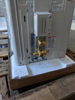
  • IMG_20180718_180157.jpg
    IMG_20180718_180157.jpg
    83.2 KB · Views: 104
  • IMG_20180718_180314.jpg
    IMG_20180718_180314.jpg
    76.4 KB · Views: 86
Last edited:
To avoid these ads, REGISTER NOW!

aardquark

Well-known member
Joined
Aug 27, 2011
Messages
72
I just finished a similar install last night (mine was 06 instead of 09). It was my first, and I learned a lot in the process. Here are the main lessons I learned:

Don't use any old charging hose to pull a vacuum, it will probably leak, especially if it is a cheap one. Charging hoses are made to work under pressure, not vacuum. Get a vacuum rated hose.

When pulling a vacuum and doing the hold test, make sure there are no hoses on the micron gauge side after you close the valve to check for rise in the vacuum level.

Don't use just any old ball valve, it is likely to leak under vacuum. Instead, use a valve core removal tool as a ball valve, they are usually better under vacuum.

Practice removing and replacing the valve core with your core removal tool (CRT) before you starting doing anything. Especially the replacement part, because at the end of this procedure, you will be doing it on a system containing refrigerant.

Having said that, here is what I did:

Initial setup:

Core removal tool (CRT) connected to service port. You need a CRT with a side port. Leave the schrader valve core in the side port.

Remove valve core using the CRT. (Yeah, you could have removed it before you put on the CRT, but it is good practice for a DIYer who doesn't do it every day).

Now put your micron gauge on the side port (don't use a hose, use all brass connected, shortest possible path).

Vacuum-rated hose from back port on the CRT to the vacuum pump. I put an optional ball valve on the vacuum pump end, to avoid blow back of oil when I turn the pump off (we'll call this the pump ball valve).

Turn on vacuum pump, open pump ball valve and the CRT ball valve), and pump it down to medium vacuum (4000 microns or so). Close CRT ball valve, close pump ball valve. We just got rid of most of air & moisture in the line. Now we do a pressure test, and at the same time pick up most of the remaining moisture into the nitrogen.

Pressure test:

Remove vacuum hose from back port of CRT (you have the CRT ball valve closed, right?)

Nitrogen regulator to 0 initially.

Setup hoses as follows:
Nitrogen -> middle port on service gauges.
Low pressure (blue) service gauge closed (don't need that side).
High pressure side (red) connected to outbound
High pressure service gauge valve closed for now.

Turn up nitrogen regulator up to 5 (very small positive pressure).

Open CRT ball valve.

Slowly open high pressure service gauge valve.

Remove micron gauge, it might not be qualified for high pressure. Note that if you have the shrader valve core in the side port of CRT, and the core depressor set correctly, there should be little gas exchange when you do this. Since you already gave it a light positive pressure of nitrogen, no air should be reintroduced in the system when you do so.

Check for gross initial leaks. If none, slowly increase pressure on regulator to your target. For me, it was 350psi. Close the service gauge high pressure valve. This will isolate the system under test from the nitrogen regulator.

Note the pressure on the service gauge. Wait for your desired hold time. An hour seems about right. During that time check for leaks with bubble test. No bubbles, no drop in pressure after your hold time? Good to go. Next step is vacuum purge.

Vacuum purge.

Remove hose from nitrogen supply to middle port of service gauges. Slowly open the high pressure value on service gauges and bleed down to 5 psi or so. Close CRT ball valve, remove hose between back port of CRT and service gauges (high side).

At this point, your lineset is lightly pressurized with nitrogen, held in by the ball valve on the CRT. Now reconnect your vacuum hose to back port on CRT.

Turn on vacuum pump. Open pump ball valve first. This evacuates all the air that is in the vacuum hose, plus the little bit in the outside part of the CRT.

Now reconnect the micro gauge. Again, you have a light positive pressure in system, so when you reconnect, no air gets into the system.

Open CRT ball valve, pump down to a deep vacuum, around 300 microns. When it gets there, leave it running for a while (at least 15 minutes), make sure it stays there or lower.
On the way down, partially close and open the CRT ball valve to get rid of any gas stuck behind the valve.

When you have established a stable low vacuum (300 or lower), close the CRT ball valve. You can expect a very slow rise, but it should not rise higher than 500 in 15 minutes. If you have met this goal, you have successfully purged your system of moisture.

Opening the refrigerant ports:

Keeping the CRT ball valve closed, crack open the refridgerant valves a bit, this introduces refrigerant in vapor form into your vacuum.

Now you need to put the valve core back into the service port. Google it. Note that the stem that you use to push the valve core back into position will be under pressure. Keep a steady push, but gentle, and you will get the job done. Note that in order to put back the valve core, you needed to open the CRT valve. To see if you are doing things correctly, you can pull the stem back, and reclose the CRT valve. Remove the stem from back port of CRT, look at it. If it still has a valve core on it, you messed up, try again.

If you completed all the above steps correctly, you should be able to remove the CRT, and the system will hold pressure. Test the service port with bubble test. You might have to (gently) snug up the valve core.

Now open both your refrigerant valves fully, replace cover caps (three of them), and you are good to go. Enjoy your new system!
 
Last edited:

bzinsky

Well-known member
Joined
Oct 27, 2014
Messages
5,565
Fyi holding the nitrogen pressure is baloney. The pressure gauge is not accurate enough. It’s not like you’re going to notice if you started with 350psi and then 8 hours later it’s 349psi.

I Did 20 units at one time. Pressurize them and then test the connections with soap and water. You don’t need to wait. You need to look at the connections VERY closely. Some of them have incredibly small leaks, like the kind that would take the system months to depressurize. You’ll never find them following protocol, which tells you to watch the pressure of a length of time. If they pass the soap and water test you’re good.

Also vacuuming them down is a great way to check for leaks too. I had atleast 5 out of my 80 flare connections that I caught during vacuum. The only way I could locate them to fix them was repressurizing with nitrogen, which is when I discovered soap and water is way better than letting them sit pressurized for 24 hours.

I took mine down to 50-100 microns.

Make sure the guy does this and that he waits until the microns stop rising. Any moisture in the line will start to boil under that much vacuum. So when you take it down real low and turn the vacuum pump off it will start to rise slowly, because the moisture is boiling off. Give it like 5 minutes under vacuum and make sure it levels off and holds.

It easy to tell the difference between moisture and a leak while watching the micron gauge
 

bzinsky

Well-known member
Joined
Oct 27, 2014
Messages
5,565
Wish I had known about that stuff

i was looking at those flare joints from like 5 inches away and eventually would see these iddy bitty bubbles, and was like ah ha!

i’d imagine that solution would make it much easier
 
OP
A

aunsafe2015

Well-known member
Joined
Apr 2, 2016
Messages
436
Location
Northern VA
I just finished a similar install last night (mine was 06 instead of 09). It was my first, and I learned a lot in the process. Here are the main lessons I learned:

Don't use any old charging hose to pull a vacuum, it will probably leak, especially if it is a cheap one. Charging hoses are made to work under pressure, not vacuum. Get a vacuum rated hose.

When pulling a vacuum and doing the hold test, make sure there are no hoses on the micron gauge side after you close the valve to check for rise in the vacuum level.

Don't use just any old ball valve, it is likely to leak under vacuum. Instead, use a valve core removal tool as a ball valve, they are usually better under vacuum.

Practice removing and replacing the valve core with your core removal tool (CRT) before you starting doing anything. Especially the replacement part, because at the end of this procedure, you will be doing it on a system containing refrigerant.

Having said that, here is what I did:

Initial setup:

Core removal tool (CRT) connected to service port. You need a CRT with a side port. Leave the schrader valve core in the side port.

Remove valve core using the CRT. (Yeah, you could have removed it before you put on the CRT, but it is good practice for a DIYer who doesn't do it every day).

Now put your micron gauge on the side port (don't use a hose, use all brass connected, shortest possible path).

Vacuum-rated hose from back port on the CRT to the vacuum pump. I put an optional ball valve on the vacuum pump end, to avoid blow back of oil when I turn the pump off (we'll call this the pump ball valve).

Turn on vacuum pump, open pump ball valve and the CRT ball valve), and pump it down to medium vacuum (4000 microns or so). Close CRT ball valve, close pump ball valve. We just got rid of most of air & moisture in the line. Now we do a pressure test, and at the same time pick up most of the remaining moisture into the nitrogen.

Pressure test:

Remove vacuum hose from back port of CRT (you have the CRT ball valve closed, right?)

Nitrogen regulator to 0 initially.

Setup hoses as follows:
Nitrogen -> middle port on service gauges.
Low pressure (blue) service gauge closed (don't need that side).
High pressure side (red) connected to outbound
High pressure service gauge valve closed for now.

Turn up nitrogen regulator up to 5 (very small positive pressure).

Open CRT ball valve.

Slowly open high pressure service gauge valve.

Remove micron gauge, it might not be qualified for high pressure. Note that if you have the shrader valve core in the side port of CRT, and the core depressor set correctly, there should be little gas exchange when you do this. Since you already gave it a light positive pressure of nitrogen, no air should be reintroduced in the system when you do so.

Check for gross initial leaks. If none, slowly increase pressure on regulator to your target. For me, it was 350psi. Close the service gauge high pressure valve. This will isolate the system under test from the nitrogen regulator.

Note the pressure on the service gauge. Wait for your desired hold time. An hour seems about right. During that time check for leaks with bubble test. No bubbles, no drop in pressure after your hold time? Good to go. Next step is vacuum purge.

Vacuum purge.

Remove hose from nitrogen supply to middle port of service gauges. Slowly open the high pressure value on service gauges and bleed down to 5 psi or so. Close CRT ball valve, remove hose between back port of CRT and service gauges (high side).

At this point, your lineset is lightly pressurized with nitrogen, held in by the ball valve on the CRT. Now reconnect your vacuum hose to back port on CRT.

Turn on vacuum pump. Open pump ball valve first. This evacuates all the air that is in the vacuum hose, plus the little bit in the outside part of the CRT.

Now reconnect the micro gauge. Again, you have a light positive pressure in system, so when you reconnect, no air gets into the system.

Open CRT ball valve, pump down to a deep vacuum, around 300 microns. When it gets there, leave it running for a while (at least 15 minutes), make sure it stays there or lower.
On the way down, partially close and open the CRT ball valve to get rid of any gas stuck behind the valve.

When you have established a stable low vacuum (300 or lower), close the CRT ball valve. You can expect a very slow rise, but it should not rise higher than 500 in 15 minutes. If you have met this goal, you have successfully purged your system of moisture.

Opening the refrigerant ports:

Keeping the CRT ball valve closed, crack open the refridgerant valves a bit, this introduces refrigerant in vapor form into your vacuum.

Now you need to put the valve core back into the service port. Google it. Note that the stem that you use to push the valve core back into position will be under pressure. Keep a steady push, but gentle, and you will get the job done. Note that in order to put back the valve core, you needed to open the CRT valve. To see if you are doing things correctly, you can pull the stem back, and reclose the CRT valve. Remove the stem from back port of CRT, look at it. If it still has a valve core on it, you messed up, try again.

If you completed all the above steps correctly, you should be able to remove the CRT, and the system will hold pressure. Test the service port with bubble test. You might have to (gently) snug up the valve core.

Now open both your refrigerant valves fully, replace cover caps (three of them), and you are good to go. Enjoy your new system!

Awesome write up. I'll read this in great detail tomorrow and may have additional questions, but a few now:

1) where did you see 350 psi for the nitrogen test? My installation manual actually doesn't seem to specify. That number sounds about right but I'm just curious if you saw it in Mitsubishi documentation somewhere?

2) clever idea to switch between nitrogen and vacuum connected to your CRT. When you are talking about "service gauges" I assume you mean a 3-port set of manifold gauges, something like this: https://www.amazon.com/dp/B004N19WAG/?tag=atomicindus08-20

Correct?

3) is the CRT really necessary? I have read a fair amount about them and they seem to speed the process up by making it quicker to pull a deep vacuum, but wouldn't a high quality tee with a ball valve on it serve essentially the same function? Is your primary reason for using the CRT over a tee just because you think the tee is more likely to leak?

Is this an example of the type of CRT you used?
https://express.google.com/u/0/prod...campaign=gsx&dclid=CMaZ3sK6rNwCFam5swodZfMMjA

Thanks so much for the detailed write up. And thanks for the other responses, too. Very helpful.
 
OP
A

aunsafe2015

Well-known member
Joined
Apr 2, 2016
Messages
436
Location
Northern VA
Wish I had known about that stuff

i was looking at those flare joints from like 5 inches away and eventually would see these iddy bitty bubbles, and was like ah ha!

i’d imagine that solution would make it much easier
What sort of solution were you using?
 

justinjoyal

Well-known member
Joined
Apr 30, 2015
Messages
888
Location
Quebec
Fyi holding the nitrogen pressure is baloney. The pressure gauge is not accurate enough. It’s not like you’re going to notice if you started with 350psi and then 8 hours later it’s 349psi.

I Did 20 units at one time. Pressurize them and then test the connections with soap and water. You don’t need to wait. You need to look at the connections VERY closely. Some of them have incredibly small leaks, like the kind that would take the system months to depressurize. You’ll never find them following protocol, which tells you to watch the pressure of a length of time. If they pass the soap and water test you’re good.

Also vacuuming them down is a great way to check for leaks too. I had atleast 5 out of my 80 flare connections that I caught during vacuum. The only way I could locate them to fix them was repressurizing with nitrogen, which is when I discovered soap and water is way better than letting them sit pressurized for 24 hours.

I took mine down to 50-100 microns.

Make sure the guy does this and that he waits until the microns stop rising. Any moisture in the line will start to boil under that much vacuum. So when you take it down real low and turn the vacuum pump off it will start to rise slowly, because the moisture is boiling off. Give it like 5 minutes under vacuum and make sure it levels off and holds.

It easy to tell the difference between moisture and a leak while watching the micron gauge


Vacuum should not be used to pressure test.

Quality digital gauges work great for pressure testing.
 

Ohmthis

Well-known member
Joined
Jan 20, 2013
Messages
3,018
Location
Outside of Louisville KY
Vacuum should not be used to pressure test.

Quality digital gauges work great for pressure testing.

I don’t believe he is saying to bypass the pressure test and leak check with vacuum. My take is he is saying that after a successful pressure test he still found leaks. That some leaks are found using vacuum.
 

bonneyman

Well-known member
Joined
Apr 22, 2010
Messages
8,852
Location
Desert SW

aardquark

Well-known member
Joined
Aug 27, 2011
Messages
72
1) where did you see 350 psi for the nitrogen test? My installation manual actually doesn't seem to specify. That number sounds about right but I'm just curious if you saw it in Mitsubishi documentation somewhere?
Not from Mitsubishi documentation. Consensus in online sources that I trust seems to be in that range. For example: http://hvac-talk.com

2) clever idea to switch between nitrogen and vacuum connected to your CRT. When you are talking about "service gauges" I assume you mean a 3-port set of manifold gauges, something like this: https://www.amazon.com/dp/B004N19WAG/?tag=atomicindus08-20

Correct?
Yes, that's the item. For a small mini-split like the one I worked on with only one service port, you only need one side (only one gauge). I have seen a few of them, but ended up getting the normal kind with two gauges.

3) is the CRT really necessary? I have read a fair amount about them and they seem to speed the process up by making it quicker to pull a deep vacuum, but wouldn't a high quality tee with a ball valve on it serve essentially the same function? Is your primary reason for using the CRT over a tee just because you think the tee is more likely to leak?

Is this an example of the type of CRT you used?
https://express.google.com/u/0/prod...campaign=gsx&dclid=CMaZ3sK6rNwCFam5swodZfMMjA
Yes, that's the CRT. That seems to be the standard way to do the job with a minimum of hardware. Mine was Yellow Jacket branded, not especially pricey, but was vacuum rated. I think if you use it you need to remove the valve core, because it doesn't have a core depressor. Also, a tee probably does not have an integral ball valve, so now you are introducing another point of failure. (That is actually how I started, and had lots of problems with vacuum leaks before I figured out that the CRT could actually be used as a tee, with a ball valve). I guess if you could find a tee with a vacuum rated ball valve AND it had a female connection on one end with a valve core depressor, you could eliminate removal of the core, but at the expense of leaking a little bit of refrigerant when you remove it at the end of the process. In my opinion, the CRT is a better choice, because it actually meets all the requirements, and is much easier to find. It's not that hard to put the core back in.
 

LS6 Tommy

Well-known member
Joined
Dec 27, 2013
Messages
26,162
Location
Northern NJ
The max test pressure should be listed on the unit ID tag. Aardquark, your leak test/evacuation procedure is about the best written one I've seen. Pretty much identical to what I've always done.


Tommy
 

brewchief

Well-known member
Joined
Sep 20, 2008
Messages
2,370
Location
Michigan
Most mini splits have a 5/16" connection, most gauge sets are 1/4" so you need an adapter, the core removel tool I have is also the adapter. I use a ball valve on the side port on the core removel tool so I can isolate my vacuum gauge so it's not exposed to the refrigerant pressure and oil when the service valves are opened.

Sent from my XT1254 using Tapatalk
 
To avoid these ads, REGISTER NOW!
OP
A

aunsafe2015

Well-known member
Joined
Apr 2, 2016
Messages
436
Location
Northern VA
Vacuum-rated hose from back port on the CRT to the vacuum pump. I put an optional ball valve on the vacuum pump end, to avoid blow back of oil when I turn the pump off (we'll call this the pump ball valve).

So your setup is vacuum pump, then somewhere between vacuum pump and back port of the CRT, a vacuum rated ball valve? Any idea whether it would be preferable to place the ball valve closer to the CRT or the pump itself? [edit: oh, by "vacuum pump end" I assume you mean you put the ball valve closer to the pump than to the CRT]

Setup hoses as follows:
Nitrogen -> middle port on service gauges.
Low pressure (blue) service gauge closed (don't need that side).
High pressure side (red) connected to outbound
High pressure service gauge valve closed for now.

By outbound, you mean connect a hose from the red gauge to the 1/4” port on the CRT where the vacuum pump was previously connected?

So your overall setup is nitrogen tank -> regulator -> hose -> middle port of service gauge; then red gauge -> hose -> 1/4” port on CRT where vacuum pump was previously connected. Correct?


Check for gross initial leaks. If none, slowly increase pressure on regulator to your target. For me, it was 350psi. Close the service gauge high pressure valve. This will isolate the system under test from the nitrogen regulator.

This probably just reflects my lack of understanding about how manifold gauges work, but after you close the service gauge high pressure valve, how is the gauge still reading the pressure in the lineset? Is it b/c the service gauge high pressure valve keeps the gauge itself in fluid communication with the lineset, but simply kills the link between the nitrogen tank and the lineset?

Keeping the CRT ball valve closed, crack open the refridgerant valves a bit, this introduces refrigerant in vapor form into your vacuum.

So you open it a little bit and leave it open while you replace the Schrader valve core? Your micron gauge will still be connected at this point, correct? So would it be better to let enough refrigerant in to get a small positive pressure, as read on the micron gauge, and then to re-close the refrigerant valve before putting the Schrader core back in?

Note that in order to put back the valve core, you needed to open the CRT valve. To see if you are doing things correctly, you can pull the stem back, and reclose the CRT valve. Remove the stem from back port of CRT, look at it. If it still has a valve core on it, you messed up, try again.

When you open the CRT valve, some of the refrigerant will theoretically escape through the open CRT valve, correct?

So is it accurate to say you crack the refrigerant valve, then open the CRT valve, then as soon as possible after opening the CRT valve, you reinstall the Schrader core? With the goal of minimizing any refrigerant escape?

Thanks again for the excellent info.
 
Last edited:
OP
A

aunsafe2015

Well-known member
Joined
Apr 2, 2016
Messages
436
Location
Northern VA
Most mini splits have a 5/16" connection, most gauge sets are 1/4" so you need an adapter, the core removel tool I have is also the adapter. I use a ball valve on the side port on the core removel tool so I can isolate my vacuum gauge so it's not exposed to the refrigerant pressure and oil when the service valves are opened.

Sent from my XT1254 using Tapatalk

Yeah, this CRT looks like it is 5/16": https://www.amazon.com/dp/B008HQ2EZ8/?tag=atomicindus08-20.

Asked above, but wouldn't you want to be able to measure pressure when the refrigerant valve is opened so you can know how much refrigerant you have released? Wouldn't it be best to release small amount of refrigerant to get a positive pressure in the lines, then close the refrigerant valve, then re-install the Schrader core while the refrigerant valve is closed?
 

brewchief

Well-known member
Joined
Sep 20, 2008
Messages
2,370
Location
Michigan
Yeah, this CRT looks like it is 5/16": https://www.amazon.com/dp/B008HQ2EZ8/?tag=atomicindus08-20.

Asked above, but wouldn't you want to be able to measure pressure when the refrigerant valve is opened so you can know how much refrigerant you have released? Wouldn't it be best to release small amount of refrigerant to get a positive pressure in the lines, then close the refrigerant valve, then re-install the Schrader core while the refrigerant valve is closed?
That's the core removel tool that I have, I will open the service valves fully and then reinstall the cores, when you go to install the core you want to leave the nut on the back of the core puller slightly loose so you can purge any air out, as soon as you crack open the valve on the CRT and refrigerant starts coming out you can fully tighten it up and then reinstall the valve core.

I use a ball valve on the side port to connect the vacuum gauge, on my 5/16" CRT the ball valves valve depressor won't depress the valve core so I pull it, no big deal but I can't remove the ball valve until I remove the whole thing.
Here is a pic of my setup, it's on a regular A/C but principal is the same.b3e0d1ace4411850fb1c6aa9caf8f63e.jpg

Sent from my XT1254 using Tapatalk
 

Attachments

  • b3e0d1ace4411850fb1c6aa9caf8f63e.jpg
    b3e0d1ace4411850fb1c6aa9caf8f63e.jpg
    161.2 KB · Views: 7

aardquark

Well-known member
Joined
Aug 27, 2011
Messages
72
So your setup is vacuum pump, then somewhere between vacuum pump and back port of the CRT, a vacuum rated ball valve? Any idea whether it would be preferable to place the ball valve closer to the CRT or the pump itself? [edit: oh, by "vacuum pump end" I assume you mean you put the ball valve closer to the pump than to the CRT]
The purpose of the 'pump valve' is to keep oil from blowing back into the hose when I turn off the vacuum pump. I have a very basic pump, and my experience is that a lot of oil can end up in the hose, and then on to everything else, including the micron gauge if I'm not careful. So to do this job well, that valve should be close to the pump. It doesn't have to be very good at holding a vacuum, because we are not going to use it for the vacuum hold test, but it does have to be good enough so your pump can evacuate faster than it leaks. I just used a regular ball valve, one of these.


By outbound, you mean connect a hose from the red gauge to the 1/4” port on the CRT where the vacuum pump was previously connected?

So your overall setup is nitrogen tank -> regulator -> hose -> middle port of service gauge; then red gauge -> hose -> 1/4” port on CRT where vacuum pump was previously connected. Correct?

This probably just reflects my lack of understanding about how manifold gauges work, but after you close the service gauge high pressure valve, how is the gauge still reading the pressure in the lineset? Is it b/c the service gauge high pressure valve keeps the gauge itself in fluid communication with the lineset, but simply kills the link between the nitrogen tank and the lineset?
Yes, you understand the connections correctly. The gauge is connected in such a way that when the (red) valve is closed, it still senses pressure to the (red) line, i.e. the outbound line on the right hand side (at least it is right hand side for my gauge set). If you reversed the hoses, you could still pressurize the system, but when you close the valve, the gauge would not be able to sense the pressure in the system.

So you open it a little bit and leave it open while you replace the Schrader valve core? Your micron gauge will still be connected at this point, correct? So would it be better to let enough refrigerant in to get a small positive pressure, as read on the micron gauge, and then to re-close the refrigerant valve before putting the Schrader core back in?
Yes, that would work too, but note that the way a CRT works is to replace the valve core under pressure. The back side has seals. The only refrigerant that leaks is a tiny bit that is captured inside the CRT. Probably less than a cc. Also note that when you bleed out the nitrogen, you still have the service (manifold) gauge connected, so you can just look at that. Also, your micro gauge may not sense positive pressure. I have a uBluVac, and I never noticed it say anything other than HiPressure or something like that for ambient or positive pressure. (By the way, I was told by the guy who invented it that this particular gauge is tested at high positive pressure, but I removed it anyway before the high pressure test.)

When you open the CRT valve, some of the refrigerant will theoretically escape through the open CRT valve, correct?

So is it accurate to say you crack the refrigerant valve, then open the CRT valve, then as soon as possible after opening the CRT valve, you reinstall the Schrader core? With the goal of minimizing any refrigerant escape?
You don't open the CRT valve until you have inserted the stem in the back port (loaded with a valve core) and screwed it onto the port. The CRT tool does a pretty good job of preventing leaks, so you can take your time. You might want to just experiment with this when you are bleeding out the nitrogen. Don't do it with full pressure, but give a try replacing the valve core when the (nitrogen) pressure is down to 50psi or so, just so you get some experience. Just take it back out before you pull a vacuum.

Thanks again for the excellent info.
I appreciate that. I'm not trying to step on anybody's toes, or claim I am an expert, this is just my experience. There were a lot of little things that I did not understand at first, that someone with experience probably already knows, so I tried to be as thorough as possible, to help the next guy (who is new to this).

Regarding a previous comment that watching for the nitrogen gauge to drop is probably not a very good test, I agree that it will only find a gross leak. Tiny leaks require bubble test and if they are very tiny, even that may be hard to spot. I guess the next step would be a sniffer, but I expect that is an expensive piece of equipment that I am not prepared to buy for a small number of personal installs. I will take the chance, and if I missed something, it's probably cheaper (and more effective) for me to call in an experienced technician.
 

eddieK

Well-known member
Joined
Mar 2, 2017
Messages
695
Location
Nampa Idaho
350 to 400 nitrogen test does not tell you where you have a leak, it can show if you have one.

Thick Nu calgon works really well to find small leaks.

The reason you do a triple vacuum is that moisture trapped in the oil freezes at the low pressure (29.99 Hg) and it doesn't boil off... by re introducing the nitrogen the trapped moisture melts, you find that each evac goes much faster.

The general rule of thumb is...when you isolate (ball valve) the system under vacuum, if it rises to less than 1000, no leak, but moisture may still be present, if it rises above 1000 you most likely have a leak.
 
OP
A

aunsafe2015

Well-known member
Joined
Apr 2, 2016
Messages
436
Location
Northern VA
The purpose of the 'pump valve' is to keep oil from blowing back into the hose when I turn off the vacuum pump. I have a very basic pump, and my experience is that a lot of oil can end up in the hose, and then on to everything else, including the micron gauge if I'm not careful. So to do this job well, that valve should be close to the pump. It doesn't have to be very good at holding a vacuum, because we are not going to use it for the vacuum hold test, but it does have to be good enough so your pump can evacuate faster than it leaks. I just used a regular ball valve, one of these.


Yes, you understand the connections correctly. The gauge is connected in such a way that when the (red) valve is closed, it still senses pressure to the (red) line, i.e. the outbound line on the right hand side (at least it is right hand side for my gauge set). If you reversed the hoses, you could still pressurize the system, but when you close the valve, the gauge would not be able to sense the pressure in the system.


Yes, that would work too, but note that the way a CRT works is to replace the valve core under pressure. The back side has seals. The only refrigerant that leaks is a tiny bit that is captured inside the CRT. Probably less than a cc. Also note that when you bleed out the nitrogen, you still have the service (manifold) gauge connected, so you can just look at that. Also, your micro gauge may not sense positive pressure. I have a uBluVac, and I never noticed it say anything other than HiPressure or something like that for ambient or positive pressure. (By the way, I was told by the guy who invented it that this particular gauge is tested at high positive pressure, but I removed it anyway before the high pressure test.)


You don't open the CRT valve until you have inserted the stem in the back port (loaded with a valve core) and screwed it onto the port. The CRT tool does a pretty good job of preventing leaks, so you can take your time. You might want to just experiment with this when you are bleeding out the nitrogen. Don't do it with full pressure, but give a try replacing the valve core when the (nitrogen) pressure is down to 50psi or so, just so you get some experience. Just take it back out before you pull a vacuum.


I appreciate that. I'm not trying to step on anybody's toes, or claim I am an expert, this is just my experience. There were a lot of little things that I did not understand at first, that someone with experience probably already knows, so I tried to be as thorough as possible, to help the next guy (who is new to this).

Regarding a previous comment that watching for the nitrogen gauge to drop is probably not a very good test, I agree that it will only find a gross leak. Tiny leaks require bubble test and if they are very tiny, even that may be hard to spot. I guess the next step would be a sniffer, but I expect that is an expensive piece of equipment that I am not prepared to buy for a small number of personal installs. I will take the chance, and if I missed something, it's probably cheaper (and more effective) for me to call in an experienced technician.

Awesome, thanks again. I think I understand now. Didn't realize the CRT had back seals that prevent it from leaking refrigerant while the core is being reinstalled. That makes sense.
 

Worsedog

Well-known member
Joined
Mar 2, 2008
Messages
1,515
Location
Central FL
350 to 400 nitrogen test does not tell you where you have a leak, it can show if you have one.

Thick Nu calgon works really well to find small leaks.

The reason you do a triple vacuum is that moisture trapped in the oil freezes at the low pressure (29.99 Hg) and it doesn't boil off... by re introducing the nitrogen the trapped moisture melts, you find that each evac goes much faster. The evac goes faster each time because to the amount of moisture boiled off gets smaller with each cycle.

The general rule of thumb is...when you isolate (ball valve) the system under vacuum, if it rises to less than 1000, no leak, but moisture may still be present, if it rises above 1000 you most likely have a leak.

The vacuum is what causes the moisture to boil off, not the introduction of the nitrogen. The nitrogen is used as a pressure testing and purging agent because it is dry. Regular air would physically do the pressure testing job, but then you'd be putting moisture back into the system. The evac goes faster each time because the volume of water is reduced with each cycle.
 
Last edited:

LS6 Tommy

Well-known member
Joined
Dec 27, 2013
Messages
26,162
Location
Northern NJ
The reason you do a triple vacuum is that moisture trapped in the oil freezes at the low pressure (29.99 Hg) and it doesn't boil off... by re introducing the nitrogen the trapped moisture melts, you find that each evac goes much faster.

Moisture in a closed HVAC boils under a vacuum, liquid water freezes. Unless something was done VERY wrong, there is never liquid water in a system.

Tommy
 

eddieK

Well-known member
Joined
Mar 2, 2017
Messages
695
Location
Nampa Idaho
The vacuum is what causes the moisture to boil off, not the introduction of the nitrogen. The nitrogen is used as a pressure testing and purging agent because it is dry. Regular air would physically do the pressure testing job, but then you'd be putting moisture back into the system. The evac goes faster each time because the volume of water is reduced with each cycle.

Read it again...The nitrogen re- introduction defrosts it back to a vapor allowing it to be removed. Deep vacuums make the moisture trapped in the oil freeze, your vacuum pump does not remove this...that is why manufacturers always recommend a triple vacuum.
 
Last edited:

Trey T

Well-known member
Joined
Aug 3, 2011
Messages
3,749
Location
Houston, TX
Just a reminder ... the term "boil" --like boiling of water on stove-- is not to heat it up. For our topic here, the term "boil" is to lower the pressure to the point of liquid phase change to vapor/gas phase.

Theoretically, if there's no oil (or contaminant) in the line, then you don't need to use nitrogen. The vacuum will force all water to turn into gas and gets pulled out. Nitrogen, soluble to water, is needed to pull the water molecule away from contaminant. The triple vacuum (i call it triple nitrogen rinse) is needed because the nitrogen has relatively low solubility limit, limiting the volume of water it can be dissolved and carry out of the lineset/system, forcing the user to inject more nitrogen a second and third time. You can see why I call it "triple nitrogen rinse" because "triple vacuum" doesn't make a whole lot of sense.
 

Worsedog

Well-known member
Joined
Mar 2, 2008
Messages
1,515
Location
Central FL
Read it again...The nitrogen re- introduction defrosts it back to a vapor allowing it to be removed. Deep vacuums make the moisture trapped in the oil freeze, your vacuum pump does not remove this...that is why manufacturers always recommend a triple vacuum.

Understand how it works...Water boils in a vacuum at room or your outdoor ambient temperature. When the water boils the vacuum pump does remove the vapor caused by the boiling. The nitrogen purge may help move the vapor along but it thaws nothing because nothing is frozen because of the vacuum. The reason for the triple vacuum cycle is to insure all contaminants and moisture is out, that part you have correct. The theory on how it works is not.
 

brewchief

Well-known member
Joined
Sep 20, 2008
Messages
2,370
Location
Michigan
Understand how it works...Water boils in a vacuum at room or your outdoor ambient temperature. When the water boils the vacuum pump does remove the vapor caused by the boiling. The nitrogen purge may help move the vapor along but it thaws nothing because nothing is frozen because of the vacuum. The reason for the triple vacuum cycle is to insure all contaminants and moisture is out, that part you have correct. The theory on how it works is not.

https://hvacrschool.com/can-pulling-vacuum-fast-freeze-water-moisture/

Moisture can freeze when pulling a vacuum, I think in practice it's not real common but the theory is correct.
 
OP
A

aunsafe2015

Well-known member
Joined
Apr 2, 2016
Messages
436
Location
Northern VA
I appreciate that. I'm not trying to step on anybody's toes, or claim I am an expert, this is just my experience. There were a lot of little things that I did not understand at first, that someone with experience probably already knows, so I tried to be as thorough as possible, to help the next guy (who is new to this).

Aardquark, I sent you a PM with a few other questions about whether the louvers of your indoor unit were secured by tape, and about the foam in the cavity on the back of the unit (which I assume is NOT supposed to be removed, but I just want to make sure).

Thanks again for all your help.
 

LS6 Tommy

Well-known member
Joined
Dec 27, 2013
Messages
26,162
Location
Northern NJ
https://hvacrschool.com/can-pulling-vacuum-fast-freeze-water-moisture/

Moisture can freeze when pulling a vacuum, I think in practice it's not real common but the theory is correct.

No, it can't. Only liquid water freezes under a "fast" vacuum. Moisture (water vapor) boils off. Even then, it only happens in the classic lab demonstration where the container has a VERY small volume and is filled about 1/4 full of water. It's also made out of glass, which insulates the water from the heat content in the surrounding air. The heat removed from boiling is not replaced by the heat in the ambient air as fast, so the water freezes. I've seen the demonstration done a bunch of times. I've also seen it done where the container was made out of copper with a glass observation port. The water did not freeze.

In an actual HVAC system there are two main reasons why it can't happen:

First, the volume is large enough that there is just no way to pull it down fast enough to cause freezing.
Second, the system is made out of metals that conduct heat content from the ambient air very well, so as the moisture boils off and heat is removed, it is immediately added again and the moisture just continues to boil off.

As I said before, if you have ANY liquid water in your system, something is VERY wrong. :thumbup:

Tommy
 
Last edited:
To avoid these ads, REGISTER NOW!
Top Bottom