To avoid these ads, REGISTER NOW!

Can a thermostat independently control compressor and compressor fan?

TT_Vert

Well-known member
Joined
Mar 9, 2018
Messages
1,436
Location
Wauconda, IL.
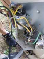
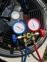
Reason I ask is that I am noticing that there are times the fan for compressor is running but not compressor then a bit later the compressor will come on (Doesn't seem to be consistent and can be 10-20 minutes all the while temp goes up a degree or two). I have a nest thermostat but i didn't think that would be possible. I did test the capacitance of both sides of the start/run cap and all are well within specs. I also checked the pressure when this is occurring and it doesn't seem too high or low (75/200) @85 ambient so any high/low pressure cutoffs should not be causing this. If this has a high/low pressure switch it must be somewhere in the compressor housing as following the wires from the contactor to cap and then from there it goes right into the compressor housing. I also ensured I had 110 on both legs before and after contactor when this was occurring.

I wonder if my compressor is on the way out. It is certainly cooling well (about 18 degrees difference intake to exhaust air) and it feels fine in the garage. I'm just concerned here as I would assume the compressor would be on any time the compressor fan is on.

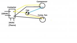
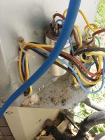
I've include a few pics including the schematic.

Thanks much

Dave
 

Attachments

  • 2018-08-08 18.51.27.jpg
    2018-08-08 18.51.27.jpg
    84.4 KB · Views: 54
  • 2018-08-08 18.51.37.jpg
    2018-08-08 18.51.37.jpg
    96.7 KB · Views: 57
  • 2018-08-08 18.51.14.jpg
    2018-08-08 18.51.14.jpg
    135 KB · Views: 63
  • 2018-08-08 18.51.00.jpg
    2018-08-08 18.51.00.jpg
    80 KB · Views: 46
To avoid these ads, REGISTER NOW!

ant.foste

Well-known member
Joined
Aug 14, 2016
Messages
403
Location
Maryland
The next time you notice this, disconnect all wiring going to the compressor and ohm the compressor windings. You'll want to determine if the compressor is turning off on thermal overload. There is a thermal switch in the compressor that will open a winding if it gets too hot, effectively turning off the compressor to cool down, while leaving the condenser fan on.
 
OP
T

TT_Vert

Well-known member
Joined
Mar 9, 2018
Messages
1,436
Location
Wauconda, IL.
I think this also occurs on initial start so the compressor wouldn't' be hot yet but I'll definitely try that. There are blue/black and yellow coming out. It looks like blue/yellow are the motor windings, could you perhaps confirm that in the wiring diag. I posted? Want to make sure I'm ohming out the right wires.

Dave
 

Trey T

Well-known member
Joined
Aug 3, 2011
Messages
3,749
Location
Houston, TX
No.

Your photos only shows two components but your schematic shows about 10+ components that appears you don't have. Redraw the connection diagram based on what your system have and let us know what you have and don't have.
 

matt_i

Well-known member
Joined
Mar 14, 2008
Messages
10,729
Location
SE Michigan
I only see one contactor on there -CONT- which seems to indicate they should both run and shutdown at the same time.

Sometimes the capacitor has one side for compressor and one side for fan (one value for each as a dual capacitor in the same "can") If one part of that capacitor is approaching life-end it could trigger some wonky behavior with starting one part or the other.
 

eddieK

Well-known member
Joined
Mar 2, 2017
Messages
695
Location
Nampa Idaho
Check your filter first - then check and see if the outdoor coil is clean (you should be able to see through it). Check your air delivery at the supply air outlets, if it is weak after filter is removed the evaporator coil is clogged. Any of these conditions cause excess pressures and can in fact at times send liquid to the compressor (slugging).

The contactor can appear to be okay, but look close - are the contacts burned? Also what are you using to determine the proper UF from the capacitor? The simplest test for a run capacitor (considering how inexpensive they are and that they are considered a consumable is to replace or test with one 10% higher rating).

That appears to be an 05 model - I recommend replacing the capacitor AND contactor at that age.
 
Last edited:

brewchief

Well-known member
Joined
Sep 20, 2008
Messages
2,370
Location
Michigan
What type of metering device does the indoor coil have? I have seen systems with a TXV that doesn't have bleed ports not be able to start the compressor if it hasn't had a long enough time for the pressure to equalize, adding a hard start kit cured it. It might not have shown itself with an older stat that has a longer tine between cycles where something like a nest tries keeping the temp very close to the setpoint.

Sent from my XT1254 using Tapatalk
 

bonneyman

Well-known member
Joined
Apr 22, 2010
Messages
8,829
Location
Desert SW
Could be a "sticky" contactor. I've seen ants and other bugs who crawl across the contactor contacts, and if there's any creature there when the contactor closes, the bug guts carbonize and ruin the contacts. The fan might get enough power to start but the comp needs alot more, and gummed contacts might not pass the power necessary. Then after it warms up it might make enough contact for the comp. Easy enough to check, contact cleaner might save the switch.

Also, remove one of the freon caps, and depress the valve core momentarily. See if it smells burnt in any way. Should be odorless or an oily smell. Any burntness indicates trouble brewing. They also make disposable acid test kits that work off of the schrader valves as well if you want a definitive test with percentages.

https://www.amazon.com/dp/B0119R6RFY/?tag=atomicindus08-20
 

rlitman

Well-known member
Joined
Oct 18, 2010
Messages
24,624
Location
Long Island
... I am noticing that there are times the fan for compressor is running but not compressor then a bit later the compressor will come on ...

This is definitely not right, and you need to fix this.

The opposite however may be ok. Many fans have variable speed controllers that delay fan operation based on refrigerant pressure, so the compressor will be running for a little before the fan kicks in.
 
OP
T

TT_Vert

Well-known member
Joined
Mar 9, 2018
Messages
1,436
Location
Wauconda, IL.
I only see one contactor on there -CONT- which seems to indicate they should both run and shutdown at the same time.

Sometimes the capacitor has one side for compressor and one side for fan (one value for each as a dual capacitor in the same "can") If one part of that capacitor is approaching life-end it could trigger some wonky behavior with starting one part or the other.

Sorry for the delay guys, I was not notified of this. Matt you are correct this is a dual cap. I did check capacitance on both sides w/ my DVOM and both are well within spec and none of the typical bulging you'd see from a cap on its way out.

Before i get into more detail i'll say i checked all obvious things and I'll reiterate a few.

1. I'm getting 220 on the other side of contactor so that's out.
2. Air filter is new/checked, no restriction
3. Condenser coil looks as good as the day it was installed., No debris blocking airflow.
4. Single contactor activated by 24VAC from thermostat (confirmed 24V is there). Confirmed 220VAC on other side of contactor when the compressor is NOT running but fan is on. There appears to be only one coil in the contactor so I cannot see them being started independently.


@TrayT
I went through the wiring before posting which is why I had mentioned that right from the cap it goes right into the compressor. So unless the high/low pressure switches and/or the delayed start logic is internal to the compressor housing I don't have any of this. 3 wires to the compressor, 3 wires to the compressor fan. I am 99% sure the coil wires are Blue and yellow. I get 3.3 ohms when compressor is off (Both when compressor fan is on or off) and 0 ohms when compressor is actually running. I can easy determine if compressor is on in the garage by listening to the refrigerant in the high pressure line. My office is in the garage so I can easily hear this so it's not like the compressor is just having issues, it's not even running.

Thanks for the link Done that read that:
All off:
Run/Start 3.1 Ohms
Start/Common: 2.6 Ohms
Run/Common: 1.2 Ohms

Fan on only condition
Run/Start: 3.4 Ohms
Start/Common: 0
Run/Common: 0

Fan/Comp on
Run/Start: 0 Ohms
Start/Common: 0 Ohms
Run/Common: 0 Ohms

I have included my horrible version of DAVE CAD.
 

Attachments

  • Untitled.jpg
    Untitled.jpg
    63.5 KB · Views: 17
Last edited:

LS6 Tommy

Well-known member
Joined
Dec 27, 2013
Messages
26,162
Location
Northern NJ
Your internal overload is opening. The unit is from 92, so it's a little old and it sounds like the internal overload is getting weak. It's probably from short cycling. The nest stats have a 5 minute minute off time setting for the condensing unit. That might be too short. I'd install a hard start kit and a delay on break timer, set to about 8 minutes. It will probably save the unit but you'll most likely see a slightly larger temperature swing between cycles.

Tommy
 
OP
T

TT_Vert

Well-known member
Joined
Mar 9, 2018
Messages
1,436
Location
Wauconda, IL.
Why do you think it is opening (What part of the info I gave you tells you that)? There is no open line when probing between the motor windings at any time so I see no opens anywhere at any time. The unit was installed in 2005 when the garage was built not sure where 1992 comes from?.

I also believe the nest will display when it is waiting due to a fast restart as well. At least I know it's showed something like "waiting 1:30" or something like that when I was doing some work where I turned the unit on/off from the outside switch.

Is a hard start kit just a larger capacitor or piggy back cap of some sort? That really won't solve the problem just mask it if it is in fact a ton of current draw causing the compressor not to start correct? What good will a hard start cap do if you think a thermal activity is causing this issue? It is just going high resistance and the start cap can't provide enough current to start when warm? It doesn't always seem to do this when it has run for a while either so I really don't think we have a thermal issue here but I've been wrong a time or two.


Dave
 
Last edited:

TRWham

Well-known member
Joined
Aug 11, 2017
Messages
1,961
Location
East Cobb County, Georgia
A few things:
1. Your coil wires are blue and brown.
2. Any safeties present (HP, LP, etc.) would be in the control circuit, not the power circuit.
3. In addition to the dual run capacitor, there is also a start cap for the compressor. Have you checked it?
4. There is a start relay and a start thermistor in the capacitor circuit and either could be breaking the power. Are you seeing voltage at the compressor terminals?
5. That unit was built the 42nd week of 2005.
 
OP
T

TT_Vert

Well-known member
Joined
Mar 9, 2018
Messages
1,436
Location
Wauconda, IL.
TRWham

1. The coil for the contactor yes, I misspoke when I said the coil wires are blue/yellow, I meant the windings for the motor are blue/yellow. That is a 24VAC feed from the thermostat. It is present when AC should be on. Looking at schematic I posted, if the LOGIC is inside the furnace there are only two wires that go from the inside to the contactor coil to engage the fan/compressor so I cannot see how it would be possible for the compressor fan to be on w/o the compressor itself being on in this situation. So it would be thermostat to logic to contactor if I'm understanding this correctly. I am going to have to take the panels off the heater and see if there is logic in there somewhere..

Little more info: Looking further there, if there was logic the wire would be violet to the contactor. If you look at the left at NOTE14 it is possible to have a blue wire right from THERM to CONT which is what it appears I have. It would also have brown/black on the other side of contactor, I don't have both wires there either so all signs point to no LPS/HPS Otherwise i'd have the blue wire going through the HPS, DTS, LPS and then finally to the logic board to engage one side of a relay coil to allow or disallow the other leg of the 24VAC from thermostat to engage the coil on the CONT.

2. Where is the control circuitry located? Internal or external to comp housing? If external it does not exist in my install

3. Where is the start cap? If internal to COMP housing then no. Nothing is external to housing. Wiring goes from the contactor and/or start/fan cap right into compressor housing.

4. I always have voltage on the common leg from the contactor directly to compressor. Are you asking if I have voltage to the windings on the Blue and Yellow wires? if so I can check that.

5. Right, I know it was purchased some time in 2005. Not all that old.


The only thing that makes sense to me here (Mind you i'm not an AC guy at all) is that there is something internal to the compressor that has some type of a timer or similar that detects no start and then retries. Given that the contactor only has 2 wires it's all or nothing for both compressor and the compressor fan as far as I can tell. On my initial timing, It seems there may have been 5 minutes between times it tried to start the first time (Heard a buzz at the breaker but compressor didn't kick on) it tried to restart and the second time. I am going to monitor that timing to see if i do hear it try to restart at a certain time increment. If so, it is certainly some logic somewhere (Has to be internal to the compressor I would think since I see nothing else anywhere else) that has a retry time of 5 minutes. If it's an arbitrary time then it has to do w/ internal resistance of the windings I'm guessing but I'm thinking the former more than the later.


Dave
 
Last edited:

LS6 Tommy

Well-known member
Joined
Dec 27, 2013
Messages
26,162
Location
Northern NJ
Why do you think it is opening (What part of the info I gave you tells you that)? There is no open line when probing between the motor windings at any time so I see no opens anywhere at any time. The unit was installed in 2005 when the garage was built not sure where 1992 comes from?.


I also believe the nest will display when it is waiting due to a fast restart as well. At least I know it's showed something like "waiting 1:30" or something like that when I was doing some work where I turned the unit on/off from the outside switch.

Is a hard start kit just a larger capacitor or piggy back cap of some sort? That really won't solve the problem just mask it if it is in fact a ton of current draw causing the compressor not to start correct? What good will a hard start cap do if you think a thermal activity is causing this issue? It is just going high resistance and the start cap can't provide enough current to start when warm? It doesn't always seem to do this when it has run for a while either so I really don't think we have a thermal issue here but I've been wrong a time or two.


Dave


"Fan on only condition
Run/Start: 3.4 Ohms
Start/Common: 0
Run/Common: 0"

That is the readings you get when the internal O/L is open. You really shouldn't be trying to read winding impedance when the compressor is energized. Depending on what meter you have it may give you bad readings. The next time you see the fan running but not the compressor, open the disconnect and check the impedance. I think you'll find you get 0 Ohms C/S, 0 Ohms C/R and 3.4 Ohms R/S.

I went off of your serial number for the mfg date. Last digits are 92. Obviously, I forgot how to read Carrier residential unit serial numbers and I was wrong.

The hard start kit can be as simple as a piggyback start cap and thermistor on the run cap.

It will not help much if short cycling is the cause unless you install a delay on break timer on the "Y" circuit.

Tommy
 
Last edited:

LS6 Tommy

Well-known member
Joined
Dec 27, 2013
Messages
26,162
Location
Northern NJ
I got no OL. I got zero ohms, IE no break.

Dave

0 or infinity? 0 is a dead short. It would never run again. When you originally posted I was thinking your meter show "0", as in zero continuity. Remember, you might no be able to accurately check with voltage present.

Tommy
 
Last edited:

TRWham

Well-known member
Joined
Aug 11, 2017
Messages
1,961
Location
East Cobb County, Georgia
1. The contactor only breaks one line so the other line is always hot.
2. The control circuit apparently is not your problem anyway, but those switches and wiring would all be in the condensing unit somewhere.
3. Those start components are not inside the compressor shell, but are in that unit somewhere.
4. Yes, read the voltage directly at the terminals that go through the compressor shell. You will need to remove the cover. Look for a small box or cylinder on the side of the compressor.
5. Also, isolate the compressor and check the windings at the terminals, if open, that may be the overloads. You cannot reliably check windings with the motor connected to anything.
 

brewchief

Well-known member
Joined
Sep 20, 2008
Messages
2,370
Location
Michigan
Compressor is shutting off on internal overload, it is drawing too many amps when it tries to start.

If you have a set of gauges put them on and see what happens when the unit shuts off, if the pressures don't equalize to the same pressure before it tries to start again you will have a problem, with a fixed orifice it only takes a minute or so, a TXV can be the same or in the case of a non bleed port TXV the pressure will take a long time to equalize. The fix if the pressures don't equalize is to add a hard start kit, that unit would have had a hard start kit as an option.
 
To avoid these ads, REGISTER NOW!
OP
T

TT_Vert

Well-known member
Joined
Mar 9, 2018
Messages
1,436
Location
Wauconda, IL.
You guys are amazing, thanks so much for the help!!

0 or infinity? 0 is a dead short. It would never run again. When you originally posted I was thinking your meter show "0", as in zero continuity. Remember, you might no be able to accurately check with voltage present.

Tommy

I can pull the service plug on the wall to kill all power to check this. I figured unit off was good enough. It was zero as in no resistance (Dead short) while the motor was running but 3.1 Ohms while off. I may check resistance of the windings of other brushed motors I have while running to see if they exhibit the same behavior.

TRWham, definitely none of that in the condensing unit and based on schematics and wire colors i don't have any of it which apparently was an option. That's somewhat scary really, figured high/low pressure limit switches would be standard like they are in cars. I can easily pull the compressor terminals from the start cap and also the contactor where they connect to isolate them from the system(Sans pigtail to compressor), would that be acceptable to measure the windings resistance? The issue I see otherwise is I have duplicate the problem, get it apart quick enough to get to the compressor and hope the issue hasn't rectified itself before I get there.

Brewchief, I'll throw my gauges back on. I'm fairly sure it's a fixed orifice but I will double check. Is there an easy way to ID the difference?
 
Last edited:

bobbyjean

Well-known member
Joined
Aug 25, 2017
Messages
319
Location
hudson valley n.y.
any chance of loose low voltage wire? check the subase at t/stat...changing the contactor and run cap sounds like good advise...do you have a way to grab some temps at suction/liquid/discharge line's?
 

TRWham

Well-known member
Joined
Aug 11, 2017
Messages
1,961
Location
East Cobb County, Georgia
Sorry to be unclear. I believe you are right the unit lacks the pressure switches, etc. However, I think the start components are there, you just have not found them yet. That's why I predict if you follow the wiring all the way to the compressor shell you will find them. Then you can verify operation of the start circuit.
 

LS6 Tommy

Well-known member
Joined
Dec 27, 2013
Messages
26,162
Location
Northern NJ
I can pull the service plug on the wall to kill all power to check this. I figured unit off was good enough. It was zero as in no resistance (Dead short) while the motor was running but 3.1 Ohms while off. I may check resistance of the windings of other brushed motors I have while running to see if they exhibit the same behavior.

It seems your meter will not let you ohm out the compressor with power applied to it. You will have to let the unit run until you get the condenser fan running, compressor not running condition and immediately pull the disconnect, then ohm out the compressor at the terminals. You have 3.1 Ohm S-R when the power is off. What are the C-S and C-R readings with the power off?

Your compressor is a Permanent Split Capacitor motor. It has a Start and A Run winding. Brush motors will not ohm out the same. There is no S or R winding. All the windings in a brush motor have the same resistance.

Tommy
 
OP
T

TT_Vert

Well-known member
Joined
Mar 9, 2018
Messages
1,436
Location
Wauconda, IL.
LS6 Tommy
All off (But disconnect not pulled):
Run/Start 3.1 Ohms
Start/Common: 2.6 Ohms
Run/Common: 1.2 Ohms

BobbyJean
Slim to none that there is a connection issue. Therm is a new nest and the design reall doesn't allow a lose connection. And if there was lose connection it'd have to be to only the compressor in the condensing unit. A friend is an AC guy and at one point he came out and looked at it w/ his fancy digital meter w/ thermocouples before this occurred and did check temps. I don't recall the numbers but he said it was good. My meter has a temp probe I could check with I suppose, unsure how accurate it'd be.

TRWHAM
I can see the wires go from the cap/contactor right into the housing of the comp. which is why I asked if they could be internal. I cannot see any start cap anywhere. How big would these start components be and what all would that entail? I don't think they're hiding a run cap in there. The schematic also says there is a start thermistor, start relay, etc. According to the schematic it says from the dual run cap the blue wire goes right to a start thermistor and then back to the cap. I can see the blue wire go right from the cap to the comp housing. If you look closer you'll see the schematic calls for two blue wires off the dual run cap. One to comp directly and one to a Start thermistor. If you look at my dual run cap pics in the OP you'll only see one wire off the cap (Which goes right to compressor) so I have to assume that component isn't there despite being shown in the schematic.


And also if you take a look at my bad drawing you'll only see 2 wires on the dual run cap instead of 4. One comes from contactor to the cap and the other goes to the compressor fan. So none of the wires that would need to be there for the start cap/relay exist either. Looking at note 8 of the schematic diagram it states if these are there the start thermistor is not. Oddly i have neither of these it appears but it leads me to believe these aren't exactly required.

What do you guys think?

Dave
 

American Locomotive

Well-known member
Joined
Jan 8, 2017
Messages
10,980
Location
Rhode Island
Do not check resistance with power applied - you're just hurting your multimeter when you do that. Your meter checks resistance by applying a voltage across the test points and measuring a voltage drop. If you have power applied to the test points, you're just cramming a lot more power into the meter's resistance checking circuit, causing it to give bad readings. There are ways to check the resistance of an energized circuit, but a traditional multimeter cannot do it.

If you have 240v on the output of the contactor, but the compressor is not running, then you either have a bad connection or the compressor's internal overload is tripped. The overload could trip for a number of reasons, including a dirty outdoor coil, outdoor fan spinning too slow, incorrect gas charge, failing capacitor, or a blocking in the refrigerant system somewhere.

Personally, I would start by replacing the capacitors (I've seen capacitors test good cold, but fail when hot), and cleaning the outdoor coil thoroughly with a hose and detergent. Don't scrub the fins.
 

brewchief

Well-known member
Joined
Sep 20, 2008
Messages
2,370
Location
Michigan
You aren't going to find any other start components, if they were installed they would be in the wiring compartment. In most cases they aren't needed so the manufacturer isn't going to spend the money on them. Either the compressor is getting tired or it's trying to start against a load. A 5-2-1 compressor saver kit has the same start components that the factory kit has, in all likelihood adding one will solve the problem.

TXV will be mounted at the indoor coil, it may or may not be visible. If you put gauges on it and the pressures don't equalize within a minute or so of shutdown then in all likelihood you have a TXV.

Sent from my XT1254 using Tapatalk
 
OP
T

TT_Vert

Well-known member
Joined
Mar 9, 2018
Messages
1,436
Location
Wauconda, IL.
Unit is a Payne PA10JA036.

Brewchief, I think you may be on to something w/ the pressure.

I checked the pressure and it doesn't seem to be equalizing quickly. I don't recall if this is typical or not but I will keep an eye on that. When the fan was running but the compressor off I saw ~120/200 psi. Later on when the compressor was running I was at 75/225 psi at 85 degrees and 44% humidity outside. The compressor would have a heck of a time overcoming that much pressure I would think unless their is some type of a pressure/compression release to ease start which I doubt.

I don't know what a 5-2-1 compressor saver kit is but I'll research it. I did purchase a piggy back hard start cap that had very good reviews on amazon so if it is in fact just tired and having an issue overcoming the pressure this would probably fix it. Probably at the expense of the compressor over time I would imagine. Not an AC guy so that is speculating but the lesser of two evils I suppose. I'll do another visual on the indoor coil and look for this and advise. I asked my AC friend what it was and he said he thinks TXV but isn't 100% sure. Should that be something and AC guy can ID relatively easily?

LS6Tommy
I did isolate the compressor leads from the contactor and cap and I'm still seeing around 3.3 Ohms between the two armature windings. However after looking a bit more there may be an enclosure where the wires enter the compressor which may hide a small start cap. I'm going to have to take this thing about to check that out. (See pics)

TRWham, see attached pics, I think perhaps there is a start cap in that housing connected to the compressor but I'll have to tear it down to know more. Based on the schematic on the cover I cannot see it being possible that there is something in there. The visible wiring just doesn't support it but we'll see.


Pic reference

1. Pressure in a fan on compressor off situation
2. Looking at external electronics, grommet into condenser housing
3. Inside condenser housing. Note 3 wires go down to comp. three up to fan
4. Looking down at 3 wires into comp housing. Notice box, may or may not house start cap?

Thanks again guys.

Dave
 

Attachments

  • 2018-08-12 12.39.42.jpg
    2018-08-12 12.39.42.jpg
    95.4 KB · Views: 7
  • 2018-08-12 12.39.34.jpg
    2018-08-12 12.39.34.jpg
    139.9 KB · Views: 9
  • 2018-08-12 12.39.51.jpg
    2018-08-12 12.39.51.jpg
    72.9 KB · Views: 8
  • 2018-08-12 12.40.52.jpg
    2018-08-12 12.40.52.jpg
    67.7 KB · Views: 6
Last edited:

LS6 Tommy

Well-known member
Joined
Dec 27, 2013
Messages
26,162
Location
Northern NJ
The only way to confirm a tripped internal O/L is to check impedance at the compressor terminals immediately when you see the fan is running but the compressor is not. If you have an expansion valve the pressures do not always equalize quickly.

There will not be any start gear under the compressor terminal cover. That is where you should be taking your impedance readings. As soon as you see the fan running and the compressor is not, de-energize that condensing unit, pull the fan assembly off the top, remove the compressor terminal cover, note the compressor wire locations for the terminals and CAREFULLY remove the wires from the terminals. Then read your impedance. An open O/L will read 3.** Ohms between S & R, but will read infinity between C & S and C & R.

Tommy
 

TRWham

Well-known member
Joined
Aug 11, 2017
Messages
1,961
Location
East Cobb County, Georgia
Now I don't think you have either PTC or relay/cap. They would not be under the terminal cover. I think that is just a tired, old Bristol recip that is not very enthusiastic about pumping in its old age and is tripping the overloads trying to start. Maybe add the potential relay and start cap to encourage the compressor in the short run and start saving your pennies for a new system.
 
OP
T

TT_Vert

Well-known member
Joined
Mar 9, 2018
Messages
1,436
Location
Wauconda, IL.
The only way to confirm a tripped internal O/L is to check impedance at the compressor terminals immediately when you see the fan is running but the compressor is not. If you have an expansion valve the pressures do not always equalize quickly.

There will not be any start gear under the compressor terminal cover.
That is where you should be taking your impedance readings. As soon as you see the fan running and the compressor is not, de-energize that condensing unit, pull the fan assembly off the top, remove the compressor terminal cover, note the compressor wire locations for the terminals and CAREFULLY remove the wires from the terminals. Then read your impedance. An open O/L will read 3.** Ohms between S & R, but will read infinity between C & S and C & R.

Tommy
Roger that, will try it when it occurs next. what does an open O/L mean? I assume I want to discharge the cap as one of it's leads is going to one of the windings. That'd be an unpleasant surprise.


TRWham, I am going to put one of those booster caps in it and see what it does. All signs point to what you are saying and as it gets hotter the higher iR causes it not to start due to degradation I'd assume. When it is on (most he time) it cools amazing. It is cooling my 1500 sq ft. garage with a quickness and I'd like to keep the old girl as long as I can. My friend said he could get me a new refrigerant type unit at his cost but I hate to not expend every cheap resource I have to fix something that I already have.

Does anyone know how quickly a unit with A TXV should take to equalize? I see on that same panel I included a pic that says Indoor TXV Sub cooling 13F. However a few above that it says Metering 70 piston. Not sure if both have a piston or just the fixed orifice ones.


Dave
 

Attachments

  • 2018-08-08 18.51.00.jpg
    2018-08-08 18.51.00.jpg
    80 KB · Views: 7

LS6 Tommy

Well-known member
Joined
Dec 27, 2013
Messages
26,162
Location
Northern NJ
The internal O/L is a thermostatic "snap disc" type switch. If the compressor is short cycling, experiencing frequent hard starts or running under extremely high load, the winding temps go up and the snap disc opens between the C terminal and the S & R windings, shutting the compressor down until it cools off enough to reset the O/L. No need to discharge the cap. The motor windings will drain it. Shorting a cap can damage it.

The label lists a subcooling temp for trimming the charge if there's a TXV. It also lists the piston size required if there isn't a TXV. You need to look at the liquid line at the air handler. You'll see the TXV and the sensing bulb on the suction line if you have one.

If it's a piston, it's a fixed orifice. It should equalize relatively quickly.

Another thing I should stress is when you go to take the wires off the compressor terminals, do not stand directly in front of the terminals and use pliers and gloves, reaching in from the side. The fusite plug the terminals are mounted in can sometimes blow out like a shotgun blast. Don't get all worked up about it, it's pretty rare, but caution should be taken.

Tommy
 
Last edited:
OP
T

TT_Vert

Well-known member
Joined
Mar 9, 2018
Messages
1,436
Location
Wauconda, IL.
noted. No way to stay in front of the terminals as they are deep in the housing and I'll have to bending over to even get at them. It will probably be a struggle to get my leads onto the terminals w/ it all the way in there.

Can you define short cycling and why this would occur?

I'm surprised to hear that shorting the cap will damage it. I've always been told that was the only way to short caps and the only way i've actually ever done it.

Dave
 

LS6 Tommy

Well-known member
Joined
Dec 27, 2013
Messages
26,162
Location
Northern NJ
Short cycling is when the compressor is shutting off and restarting so frequently it overheats, usually from the T-stat calling for cooling too soon after it satisfied.
Shorting a cap causes extremely high current flow, which can damage the electrolytic conductors inside it. From a purely technical point of view, caps should be discharged with a discharge tool. You can make one with a 5W, 20KOhm resistor with two 12 gage wire leads soldered to it and shrink taped for insulation. If you really want to get fancy, you can get two inexpensive multimeter probes, cut the meter plugs off the ends and use them.

Tommy
 
OP
T

TT_Vert

Well-known member
Joined
Mar 9, 2018
Messages
1,436
Location
Wauconda, IL.
Ahh. The nest has a mechanism built into software to prevent short cycling. I've seen the delay up to 5 minutes I think. I've seen that on multiple units I have throughout the years. Not saying that is of any help in my situation but something is there to help w/ that. Why would a unit short cycle aside from just not cooling properly?

I can build a discharge resistor. I have some very large resistors I could use from my days of discharging LiPo batteries in my RC racing days. I'm not following the purpose of using meter leads. Just the resistance of the wire to discharge the caps?
 
Last edited:

LS6 Tommy

Well-known member
Joined
Dec 27, 2013
Messages
26,162
Location
Northern NJ
In your scenario, if the cause is short cycling, it's caused by the stat. There are no controls in the unit that would cause it. For whatever reason, the 5 minute off time provided by the Nest may not be long enough.

Your compressor may just be starting to get inefficient and has hard start issues. That's where the delay on break timer and the hard start kit are helpful.

I use the meter leads as probes. Just touch the tips to the terminals on the caps and wait a little.

Tommy
 
OP
T

TT_Vert

Well-known member
Joined
Mar 9, 2018
Messages
1,436
Location
Wauconda, IL.
Do you connect the two leads together to create a short and use the length of wire to discharge? The 5 minutes Is just a number I picked out of thin air. I've seen it anywhere from 1:30 on up. I've got this hard start piggy back cap coming so hopefully that can provided the extra current needed to get this thing started when its arthritis is kicking in. Wonder if that'd help me too :)


Dave
 

LS6 Tommy

Well-known member
Joined
Dec 27, 2013
Messages
26,162
Location
Northern NJ
For discharging, you have one wire on each end of the resistor and put one wire on each of the two capacitor terminals.


Tommy
 
OP
T

TT_Vert

Well-known member
Joined
Mar 9, 2018
Messages
1,436
Location
Wauconda, IL.
Ahh you're just saying use the DVOM leads connected to the resistor. I thought you were using the leads in lieu of the resistor. I wonder if it'd blow the *** out of .25 watt resistors :). I have a decade resistor box I made that I never use..

Dave
 
To avoid these ads, REGISTER NOW!
Top Bottom